 |
 Getting going
I started the afternoon by working K2I, the 13 Colonies Special Event station for New Jersey, who turned out to be located in Greenbrook, New Jersey – all of about two towns over. Go figure!
The I turned the radio off and concentrated on the K3 build. Not known for my prowess in being able to walk and chew gum at the same time, I figured it was better if I avoided any HF distractions.
The KX3 and K3 builds are amazingly similar in some ways. The manuals are well thought out as always – this has become an Elecraft “standard”. The build starts off by attaching 2D fasteners to the main or RF Circuit Board. The chassis and housing are literally built up around this all important circuit.
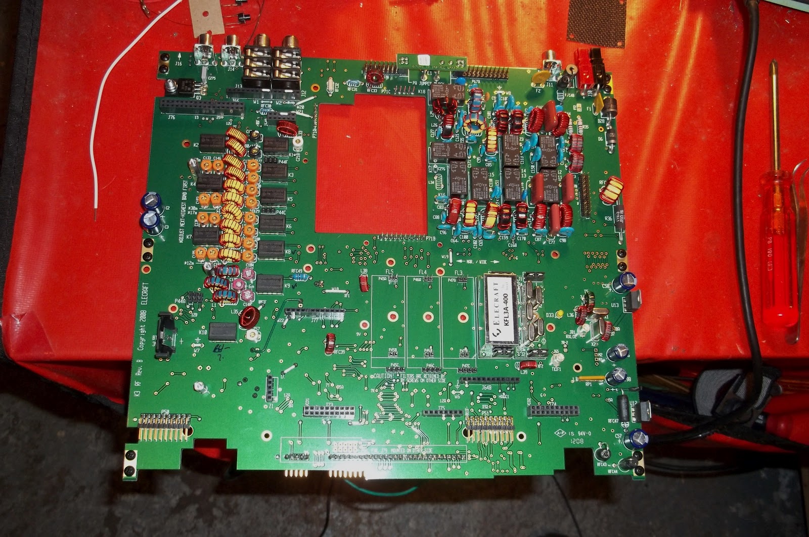
From there, things get added, like the filters. I have the standard 2.7Khz 5 pole filter and the 8 pole 400 Hz roofing filter.

These just go onto their edge connectors and then are secured by a screw and lock washer. For the various modes and bands, there’s space for up to five filters. I only have the two installed.
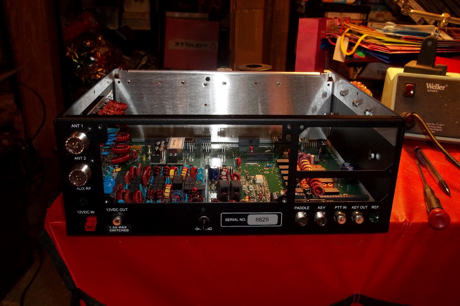
Next came the low power Power Amplifier board. This occupies the big hole you see in the upper center of the first photo.
As far as this K3 goes, that’s it. This will be a QRP version, so whatever I get out of this circuit is what I will be sending out to the world.
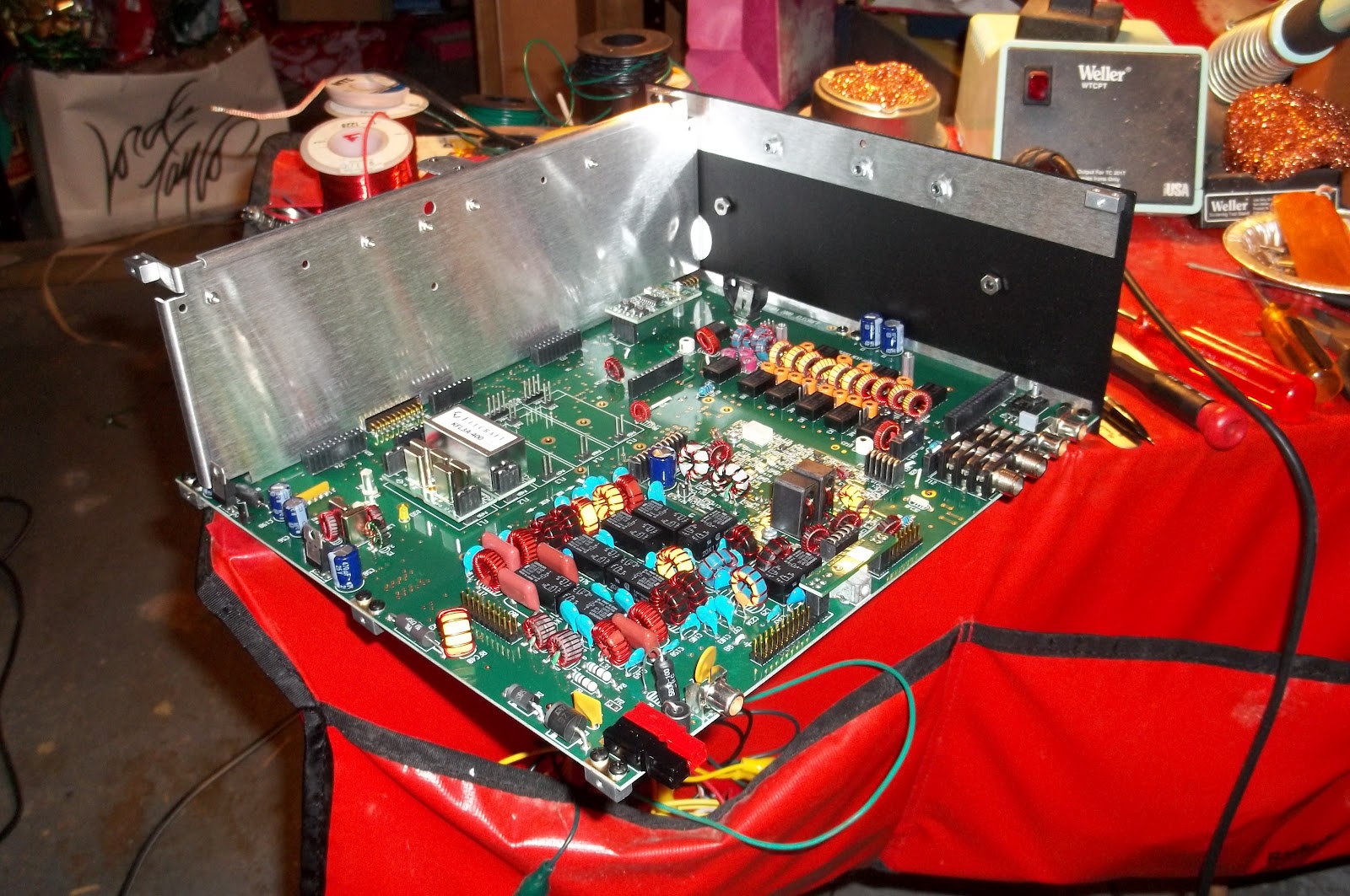
The next step is to start adding sides, and now this is beginning to look more like what you’d expect a radio to look like.
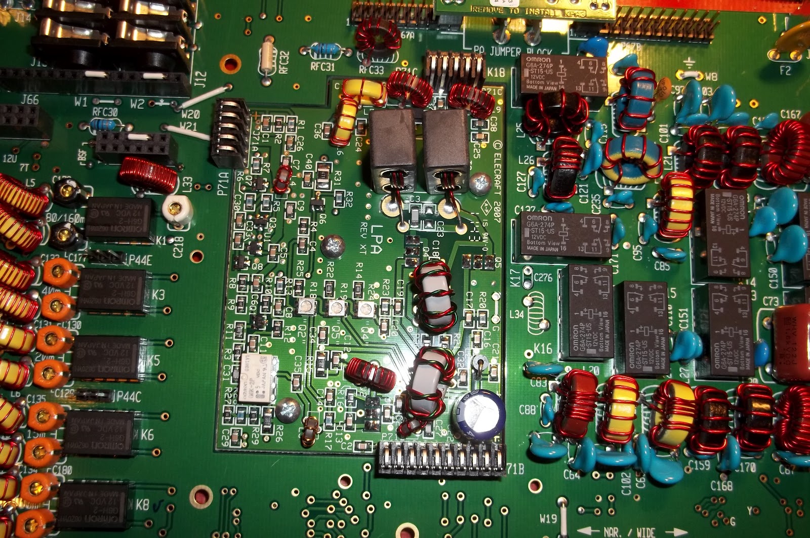
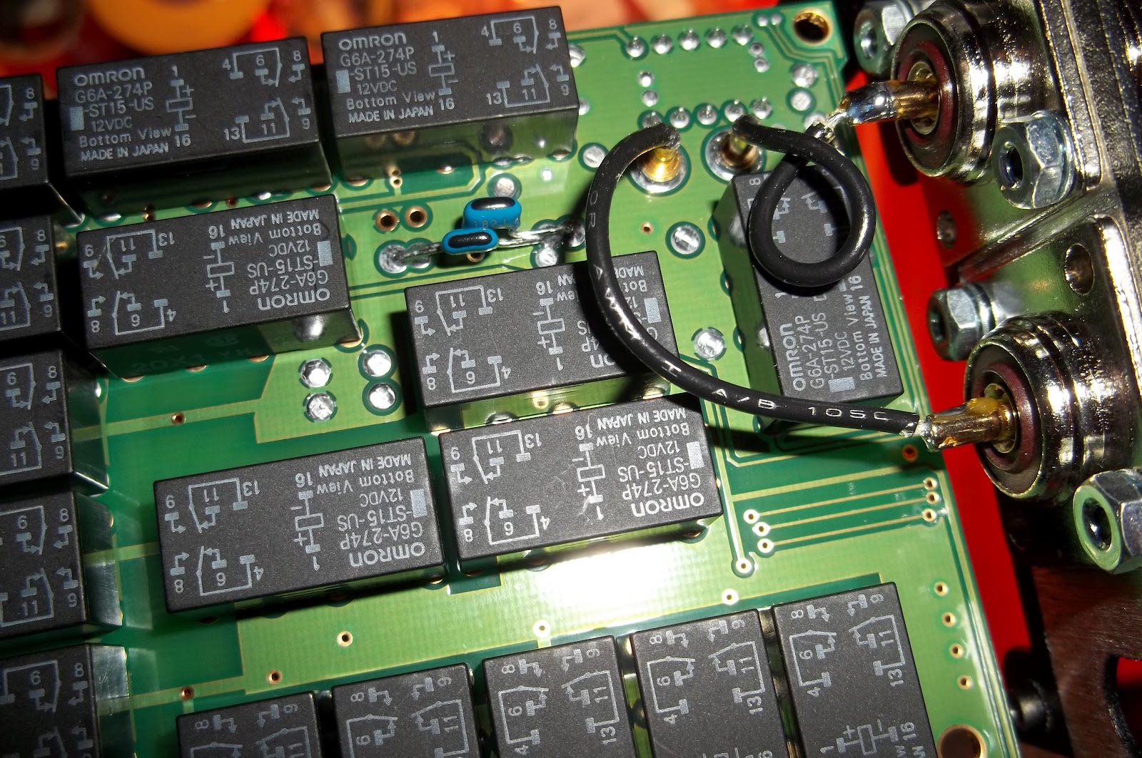
Installing the Auto Tuner came next. That in itself was easy. it just plugs into the main RF Circuit and is secured by hardware.
The hard part was getting the SO239 connectors plugged in. As you can see in the close up below, there are wires that get plugged into two brass sockets on the auto tuner board. The one wire slid into the socket on the left as smooth as butter. The one on the right was way more picky. I had to make sure the alignment of pin with socket was perfect. Then, and only then, did it go in – and even that took some effort.
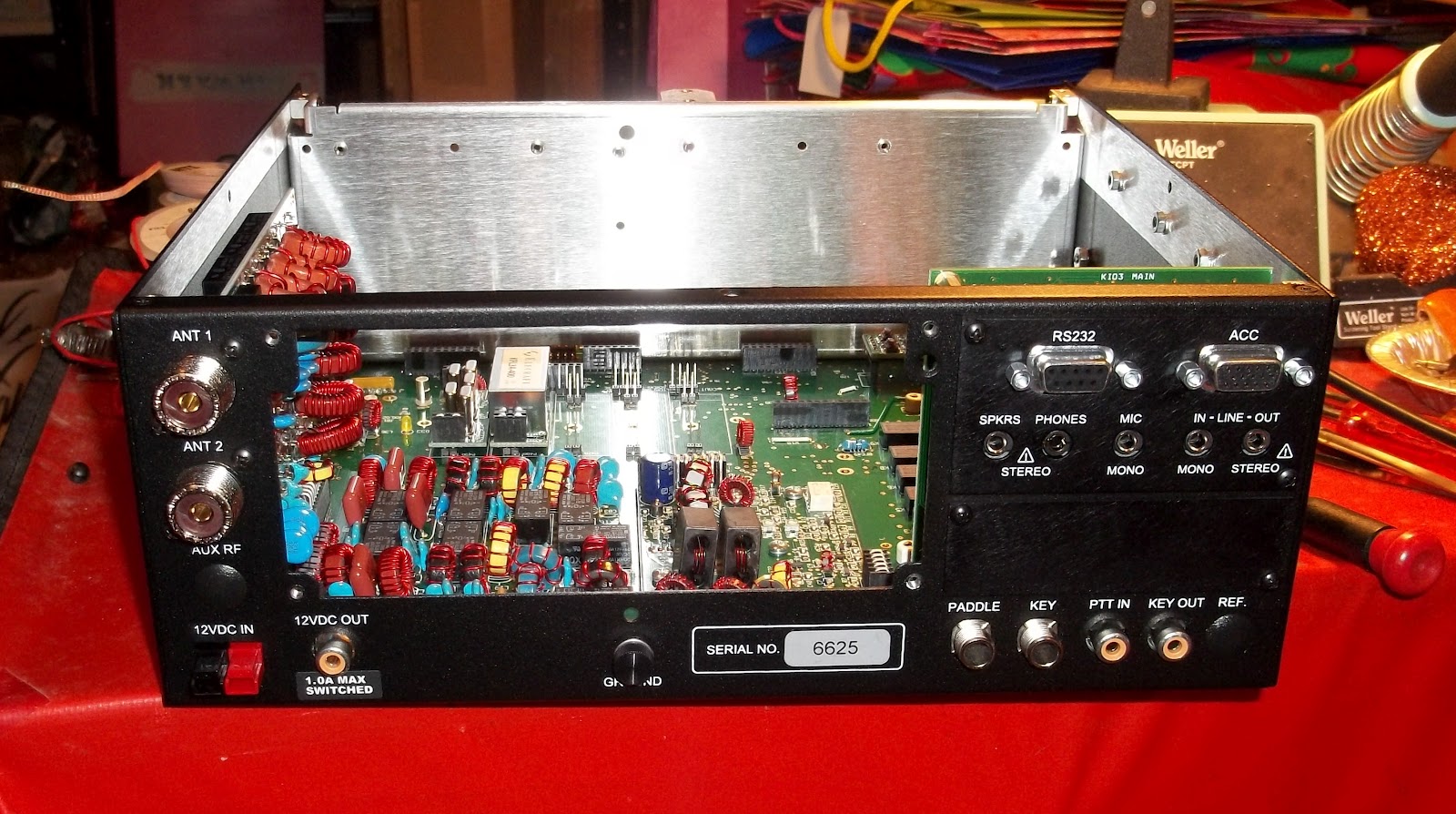
It is looking more and more like a real radio. And at this point, this is where I chose to stop for the night. I have put in about four hours worth of work so far. Tomorrow night, if I am not exhausted after work, I will begin work on the front panel.
72 de Larry W2LJ
QRP – When you care to send the very least!
 Ham Radio Deluxe |
 W5SWL Electronics |
 Ham Radio Prep |
 KB3IFH QSL Cards  Hip Ham Shirts  HamRadioAuctions HamRadioAuctions Reliance Antennas Reliance Antennas Enigma Shop Enigma Shop |  morseDX  Ni4L Antennas  R&L Electronics R&L Electronics antennas.us antennas.us QRV QRV |
- Matt W1MST, Managing Editor
