 |
 W3APL/B 903-MHz beacon
Late last Summer, it came to my attention that the 903-MHz W3APL beacon had gone off-line. The failure was intermittent and seemed to resolve itself after power was reset. Several efforts to troubleshoot it were undertaken by myself and others, including running it at high duty into a dummy load over a period of days. I was unable to get the problem to manifest itself on my bench.
A synthesized source (Analog Devices demo board) was offered by a friend of the Club, however it did not produce the desired output (or any output at all). It’s not clear whether this was the fault of the synthesizer or the user (me). The notional plan was to replace the beacon, which consists of a 75-MHz crystal oscillator followed by 12x of multiplication and a small RF power module, with the synthesizer and a new RF power module. The project languished, as they often do in my hands. But, two weeks ago I picked up the task again and made some real headway.
Really, the failure had to be one of a couple of things: 1. Intermittent connection exacerbated by thermal cycling. 2. Oscillator “unlock” due to component aging and thermal cycling. I reasoned that as long as we could eliminate #1, the multiplier chain and amplifier should be fine. The behavior seemed to point toward #2 or perhaps a combination of #1 and #2. I came across a forlorn Programmed Test Sources PTS-040 that I had rescued from another group’s surplus heap to put in my lab. I hadn’t used it in the two years that it was in my possession, so it seemed logical to provide it to the Club on a long-term loan. The problem was that it didn’t go up to 75-MHz. So, I cooked up a little multiplier chain. My “good” HP spectrum analyzer is on-loan to a paying program so I had to make do with the FFT function on the fastest Tektronix portable scope I had in the lab.
My initial effort at the multiplier chain was to build a 2N3904 amplifier that swung way into saturation producing a signal rich in harmonics. I went straight away for the 903-MHz signal but I couldn’t get a good enough lumped-element filter to eliminate the adjacent harmonics. So, I tried for the 75-MHz injection. This demanded a buffer amplifier so I lazily reached for the MMIC drawer in and retrieved one of the plentiful MAR-8s. Plenty of gain…and, as I would find out in a moment…conditionally stable! To exercise the eloquent euphemism of Ben, N3UM, the MMIC “burst into song” at about 63 MHz.
Back to the drawing board. I knew that I had something that would work, so I redesigned the deadbug layout on an SMD protoboard (the kind with all the pads in a grid). I replaced the discrete 2N3904 and MAR-8 MMIC amps with SGA-4586Z MMICs (which are a little too nice for this service, but I have a ton of them). Viola!
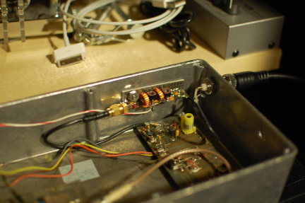
It’s the little board on the far wall of the diecast box with the SMA connector on the left and two toroids. 37-MHz RF comes in from the PTS-040 through the BNC jack in the wall. It’s multiplied up to 75 MHz on the new board and piped down to the remaining 12x multiplication and amplification stages before going to the little brick PA in the lower left (not visible).
So far, it sounds good. I was able to monitor it with my W1GHZ transverter strapped to the IC-290A in my car and using a WA5VJB cheap Yagi tossed in the back seat. I lost the signal about 5 miles away with that setup, which is really pretty decent all things considered at that frequency, etc, etc. Nominally, the frequency should be 903.054 MHz. I found it at about 903.048 MHz on the lash-up. Brian, ND3F (aka N3IQ/R) reported that he found it at 903.046 MHz with KA3EJJ’s setup. If you’re in the vicinity of FM19ne and are setup on 902/903, we’d appreciate a report. The big thing is the long-term stability. So, we’ll continue to monitor it.
Now…to get back to that 930 on my bench…
Ethan Miller, K8GU, is a regular contributor to AmateurRadio.com and writes from Maryland, USA. Contact him at [email protected].
A bit more DX
at lunch time today. I went to the park, threw the PAR ENDFEDZ into a tree and tuned up on 18.078 MHz. Janez, S51DX was calling CQ and he was loud so I put out my call and got into his log.
I probably won’t be able to get to the park until maybe Friday as the next two days are supposed to bring heavy rains to New Jersey. I’m not complaining, as it’s been a very dry spring (unlike the Midwest) and we can use the moisture.
The nice thing about the PAR ENDFEDZ 10/20/40 MKII, is that you can remove the factory supplied radiator and replace it with your own for any bands from 60 Meters through 10 Meters. This evening, I cut and tuned a radiator for the 17 Meter band. I used 18 gauge stereo speaker zip cord and pulled it apart. The other half I will use for a 15 Meter radiator. I soldered a ring lug to one end and then had to figure out an insulator for the other end.
The insulator that comes on the factory radiator looks like this:
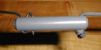
I don’t have any solid plastic like that so I used the barrel of a stick ball point pen. I cut it in half and drilled some holes and used the PAR insulator as a template. Since this is always used as a very temporary installation, it will be more than adequate.
I saw on QRPSPOTS that John N8ZYA worked A45XR in Oman using 3 Watts and his indoor random wire antenna. Great catch, John! About 90 minutes later, I was giving it a shot using 5 Watts. By the time I got on though, 17 Meters was changing, and even though the Omani station was still loud, he went QRT for the evening. Maybe next time. That’s the thing you learn with QRP – there’s usually always a next time, even if it takes 15 years for someone to take another DXpedition to that island!
72 de Larry W2LJ
QRP – When you care to send the very least!
Larry Makoski, W2LJ, is a regular contributor to AmateurRadio.com and writes from New Jersey, USA. Contact him at [email protected].
LHS Episode #105: Linux on the HamStack
 That’s right, we’ve got yet another interview in this show. Is anyone screaming “UNCLE!” yet? George from Sierra Radio Systems and Nick from Pignology are our guests tonight, talking about several of their ham radio related products. They have a product launch they’re doing at the Dayton Hamvention this year and wanted to let everyone know what they have in store so it’s out there before the chaos in Ohio. Don’t despair, howver. This is not a sales pitch. Instead, our fine feathered guests get down into the nitty gritty of their product, explaining what it does, how it does it, what hardware it uses and what software as well. You’ll be happy to know it’s all Free Software based and an incredible find for anyone looking for comprehensive remote station control. George and Nick also happen to be responsible for a significant chunk of the donation money LHS needed to be a part of Dayton this year so we are eternally grateful to them for that. The best part of all this: That’s only HALF of the show. This one’s so packed full of information it might just explode.
73 de The LHS Guys
Russ Woodman, K5TUX, co-hosts the Linux in the Ham Shack podcast which is available for download in both MP3 and OGG audio format. Contact him at [email protected].
The radio amateur who felt compelled to abandon his own call sign
If you mention that you are a radio amateur to any Norwegian who was old enough to watch TV in the mid 70’s then he is bound to respond with LA8PV. This was the callsign of the fictious figure Marve Fleksnes in the comedy the “Radiot”. To bad for the poor guy who actually was given that callsign some years later. I had contact with him on CW (= morse) in 2002 just after I got my license and I just couldn’t believe that anybody actually was using that particular callsign.
The first of three cuts can be viewed in the embedded Youtube video. Unfortunately I couldn’t find any clip that was subtitled in English, but the first minute or so is almost silent and is about the joy of getting a replacement DF1987B (sic) tube for his transmitter. The tube is supposedly plugged into the output tube socket of a Quad II audio amplifier and then he is ready to go on the air. Later one gets a glimpse of his AR88D receiver.
As the story goes, the Norwegian Post and Telcom Authorities, had marked off LA8PV as a callsign that shouldn’t be used. But due to a mistake they blacklisted LA8PW instead. I had contact with LA8PV almost every year up to and including 2007, but have never had it since. I understand why now, because QRZ.com says that the real LA8PV finally must have given up and gotten the new call sign, LA2WRA, on 4 Jan. 2008. I don’t envy him the fate of having been made LA8PV, and fully understand why he finally abandoned that callsign.
The source for much of this story is a Swedish discussion page on hamradio.se. Marve Fleksnes and LA8PV also aired on Swedish television and were very popular there as well.
Sverre Holm, LA3ZA, is a regular contributor to AmateurRadio.com and writes from Norway. Contact him at [email protected].
A not inverted Vee
And I’m not talking about antennas …….

Larry Makoski, W2LJ, is a regular contributor to AmateurRadio.com and writes from New Jersey, USA. Contact him at [email protected].
Max says it’s time to look at 50MHz again
The 50MHz and higher Es season seems to have taken a while to get started this year. For the last week or so, there have been some openings, but I’ve missed them.
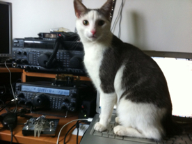
This weekend, I’ve at least managed a couple of contacts. The first, yesterday, with Max the cat’s help was a local one; M0RSE. A special call to promote morse code operated by members of FOC. Yesterday afternoon and evening there was some Es, but I didn’t get on until later. I was pleased to work CT1BXT for my first Es of the year.
You may remember that MW0IAN very kindly gave me a portable whip to work with the Palstar 50MHz handheld. It occurred to me this morning that it should work very well with the FT817, so I will try that on bike portable expeditions this summer. Thanks Ian!
Tim Kirby, G4VXE, is a regular contributor to AmateurRadio.com and writes from Oxfordshire, England. Contact him at [email protected].
SMD Project
When Steve, KD1JV, kitted another run of his MTR (Mountain Top Rig), I wanted one. It is however an SMD kit, but I thought why not take the plunge. However when the kit arrived with its cool looking case and I looked at the components I thought maybe I should have someone else build this kit. I didn't want to ruin such a cool radio with my learning mistakes. So I outsourced that one. However, I still wanted to learn SMD construction. Somehow I felt like a QRP wimp because I couldn't build SMD projects. So, what to do?
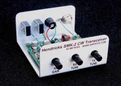
As I searched the QRP kit world, I found the perfect project. The SMK-2, a kit from Doug Hendricks, www.qrpkits.com, is a 300mw, 40m crystal controlled transceiver. It is specifically designed for SMD training. So I ordered the kit.

Mike Crownover, AD5A, is a regular contributor to AmateurRadio.com and writes from Texas, USA. Contact him at [email protected].
 Ham Radio Deluxe |
 W5SWL Electronics |
 Ham Radio Prep |
 KB3IFH QSL Cards  Hip Ham Shirts  HamRadioAuctions HamRadioAuctions Reliance Antennas Reliance Antennas Enigma Shop Enigma Shop |  morseDX  Ni4L Antennas  R&L Electronics R&L Electronics antennas.us antennas.us QRV QRV |
- Matt W1MST, Managing Editor
