Archive for the ‘radio’ Category
 Review: The World’s Most-Awesome Suitcase
 March 23rd, 2012 |
  Author: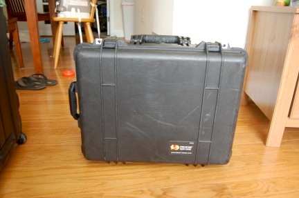
Air travel is hard on luggage. Just yesterday, I was sitting on the tarmac at Washington National (DCA) as we waited for our arrival gate to become available. The ground crew were loading baggage into the departing aircraft and did not elevate the loading elevator quite enough. Several suitcases and a Pack ‘n Play (the technical, brand-inspecific term for these things is a “playard”…who knew?!) toppled blissfully off the end of the elevator and landed in a pile beneath the aircraft. That’s just the stuff you see…
Until recently, I managed to travel carry-on only most of the time, something that preserved the life of my inexpensive soft suitcase far beyond expectation. However, the proliferation of checked bag fees has caused thrifty passengers to stuff as much stuff as possible into their carry-ons, making the overhead bins a nightmare. My employer is willing to pay for the first checked bag when I travel for work, which is 90% of cases or more, so thrift is slightly less motivating for me. I suspect that checked-bag fees have also increased the size of the average piece of luggage, making it perilous for my small soft-sided bag. So, like U.S. drivers of 10 years ago who preferred gas guzzling SUVs for their “safety,” I decided to fight back with a hard-sided suitcase.
After a trip to Europe in 2008 in which one of our soft-sided suitcases was essentially destroyed, Sarah was on board with this idea. I proposed a Pelican case at the time, but she thought it was ugly and “looks like a toolbox.” Since it’s a well-known fact that women drive household purchasing decisions, it should be no surprise that we ended up with a set of highly-rated, yet inexpensive hard sided suitcases. After one or two domestic trips, one of these developed a crack. The trip to Greenland in January of this year was impetus for me to take matters into my own hands: I bought a Pelican 1560 (empty with no foam) and the 1569 lid organizer.
The genius of the 1560 is that you can’t load it to more than 23 kg with “normal” contents. Although, Sarah—and airline, security, and customs employees the world over—would argue that very little that goes into my bags is indeed “normal.” It’s only a little more expensive than a department-store suitcase and definitely cheaper than most of the high-end brands. And, of course, it’s indestructible…and it floats. What’s not to like about that? There is one downside—it is almost always loaded to near 20 kg, so it’s heavy. But, until the airlines force us to pay by the kg, I have my suitcase for life.
Upon return from our latest trip yesterday, the two larger hard-sided suitcases had big cracks in them. “I think all of our suitcases should be Pelican cases,” Sarah remarked as we left the airport.
A Portable Vertical Antenna
With the loss of my preferred frequent flyer status, airlines tightening their checked luggage allowances, and the addition of another traveler to the family, I’ve been contemplating a new portable antenna that is easier to pack than my usual DK9SQ mast and dipoles. I don’t do high-priced reduced-size antennas if at all possible since portable installations usually have other efficiency-reducing problems. Multi-element antennas take up additional space and have feeding and installation complications that are unnecessary for the casual DX operator. So, that leaves us to choose between a vertical and a dipole.
A few words about efficiency: Dipoles have a distinct efficiency advantage over verticals in almost every practical installation for 40 meters and up, except when the vertical is physically placed in or over salt water. Radiation efficiency tends to be dominated by near-field conditions, pattern is dominated by stuff that’s farther away. This is why vertical dipoles work so well for long-haul DX when placed within a few wavelengths of salt water. They don’t need the near-field efficiency enhancement as much as base-fed verticals, but they still leverage salt water for developing their far-field radiation pattern, especially at low angles required for long-haul communication.
I’m a casual DX operator, not a DXpeditioner, so I never operate on 160 or 80 meters. That is, considering the discussion above, why I have been using dipoles with the DK9SQ. But, verticals have a distinct advantage over dipoles in the sense that they are self-supporting. I decided to build a vertical because: 1) my next DX trip would include time near a beach and 2) I wanted to be able to bring my own support as I had with the DK9SQ.
My remaining requirements were now simple:
- A vertical antenna that requires no additional supports. Guying is OK.
- The antenna must be full-size (quarter wavelength) on 40 meters and above.
- Experience has shown that multi-band operation is desirable, but instant band switching is not necessary.
- The longest piece must fit inside my suitcase (20 in / 50.8 cm maximum length).
- Field assembly and repair with only a Leatherman tool.
- Minimum cost, minimum weight, minimum volume, minimum installation time.
And this is what I came up with:
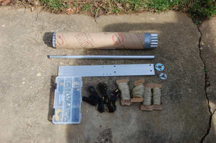
There are 21 aluminum sections, most with a “swaged” (actually, a poor-man’s swage to be described in a moment) end and a slit end. They are shown here bundled perfectly inside a section of cardboard shipping tube. An 18 x 2.5 x 0.125-inch aluminum plate serves as the base. I used DX Engineering resin support blocks to insulate vertical from the base. A point could be fashioned on the bottom of the base and a foot plate attached to push into soft soil, but that has not been done.
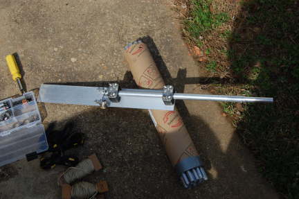
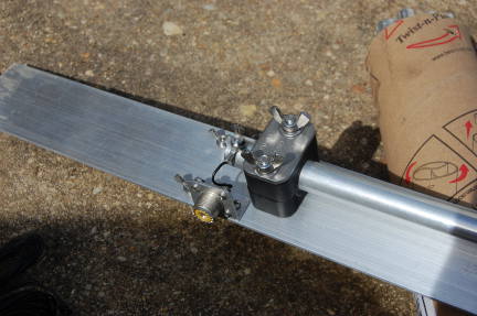
Most sections fit together using overlapping joiner pieces that I previously referred to as “poor-man’s swaging.” I’m not sure that it’s actually a savings over paying a local shop to swage the ends for you when time is considered in addition to material, but I cut telescoping pieces six inches long and fastened them three inches deep in one end of a 17-inch section of tubing with two offset and orthogonally-placed aluminum pop rivets for a total length of 20 inches. This geometry not only fits in my suitcase, but results in a very small amount of wasted material as well.
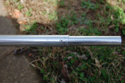
The other end of each piece is slit about 2 inches and they mate with an all-stainless steel hose clamp. The first 10 feet of the antenna are 0.75-inch 6063-T832 tubing followed by telescoping sizes down to 0.375-inch at the very top. The transition pieces are a full 20 inches long and are slit on both ends. The full-size antenna will stand in a light breeze, but guying is a good idea. Guy rings are fashioned out of flat washers drilled in three places.
Tune-up is easy…the more radials you use, the less critical their length. After about 8 or 10, you’re in the clear here. I never attached enough to prevent them from affecting the tuning. If you only plan to have a couple of radials, go ahead and cut them to 1/4 wavelength (even though ground proximity will detune them). Then, set the length of the antenna using the required number of 17-inch sections (the 234/f formula is surprisingly close) with the last section being a variable length for fine tuning.
I’ve intentionally left out most of the details of the antenna itself because I don’t expect anyone duplicate it exactly. But, here are a few notes for anyone considering building one themselves:
- There are lots of parts vendors out there. McMaster-Carr and DX Engineering will get you there in one order from each. There is a surprising amount of overlap in their inventories. Get the hose clamps from McMaster…even if you get stainless-stainless (stainless band, stainless screw), they are about 1/3 of the DXE price. On the other hand, the resin support blocks are cheaper from DXE.
- I carry a compact antenna analyzer (Autek Research VA-1) with me. Field tune-up is a snap and it runs on a single transistor battery. It’s about 1/4 the size and weight of an MFJ-259 and good enough for amateur work. Oh, and I bought mine used for a fraction of the MFJ.
- A tubing cutter is fine if you only have a half-dozen or so cuts. But, if you have a chop saw or need an excuse to buy a chop saw, it will make cutting the tubing far easier. My hands were raw for a few days after cutting the tubing by hand. I’m sure the antenna performs better on account of it, though.
- Find a friend with a metal-cutting bandsaw to slit the ends of your tubes. I went through a half pack (McMaster mega-size pack) of cut-off wheels for my rotary tool doing my slits.
- McMaster only sells the aluminum plate in 36-inch pieces. If you don’t have the aforementioned chop saw, an angle grinder with a cut-off disk does a surprisingly good job.
- I pack a combination-screwdriver that has hex drivers that fit the hose clamps and #6 nuts. Even though the antenna can be erected with only a Leatherman tool doesn’t mean it has to be.
- The small parts box shown in the top picture holds all of the parts for the antenna—it was 2 USD at Home Depot.
- The final and most critical component is a clip-lead that can be used to attach various nearby metal structures to your ground plane. I have used it to make a temporary radial out of excess tubing sections on 12 meters as well.
That’s it. The antenna goes up in a few minutes, especially if not used at full length. I used it successfully last week as OA5/K8GU, which will be detailed in a future post.
Happy Birthday WOTA
Happy Birthday WOTA. What do you get a portable operators scheme for its birthday? I simply have no idea.

For those who aren’t too sure what it is. WOTA is a bit like SOTA but for the Wainwright Fells in the Lake District. If you don’t know what SOTA is then one explanation is portable operations from summits (or fells if you live here in the lakes). Or as I like to describe it to non hams, working you way up a fell till you get to the top, looking at the view for a bit then getting out a radio (generally in the fog or rain, in the lake district) and saying ‘hello its me, can you hear me?’ ‘yes, it’s me, can you hear me?’ ‘yes, good stuff, who’s next’. I don’t think I’ve had too many positive looks giving that explanation but its better than trying to explain what that pole sticking out of your rucksack is in a howling gale.
Anyway,m back to the point. WOTA was devised by Julian, G4ILO and the first activations have been tabled as the 21st March 2009. So all I can say is happy birthday and my XYL wants a word with you because I’ve not managed to fix the downstairs toilet whilst I’m out operating from a fell top.
Scafell pike

Yesterday I made a secong attempt to activate Scafell Pike. Usually I got up to summits alone or with the dog bit this time was with a bunch who were training for the 3 peak challenge. Needless to say the summit was in cloud, it snowed then hailed then rained on me as I came down. Still this time I had a whole load more qso’s and a much more satisfying activation. Wast water (in the photo) is a beautiful lake that is surrounded by some impressive fells. Not as nice a Ennerdale but then again I am a bit biased.
W1GHZ 903-MHz TX Gain Compression
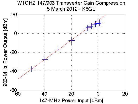
I managed to sneak into the lab again at lunch today for a few minutes and hooked up the now-packaged W1GHZ 903-MHz transverter to do a transmit gain compression test. This test is a quick and dirty way to find the linear operating region of the transverter in addition to the expected conversion gain on transmit. These two parameters determine the IF transmit level and what kind of power amplifier or driver stage will follow. It’s an easy test to run if you have the equipment. I locked the transverter in transmit by applying 8 volts to the TX MMICs and used a Rodhe and Schwarz SMR40 signal generator as the IF transmitter at 147.100 MHz. On the transverter TX output, I simply connected the HP 8565E spectrum analyzer that I’ve used in the past. Spectrum analyzers are not great power meters, but they give you a good enough idea of what’s going on. The 1-dB gain compression point (that is, the point where the actual device gain sags 1 dB from the linear gain) is at an input of -3 dBm or an output of just under 10 dBm. This compares favorably with the datasheet for the mixer and discussion with N3UM.
903-MHz cavity filter tune-up
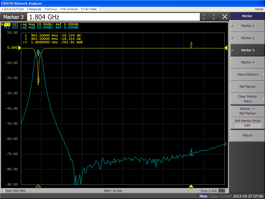
For reasons that will become clear in a future post or series of posts, we’ve been busy lately—don’t worry, it’s a good thing. I did manage to sneak away from my regular (usually desk-bound analysis) work into the lab and tune-up an eBay-special cavity filter for 903 MHz with our new network analyzer. It’s really amazing how you can dial these things in if you have the right tools. This one is a 3-cavity filter about 10x8x3 cm.
Passband insertion loss is about 1.2 dB. Harmonic rejection at 1.8 GHz is 70 dB down. I’ll take it.
I also have some eBay-special helical filters that were advertised to be for 432 MHz. So, I need to cobble up some carrier boards to try them out. Another day, another project.
Raspberry Pi announcement
For those who are following the progress of the ultra cheap pc proposed by Raspeberry Pi, I received this email this morning.
The Raspberry Pi Foundation will be making a big (and very positive) announcement that just might interest you at 0600h GMT on Wednesday 29 February 2012. Come to www.raspberrypi.org to find out what’s going on.
Eben Upton
Executive Director, Raspberry Pi Foundation
Perhaps they’ll be announcing pricing and delivery of what should be very useful lightweight PC’s (is that even the right way to describe them?)