Archive for the ‘ham radio’ Category
 What has been happening?
Anyone looking at my blog could be forgiven for thinking that I had dropped off the face of the earth for a while, has nothing been happening in my world?
Well, the answer is that a LOT has been happening and all at once. My daytime job has become busier and there have been several non-radio projects at home that needed to be completed. All this has kept me away from Amateur Radio blogging even though I have spent more time on the computer than usual.
In between projects I did manage to stumble across this video of Rear Admiral Grace Hopper explaining just how “long” a nano-second is and what it looks like. This has relevance to radio as we’re usually well aware of frequency and wavelength but don’t usually spend too long thinking about speed.
The ARRL Handbook
 My family sure was nice to me on my birthday this past Wednesday! One of the gifts I received was something I’ve wanted, but I couldn’t bring myself to cough up the cash for it: the 2012 edition of The ARRL Handbook for Radio Communications, graciously given to me by my daughter. Since the most recent copy on my shelves was several decades old, I was glad to get my hands on it.
I can see why this is a required textbook for the classes my friend Scott has been taking. He is a Signalman with BNSF Railway and periodically travels to Kansas City for training (no pun intended). The ARRL Handbook is a great resource for more than just ham radio operators. It is well-written and comprehensive — so comprehensive that I felt like an ignoramus as I paged through it on my birthday! I may have my Amateur Extra Class, but now I see more clearly than ever how little I really know.
But don’t let that scare you away from this book, Technicians. There’s still plenty in this book that you will find accessible, and anyhow we’re never going to learn if we don’t push ourselves.
One thing that isn’t covered in this book is the topic of operating procedures. But I can see why this topic has been relegated to a book of its own. The ARRL Handbook is quite a hefty tome as it is.
As with most of the ARRL library, you’ll find this book cheaper over at Amazon.


![]()
Say Goodbye to the BNC
 There was a discussion on Google+ the other day about how a particular handheld transceiver has an SMA connector, instead of the venerable BNC connector. I noted that many of the newer HTs are going with SMA, presumably because of the smaller size. In fact, I started thinking about it…I didn’t think you can buy an HT anymore with a BNC.
I took at look at some of the ham radio dealer websites to see if I was right. These radios all have SMA connectors: Alinco DJ-175T, DJ-C7T, DJ-G7T, DJ-G29T, DJ-V17T, DJ-V57T; ICOM IC-80AD, IC-92AD, IC-T70A, ID-31A: Kenwood TH-D72A, TH-F6A, TH-K20A; Yaesu FT-60R, FT-250R, FT-270R, VX-3R, VX-6R, VX-7R, VX-8R. The Wouxun radios are SMA but with a male connector on the radio (opposite gender compared to the other manufacturers…a topic for another day.)
But I did find three ICOM models that have BNC connectors: IC-V80, IC-V82, IC-U82.
The trend line is clear…the BNC is on the way out for amateur radio handheld transceivers.
Do I care?
Well, yes, I do.
I have a collection of extended length antennas that are much more efficient than the standard dummy load rubber duck. These are great for portable operation, mountaintopping, etc. I have not found very many of these antennas available with SMA connectors. Even if they were available, I am not sure I’d want to attach them to an SMA connector on an HT. For example, a 1/2-wave 2-Meter antenna is about 38 inches long — I am skeptical that an SMA provides enough mechanical strength to support it. Even with a BNC, I have always been very careful to not put too much strain on the connector.
We will have to see where this leads but it seems that the BNC will fade away for amateur use. Most mobile and base rigs use PL-259 and/or N connectors so HTs have been the main application for a BNC.
Goodbye, BNC, I am going to miss you.
73, Bob K0NR
Update on Feb 24: I’ve had several people suggest to me “just use a BNC-to-SMA adapter.” This certainly takes care of making a good electrical connection but mechanically they are generally weak.
Handiham World for 22 February 2012
Welcome to Handiham World.
Have you ever belonged to a book club or discussion group? Sometimes public libraries or local bookstores sponsor such activities. The idea is for everyone in the group to read a book and then come together to discuss it in a relaxed and cordial atmosphere.
I started thinking about this idea of having a discussion group while I was listening to one of our Handiham nets. As luck would have it, I was also browsing through the e-mail from my local radio club and one of the messages in my inbox had a list of potential radio club program topics. The idea of the book club discussion group and the message about radio club program topics started to mix and merge in my brain. Perhaps it would be a good idea to have a discussion topic on a regular basis during one of our nets, but make it related to a particular article about ham radio, much the same as a book club would discuss a particular novel. This would be different than the trivia net in that a roundtable discussion would be essential to make it work. The norm in many amateur radio nets is for the net control station to run the net in what I will call a “linear” format. In other words, the net control station opens the net with a preamble and then follows a pattern of calling for stations to check in with traffic or announcements or just to get on the station list for that day. Once checked into the net, a station operator need not feel obligated to check in a second or third time. In fact, if the net is run in this kind of linear format, the expectation is that permission will be requested from the net control station to “re-check” because it is assumed that once a station has checked in the net will move on to each new check-in in succession.
Of course this kind of linear format will not work in a discussion net. By its very nature, a discussion requires back-and-forth dialogue as ideas and concepts are presented and then commented on by the group. If you were sitting in a room at the library or bookstore with other book club members who have read the book of the month that has been assigned for discussion, how would you prefer that the chairs be arranged? My preference would be to put them in a circle rather than in a long line along one wall of the room. Having chairs in a circle promotes discussion, and what we want in a discussion group is the interchange of ideas. It is not an accident that this kind of ham radio net is called a “roundtable”. Sitting around the table encourages discussion.
So a linear format net is different in that very fundamental way from a roundtable discussion net. If you tune across the amateur radio bands and really get familiar with what is going on, you will soon learn that groups of friends meet at various places on the bands around the same time every day or evening. Most of these groups are really just informal roundtable sessions and did not have a specific net mission or formal structure. There are, however, some discussion nets that are more formal in that the discussion topic may be limited by the group to a particular interest area such as religion or aviation. What I would propose is something just a little bit different in that the discussion topic would change depending on which article is the assigned reading of the week. The net would discuss that particular article and then participants would be able to weigh in with their opinions and suggestions as well as comment on the opinions and suggestions of the other net participants.
One consideration with this kind of a targeted roundtable discussion group is that it tends to work best when there are not too many people trying to participate. If the group gets too large, this will hamper discussion because by the time everybody gets a chance to say their piece the allotted time for the net may be nearly over. As with any kind of a net, everything will run more smoothly when all of the participants know and follow the rules. Some of the basics are:
1. Always yield to the net control station.
2. Stick to the topic.
3. Be sure you have read the article before joining the net as a participant. If you have not read the article, don’t bother checking in but feel free to listen.
4. Try to be as brief and concise with your thoughts as possible so that everyone will have a chance to talk.
5. Play nice! Be respectful of everyone’s opinions.
6. Take notes during the discussion so that you can comment on what has been said while you are waiting for your turn.
7. Maintain good engineering standards for your station and computer system so that your audio is clean and easy to understand.
8. Be on time for the net. Remember, the discussion will begin right away so the expectation is that only the stations who are on time will participate in the discussion. Latecomers are welcome to listen to the discussion.
9. As the discussion comes to a close, be ready with ideas for the next week’s topic. At that point, the net control station can ask for other ideas and see if there is any consensus about the next article to be discussed. Sometimes this will not be possible to nail down, given the limited time available on the air. In that case, an e-mail message with a topic can be sent to the discussion group participants.
10. If the net decides that the topic will be carried over into the next week or that some other follow-up needs to be done, put that in your notes to make sure that you don’t forget to do whatever “homework” needs to be done before the next net session.
You can see that this is a whole different ballgame than the nets that we are used to. Most typical linear format nets require virtually no preparation and ask very little of participants. A discussion roundtable net requires a different level of commitment but at the same time can be a more rewarding experience because of the depth of your participation. Roundtable discussion nets are not for everyone, and no one need apologize if they are just not willing to commit the time and effort that this kind of net requires. I have often found myself tuning around the bands and listening to different roundtable conversations without actually participating. There is nothing wrong with doing a lot of listening – after all, you can learn a lot by listening. If a topic area seems beyond your understanding, listening is probably your best choice until you learn enough to join in. On the other hand, some people are adventuresome and jump off the highest diving board as soon as they get to the pool. “Learn by doing”, they will say, and they might just be right!
This morning I enjoyed listening on 3.930 MHz. “The Morning Group” is up here in Minnesota, but I’m sure you have similar groups located near you. Round table discussions need not be formalized with a net control station, nor do they have to have a scheduled topic. You may find this kind of informal net to be an interesting way to stay in touch with a small group of friends who share some of your interests. On the other hand, a directed net with a net control station can give a formal roundtable with a designated topic for the day just enough direction to make for a lively and fun conversation.
For Handiham World, I’m…
Patrick Tice, [email protected]
Handiham Manager
DIY Magnetic Loop Antenna – Part 2
Part 1 of the DIY Magnetic Loop Antenna covered mostly theory and materials so now its time to move on to designing the magnetic loop antenna (MLA).
If you have priced a commercially made MLA you’ll see prices start at $400 and keep going up, and up. If they cost so much you would think they must be difficult to build or use expensive parts, right? Well, it is certainly possible to spend more and get a higher quality MLA but a low cost MLA will still work very well.
For the purposes of this article we’ll assume that you want to build a loop to cover the 20-10M bands. I’ll run through the calculations required to build the MLA.
The required information for the MLA calculator is:
- Length of the loop
- The conductor diameter
- Frequency/s of operation
- Input power to the antenna
- We don’t really know the best length of the loop at the moment so I’ll pick 9 feet circumference as a starting point (It’ll still fit in the trunk of my car)
- Since we seem to be having better luck with sunspots now I’d like to try 10M so we’ll start with 29 Mhz as the highest frequency we’ll use.
- I have some copper pipe left over from an ice-maker install, it is 1/4 (0.25) inch in diameter.
- Input power to the loop will be 100W.
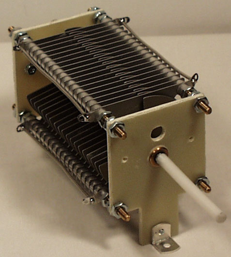
 A peak voltage of 5181V will require a minimum spacing of 1.7 mm (peak voltage / breakdown voltage per mm) between the closest conductors in the capacitor. That would rule out an old air spaced variable capacitor from a vacuum tube radio but you could still use a wide spaced variable capacitor from an antenna matching unit or transmitter. A vacuum variable capacitor would be great (watch the minimum capacitance) or a home-made capacitor would also be fine provided you checked the breakdown voltage of the insulating material.
 DIY Magnetic Loop Antenna – Part 1
Do you live in a neighborhood with a restrictive antenna policy and despair of having a useful HF antenna?
Can you solder or know someone who can?
A magnetic loop antenna may be the answer and they are not as difficult to build as you might think. Like getting on the air for the first time or taking your license exam there is a certain amount of uncertainty when you first approach magnetic loop antennas, there are a few new ideas to grasp. However, thanks to other hams like Steve AA5TB there are tried and tested designs, calculators & building methods that are known to work and that you can follow.
 At the heart of every radio and MLA (Magnetic Loop Antenna) is the resonant circuit. The combination of an inductor (a wire has inductance, but a coil of wire has more) and a capacitor (two conductors separated by an insulator) in a circuit will resonate or ‘ring’ at a certain frequency. Sound vibrations at a certain frequency can cause a piano string to vibrate in sympathy and a vibration of the correct radio frequency will cause a resonant circuit to electrically vibrate in sympathy.
Since there is no such thing as a free lunch, the sacrifice you make with a MLA is that it needs to be re-tuned whenever you change frequency on your transceiver. The frequency range over which it is resonant is very small, typically only a few hundred kilohertz at the most.
The materials you can get your hands on is going to decide the capabilities of your MLA. Ideally you’ll have a loop made from a conductor with very low resistance (usually copper) and a capacitor that can handle high voltages. A variable capacitor is required if you want to use your antenna on multiple frequencies but you can use or make a fixed capacitor if you operate on one frequency, for Eg PSK31.
A MLA calculator like the Excel spreadsheet from Steve AA5TB or this web page from 66pacific.com will help you to decide what size components you’ll need to make your antenna.
The four pieces of information required are:
- What frequency or frequencies do you wish to transmit on?
- How large do you want the loop to be (It should have a circumference less than 10% of the design frequency wavelength, both calculators help you figure this out)
- The diameter of your conductor (Three quarter inch (0.75 inch) copper pipe is a good start)
- How much power you want to use (The voltage across the capacitor is proportional to the input power to the MLA)
 A MLA of a certain circumference will be more or less efficient based on the frequency you transmit at. It is worth changing the loop size in the calculator to get the best efficiency possible in your favorite band.
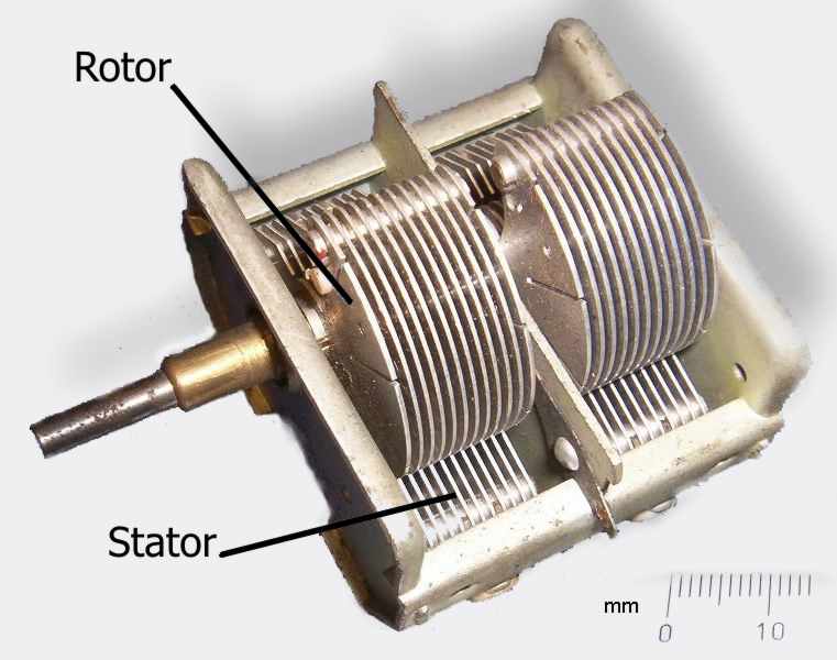
My Trusty Ol’ Heathkit HW-8
 Reminiscing about my early days in ham radio, one of the things that really stands out is a gift my parents gave me 32 years ago — a Heathkit HW-8, an 80/40/20/15 meter QRP CW transceiver! It was an utter surprise to me; I never had the slightest inkling that it was coming. I was 12 years old and had never built anything like that before. How wonderfully mysterious all those parts looked as I pulled them out and set them on the dinner table!
Looking back on it now, I realize how patient my mother was to let me take over that table in the dining room. As I recall, I worked nonstop to build the little rig and its power supply. Ten days later, on January 3, 1980, it was finally ready. My dad took a look at it and said it was ready for the “smoke test.” You can imagine how I held my breath as we plugged it in and turned it on. I was waiting for something on the circuit board to go up in a puff of smoke! Nothing exploded, so I was ready to take it into the shack and hook it up to an antenna and straight key. “Ready” is an understatement — I was so excited to get that rig on the air I was nearly bursting at the seams!
I picked up the phone and called Dr. Bernard “Bernie” Northrup, KAØDKN, a friend of mine across town, to see if he would get on the air and give me a signal report. Dr. Northrup (later NØCIE, now a silent key) was a professor at Central Baptist Theological Seminary of Minneapolis and a fellow member at Fourth Baptist Church, Minneapolis. Not long before, he had gotten his license after hearing me talk incessantly about ham radio at church (I’m afraid back then I was more interested in ham radio than spiritual things.). Anyhow, I called him (around suppertime, I see by my log!) and he graciously agreed to get on the air.
And sure enough, my HW-8 worked! After a half hour with Dr. Northrup on 15 meters I was ready for my first “real” QSO, as I thought of it. Tuning around the band, I heard ZL4KI. My heart started thumping as I prepared to call him. Could he really hear me even though I was sending with no more power than that of a small flashlight? My hand was shaking as I tapped out ZL4KI ZL4KI ZL4KI DE NØART NØART NØART KN and waited, flushed with excitement. I could hardly believe it when I heard my callsign as he came back to me! To think that the signal from this little radio, built with my own hands, was being heard 8,700 miles away in Invercargill, New Zealand! Amazing!
Other radios have come and gone, but that trusty ol’ HW-8 is still with me. As a boy I brought it with me to church camp and set it up in the lodge, tapping out CW while the other boys played games. Once on a trip to Louisville, KY I set it up on the second floor of my grandparents’ house — with a TV-twin-lead dipole my father had built — and worked a station in Poland. When I moved into my first apartment as a newlywed, I set it up with that same dipole in my (below-grade!) apartment. On a couple of memorable, crisp, autumn days, I brought it to a local park with a thermos of hot cocoa, sat down on a carpet of pine needles, and thrilled to the sound of soft static and CW.
And last summer, when I just couldn’t wait until I got my shack set up at my new QTH, I set it up on the picnic table in my backyard with an OCF dipole tossed into the trees. Even though that antenna was so low its feedpoint rested on the picnic table, I still worked both coasts on 20m with my trusty ol’ Heathkit HW-8! What a great little rig. Thanks, Mom and Dad, for giving me such a great gift!
(Click here to view the HW-8 Manual)


![]()


