Archive for the ‘antennas’ Category
 It’s SuperMoxon!
Today I replaced the home made 2m Moxon Rectangle with a Vine Antennas SuperMoxon. As you can see from the picture of it installed in my attic it is a Moxon Rectangle with two directors that are also folded into a rectangle.
 My attic, like my house, is very small. As is usual with modern British houses, the roof trusses are made of thin wood with cross-bracing for strength, so the attic area isn’t open to allow the free rotation of antennas. I have crammed rather a lot of antennas into this space to try to cover the maximum number of bands, so the VHF antennas have been forced into odd corners. Using a conventional small beam is not possible as there is insufficient space to allow rotation.
Vine Antennas claim that no other antenna gives so much gain in such a small turning circle, so it seemed like an ideal design for this situation. They claim that the directors add an extra 3dB of gain to the Moxon Rectangle design – about 9dBi which is more than a three element Yagi.
The antenna was quite expensive to buy. It is quite rugged and heavy but looks a bit home made. While the driven element and reflector made use of Jubilee clamps to tighten the main elements on to the smaller tubing used to form the corners, the directors used self tapping screws which had worked loose in transit (and probably would work loose in use due to wind vibration) and which stripped the inner hole when I tried to tighten them. You are left to your own devices to find a way to weather proof the feeder connection. Since my antenna is going to live a cosseted life away from the wind and rain I was not bothered by these issues.
The antenna presents a 50 ohm load but needs a balun to prevent feeder radiation. Vine Antennas offers a choke balun (apparently several turns of coaxial cable held in a loop using cable ties) for an extra £15. I decided to do without this, but I placed a clamp-on RFI ferrite over the cable close to the feed point which will hopefully achieve the same result.
The SWR is almost 1.0:1 at 144.0 MHz, as the plot from my AA-200 antenna analyzer shows, but it rises steeply to 1.4:1 at 144.4MHz and 2:1 at 144.8MHz. Clearly I had better not use this antenna to work satellites.
 It’s a bit early to say how performance compares with my old Moxon Rectangle. The beam width does seem sharper and the front to back ratio seems quite noticeable. I heard the GB3VHF beacon for the first time since it moved to its new location, but it is in and out of the noise on slow fading as it always used to be. I can clearly hear the Northern Ireland beacon GB3NGI, which curiously is the same strength on the SuperMoxon as it is on the ribbon cable Slim Jim (which is also due for replacement with a commercial antenna.)
This antenna is probably as good as I am going to get given the restricted space available. The SuperMoxon design is copyright Vine Antennas and commercial reproduction is prohibited, which should be borne in mind if you try to make your own version.
QRP TTF 2010 * Disappointed in Orlando!
On the road again… happy feet dance! K4UPG is loaded and ready for a good day by the lake operating the QRP To The Field event for 2010.

K4UPG ready to roll to QRP TTF site

Loaded with ALL the options!
Then came the wind knots in the antenna launching rig! I wanted to get a doublet up as high as possible. Took nearly 2 hours to get my antennas up in the air. LESSON LEARNED: It is really helpful to have another person along to help untangle all the knots that wire and string seem to make all by themselves. Getting the antenna up quickly is a key to portable ops. Grrrrr!

One of several tangled messes that delayed the antenna deployment
LESSON TWO: After a delayed start, I spent a lot of time moving my portable table to keep out of the direct sun! With temperatures in the upper 80′s it was HOT and direct sun causes my Sierra to drift a bit which makes qso’s more difficult. Need to get a sun shade setup and not waste time moving my position.
The band conditions were pretty poor and I did not hear as many stations as I had hoped. The ones I did work were tough going and seemed like others could not hear me responding to their CQ’s. I didn’t even hear a lot of Florida QSO party ops, but sounds like others that were farther away did. In 5 hrs I managed three whole qso’s with TTF stations. I did hear one Polar Bear– Martin operating as VA3OVQ but he could not hear me when I replied to his CQ.

Warning sign about 30 feet from my operating site!
It was fun to be outdoors and playing radio! I did not get eaten by our neighborhood gator either! Maybe next time out will be better contact-wise.
The Amazing KGD
 On the WSPRnet website DM1RG posted some results obtained using a 30m dipole 1.3m long, the “Kurz Geratener Dipol“. His 5W signal made it all the way from Germany to Australia. He finds the KGD to receive only 3 to 5dB worse than his “big vertical antenna.”
I tried translating the article about the KGD using Google but it didn’t make enough sense for me to understand how to make one. Perhaps someone will figure it out and publish a better explanation. It looks to me to be an interesting idea for anyone with antenna restrictions or simply wanting a second antenna so they can run WSPR or monitor a band while they operate somewhere else.
EME with a handheld
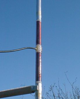
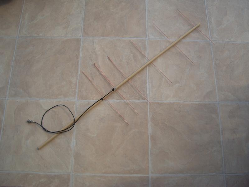
This morning I made a 6 element Yagi for 70cm using some 25A copper mains wire with the insulation stripped off and a length of wooden dowel. I copied the design from CT2GQV’s blog. The object is to see if I can hear radio signals bounced off the moon.
 If you didn’t know, a bunch of guys that include Joe Taylor K1JT of WSPR fame have got permission to use the 1000-foot dish of the Arecibo Radio Telescope (shown above) for a couple of hours each day over this weekend to make radio contacts via EME. Using full power their signals should be strong enough to be heard using a hand held yagi and it should be possible to work them using just 100W with the same antenna.
I only have the FT-817 with 5W so it isn’t possible to try to work them, but I thought I would try to hear them, which is why I made the antenna. I think you’ll agree that their antenna is more impressive than mine! There are, of course, no 70cm signals to test it on, but there are plenty of noises and the yagi seems quite directional. The SWR is about 1.7:1 at 432MHz and falls gently as you go lower in frequency, but I’m not sure how to adjust it so I’ll leave it as it is for the moment.
 The first session was yesterday. Unfortunately their PA blew up so they were only able to run 25W of power. Some contacts were made, but obviously not with people using low power and hand held antennas. Hopefully they will have got a PA working in time for the remaining two sessions, otherwise I am not going to hear a thing.
This evening they should be on between 1740 and 2020 UTC – that’s 1840 to 2120 BST. They will be transmitting on 432.045MHz using SSB or CW. Their call is KP4AO. The moon is only showing quite a thin crescent at the moment so it may not be easy to spot during daylight, even assuming the sky is clear as it is here. If you are in the UK the moon will be at an elevation of about 45 degrees to the south-west at the start of the session, declining to about 25 degrees due west by the end of it. If your QTH is elsewhere you can use this web site to locate it.
Tomorrow’s session is scheduled for 1840 to 2125 UTC – 1940 to 2225 BST. The moon will be in the same position relative to the start of the session.
Fingers crossed that they get the PA going so we can have a chance to hear something. If not, the antenna won’t be wasted as I’ve been meaning to have a try at satellite communications.
Shootout on Tallentire Hill
 It has been a glorious day today. After lunch I set off for Tallentire Hill armed with the TH-205E and three antennas: a 2m telescopic quarter wave, a 45″ 2m 5/8 wave Black Whip telescopic from eBay seller jeepbangkok and the SOTA Beams MFD.
I set up the MFD in the vertical position strapped to a fence post and put out some calls. Despite my high elevation the 2m band was quiet and I only managed to raise “the usual suspects”. Richard MM1BHO/M heard me calling through the GB3DG repeater and we had a short QSO. Then Keith G0EMM heard me call on 145.500 MHz and was willing to spend a bit of time doing some antenna tests.
Prior to this I had heard a contact on the GB3CS repeater and had quickly swapped all three antennas to see what the difference was on receive. There was no noticeable difference between the MFD and the Black Whip but both were significantly superior to the 1/4 wave telescopic (which is itself an improvement over the short whips and “duckies” normally used with 2m handhelds.) However the signal was steady on the MFD whereas it varied depending on the position in which I was holding the TH-205E with the BNC mounted antenna. When using the MFD I was sitting on the ground so it was above my head and my body wasn’t interfering with reception. When using rig-mounted antennas it is best to stand up as an extra couple of feet above ground make a noticeable improvement. But it is also worth turning around and moving a short distance as the direction you are facing can make a big difference to signal strength.
Keith confirmed that there was no difference in my signal between the MFD and the 5/8 telescopic. I was 59 on both of them, whereas I was only 4 by 3 on the quarter wave. Keith also gave me my second unsolicited complimentary report on the TH-205E audio, saying it was “just like my voice.” I was using one of the cheap Kenwood speaker mikes which I bought on eBay originally for the TH-F7E.
We were then joined by Colin 2E0XSD who again said that I was the same strength, 59+ on both the MFD and the 5/8 wave. I was only 4 by 7 on the quarter wave.
After I finished the contact with Keith and Colin I tried some more calls. I was able to access the GB3CS repeater using the MFD and the 5/8 – when in the right position – but not with the quarter wave. Some repeaters I could hear but not access even with 3W, which is what the TH-205E appears to put out on “high power” with the 7.2V battery pack, but perhaps they don’t respond to 1750Hz tone-bursts.
 When I bought the Black Whip a few weeks ago I put it on the antenna analyzer and got this SWR curve. I seem to remember that I had to collapse the topmost section to get the SWR null spot on 145.000 MHz but I don’t suppose it makes any difference in practise.
I think the Black Whip 5/8 telescopic is a superb antenna for 2m FM use and well worth the few pounds it costs, as long as you have a radio that can handle it. The base is sprung to absorb any shocks but even with the HT Saver SMA to BNC adapter I was a little uncomfortable using it on the tiny TH-F7E. The big old TH-205E has no such problems with a large antenna, although its lower power output with the battery pack I have is a slight disadvantage.
Is it worth carrying the MFD instead of the 5/8, which telescopes down to the same length as a quarter wave telescopic antenna? Well, if you are using a modern hand-held radio then the MFD’s coaxial connection will avoid putting undue strain on the SMA connector. You can secure the MFD to a fence post or stuff the support mast in your rucksack allowing you to operate sitting down and even let go of the radio when receiving. The MFD is also convertible to a horizontal dipole for SSB use. So it still has several benefits. But I expect I will be taking the Black Whip on most of my hilltop outings.
New British end-fed antenna
Cross Country Wireless will be announcing a new product at the Blackpool radio rally this Sunday. It’s an end-fed antenna consisting of matching unit, wire and an insulator, and comes in three versions for 40m, 30m and 20m.
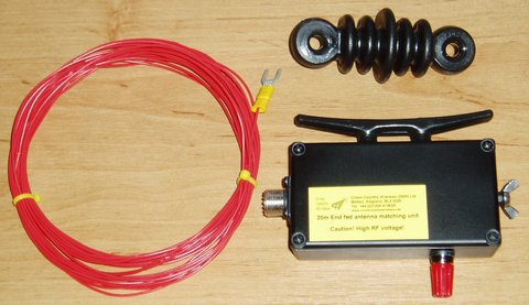 Many users speak highly of the performance of the Par EndFedZ antennas from the USA. It will be convenient to be able to buy such antennas from Europe without the hassle and expense of import charges, and it’s good to see new amateur radio products being made here in the UK.
The NA-034 operation that almost wasn’t: Epilogue
Well, I was wrong. Or was I?
When I got home after my NA-034 operation, I wanted to try to understand what happened. I was sure that I’d operated solely off a car battery in the past and as long as I was connected directly to the battery I hadn’t had any problems. Based on some testing that I did, I discovered that I may have been mistaken. The short version is that I discovered that by using the battery in my car without the engine running, I was able to reproduce the “strange noise in headset” that I recently wrote about, and that by running the car engine, that problem went away. There’s a bit more to it though. Read on if you’re interested.
I needed to have some way to measure the voltage from the battery and the amount of current  that it was drawing while the radio was transmitting. While I could do this with a couple of meters when I was home, based on some recommendations that I got from W3FF, K8EAB, and NE1RD, I picked up a Super Whattmeter from Astroflight for around $50 plus shipping. These devices are used by folks who fly electric model airplanes because you really don’t want your battery to die when it’s up in the air. As it turns out, they are well-suited for monitoring your power when operating portable. Of course, they work fine too in the home shack, though my power supply has meters so it’s not needed. The picture here shows it hooked up that way for testing, and you can see that the Astron supply is supplying 13.8v.
 As a side note, I started using quick-disconnect connectors made by Workman Electronic quite a number of years ago, before Anderson Powerpoles became popular. I was looking for some kind of quick disconnect power connector and found patch cables similar to the ones in the picture at a hamfest. I typically cut them in half and crimp them onto whatever I need to, be it battery clamps, the power cord for a radio, and so on. The good part is that I’ve been able to find them surplus at hamfests (though I’ve seen from a number of places online that they are now discontinued) but the bad news is that they don’t match what most other folks use. I keep meaning to make myself a set of adapters to connect to Powerpoles.
I crimped a set of the quick disconnects onto the Whattmeter and did a test with the power supply and radio in the shack to ensure that the meter was working and found that it worked perfectly. The shack power supply was putting out just over 13.8 volts with the Icom 756 Pro II drawing around 3 amps while receiving. (Interestingly, this is about 0.6A below what the ARRL reported in their testing, but I’ve had some repair work done on the radio and it’s possible that some of the newer components draw less than the originals.) The next step was to reproduce what I’d set up while in Florida.
As luck would have it, the weather was beautiful this weekend, and as we had no plans on Sunday, I took the 706, the Buddistick, the Whattmeter, the antenna analyzer, and a length of coax outside. I set up the Buddistick on the front lawn (I just had it on the mini-tripod sitting on the lawn, though I did put the radial over a couple of plastic lawn chairs to keep it off the ground) which while not optimal for DX, took me all of 5 minutes to set up with a good match to the radio, as verified by the antenna analyzer. I connected the radio to the antenna then connected the power cables to the car battery, with the Whattmeter in-line. My thoughts were to do a few tests with the engine off, fully expecting that I wouldn’t have any issues, then turn the engine on to see what kind of difference it made. I found an empty frequency on 20m and started testing. As soon as I transmitted, without looking at the meter, I knew that, to my surprise, I’d reproduced the problem: That nasty noise in the headphones was back.
What I figured I’d do was to collect data using various levels of transmit power to see the effect on the voltage and current draw. The meter itself also shows power in watts, though of course that’s trivial to calculate if you already have current and voltage. (From Ohm’s law, P=I×E). I quickly discovered that the car battery wasn’t able to supply sufficient voltage unless I was transmitting with about 10 watts or less. The specification for the 706 MkIIG is that it requires 13.8vdc ± 15% meaning the minimum allowable voltage is 11.73vdc. With the car engine turned off, I measured 11.68v with the radio drawing 5.79A when transmitting using 10w. At 40w (the next step I measured; when I was in Florida I was able to “get away” with 40w when testing with KH6ITY), I measured 11.52v while drawing 8.23A. At 60w transmit power and up, the voltage dropped to about 11.4v but the radio was simply unable to draw the current needed.
 With the car running, it was a completely different situation. Even at full transmit power (100w), the voltage supplied to the radio was 13.24volts at 14.77A. (I’m not sure why my current draw measurement at that power was different from the specifications for the radio, which were also pretty close to what the ARRL measured). I took the results and plotted it out in transmit power vs. watts consumed for both the case with the engine on and the engine off, and it’s pretty clear that with the engine off, the battery simply isn’t able to supply the required power. (You may need to click on that chart to have it display in a readable size. If you’re reading this via email and that doesn’t work for you, go to the web version of this post at k2dbk.blogspot.com and it should work from there.)
You can see from the chart that not only couldn’t the battery supply sufficient power for the transmit needs, it was only able to supply less as the radio tried to use more, presumably because the battery simply couldn’t “keep up”. So all my empirical testing seemed to prove that with the setup that I was using, I simply couldn’t operation at full power using just a car battery with the engine running.
However, similar to bees who simply don’t know that they can’t fly, so they do, apparently my radio didn’t know that it didn’t have enough power to operate, at least during my 2004 and 2006 operations from NA-034, so it worked just fine. During those operations I know that I did not have the car running, yet I had no issues with power. The key for me know will be to find out what has changed. I am using the same power cables and the same radio (the antenna was different, but that shouldn’t matter), yet something has changed. The next thing I am going to do is to see if perhaps there is a problem with the power cables that may have occurred over the years.
Although I attempted to measure the resistance in the power cables and came up with a measured 0.1 Ohms, my meter is probably fairly inaccurate at such low resistance, so I did a calculation instead assuming that I’ve got all 12 AWG wire in place. (Part of it is actually 10AWG, but I’m using 12 to account for any losses due to connectors and splices.) Using a 12v supply with a load of 15A (matching what I saw when the engine was running) and a length of 20 feet, the voltage drop calculator that I used shows an estimated voltage drop of around 8%. Allowing a bit of wiggle room for the length, it appears that the voltage drop would be somewhere between around 6% and 10% which corresponds to a voltage at the load (radio) of between 11.3v and 10.8v. Even the highest end of that range is too low for the radio to operate properly. Dropping the transmit power to 40w results in the voltage to the radio of about 11.5v which is a bit below spec but probably would allow operation, with some minor distortion. That seems to match what I had experienced.
The other factor that I haven’t played around with much is temperature, and I’ll leave that as an exercise for the reader. At this point, I think the best thing to do is to shorten the power cable as much as I reasonably can, replacing the section that is currently 12AWG wire with 10AWG wire. I suspect that will help ensure sufficient current flow while minimizing voltage drop.
I would be very interested in any feedback from anyone who can shed a bit more light on these issues, as I know that there are other factors that may come into play, such as the battery chemistry and perhaps other parts of the car’s electrical system.


