Archive for the ‘antennas’ Category
 A New 630m Loading Coil & Variometer
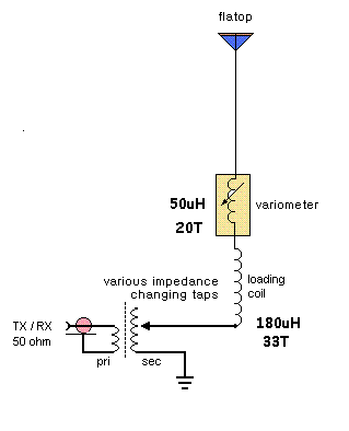
I've decided, for the time being, to keep my 2200m (136kHz) antenna tuning system separate from the 630m system. This means that I'll need to build a new loading coil, variometer and impedance matching transformer. I'm not really sure why I should maintain the 2200m capability since there is not really much activity here. The only two excuses that I have at present are the fact that it took a heck of a lot of work to get to this point (but it was mostly "fun work") and that the U.S. may be getting the band soon. I'm also not convinced that even if the U.S. does get the band that it would translate into much new activity....so, for the time being, I will keep the system intact.
I've used an online coil calculator to design the coils needed for loading and for the variometer....it will be interesting to see how close the finished values compare with the calculated values. I hope they're not too far off! Here is what the plan calls for:

The main loading coil will be built on a low-loss 6" styrene pipe coupler using #16 solid copper transformer wire, spaced at 3mm. The coil will be elevated above the main form by strips of styrene rod that I have filed small notches into, every 3mm. The rod height will be staggered around the form, gradually stepping down one full turn every 360 degrees. Inside the main coil, the smaller variometer coil will be wound with poly-covered #18 stranded wire on a short length 3 1/2" PVC pipe.
Hopefully I'll get something that tunes from 130-230uH, approximately....if so, I'll not only be happy, but really surprised!
Antennas
At the moment, I can cover 6m, 2m and 70cm vertical with the V2000, 2m omni-horizontal with the 2m halo, 2m and 70cms SSB/CW/digital with the small, hand rotated beam (3el/5ele) and 10m, 20m and 40m with the end-fed PAR wire antenna strung up to a tree. I can get on 630m by loading up the coax cables to various antennas or using the earth electrodes in the ground. I can get on other bands too by tuning various coax feeders.
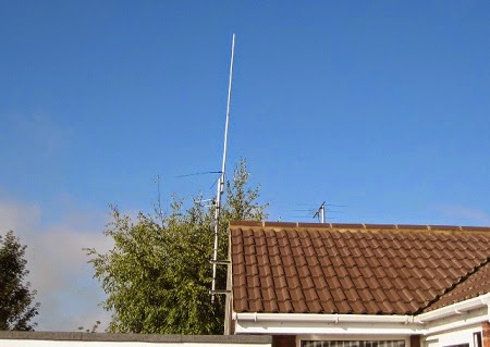 | |
| V2000, 2m halo, and 2m/70cm beam (hand-rotated). PAR end-fed is not visible but goes to a tree. |
I will probably take down the V2000 and 2m halo later and replace them with a 10m halo (Homebase-10) for the months until next spring. I think the 10m halo will be a more effective antenna for 10m than the PAR. It will certainly be higher. Main problem at present is my mobility: climbing ladders is not a good idea in my present state, so antenna work is all but impossible.
Despite the low power (5W or less) and lowish elevation, I am able to work out to around 200km on 2m and 70cm SSB in contests.
UPDATE WEDS: 449km best DX (Scotland) on 2m in the UKAC last evening with 5W and 3el.
630m Trans-Pacific WSPR
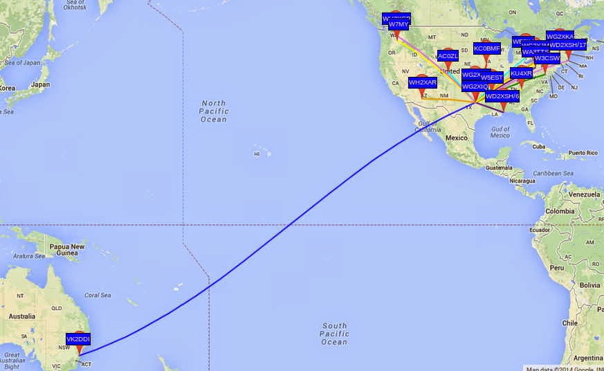 |
| Courtesy: https://www.google.com/maps/ |
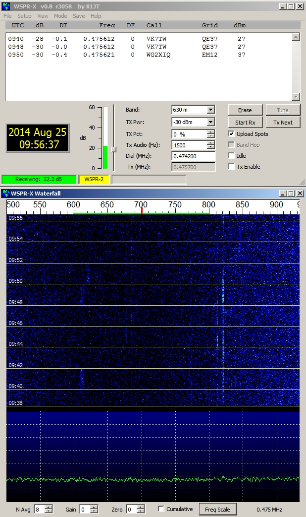
This is particularly noteworthy in view of the relatively low power used for John's beacon....around 200W. With the typical backyard antennas being used at these frequencies, efficiencies are very low and John's actual ERP is less than 5W. The transpacific reception of John's signal by VK2DDI confirms what most LF'ers already know....that small suburban lot amateur installations can have positive results on 630m without the need for huge antenna systems.
The WG2XIQ beacon was operating in the WSPR mode, which has become very popular amongst 630m experimenters as well as those just interested in listening-in. WSPR is not a QSO mode but strictly a one-way 'beacon' mode. Although two stations may each spot each other, it is not considered to be a valid two-way QSO. A check of evening WSPR activity will often reveal dozens of stations actively spotting what they are hearing.
Like most LF stations, John's is mostly homebrew.
 |
| WG2XIQ/KB5NJD |
I'll let him describe the details:
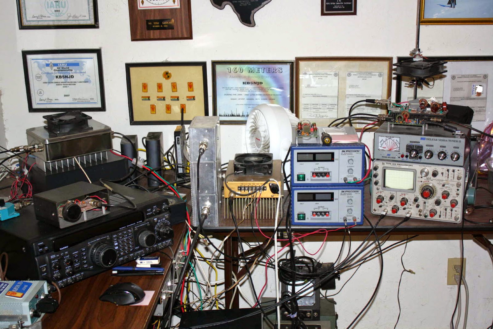
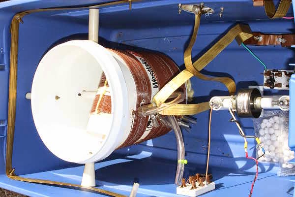
"I have a few ways of making RF in the shack. I can do CW with a very nice waveform using the GW3UEP VFO/Driver coupled with a GW3UEP 100w amp with waveform shaping. The other way is via the MF Solutions transmit downconverter, developed by John Molnar, WA3ETD/WG2XKA. I have two of those boards, one is a backup. I use a GPSDO for the LO and use that signal to drive two parallel GW3UEP amps with max power at 125 watts each. The W1VD Ø degree hybrid combiner brings them together in phase for close to somewhere between 200 and 250 watts TPO depending on how hard I drive and how close I match the TX levels entering the combiner. I filter the output with the W1VD KW LPF that was built by Dave Robinson G4FRE (ex WW2R). I power the amps with a pair of BK Precision 30V 6Amp variable power supplies (variable current limit threshold also). Scope match is used to resonate and match the the impedance. IF Rig on 630m is typically a Yaesu FT920. These days RX antennas are the VE7SL multiturn loop or the TX vertical, both of which have their own merits depending on the conditions at the time."
 |
| John's 630m Vertical |
"Antenna is an 80 foot asymmetric T-top marconi with 100 foot and 200 foot legs....radial system is almost 3 miles of radials connected via various busses. 26 ground rods around the property. I monitor current in the shack and sample via a Bauer current transformer from an AM BC ATU."
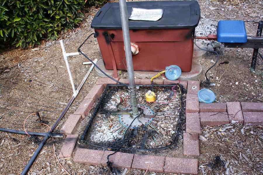 |
| 630m Radial System |
 |
| 630m Antenna Loading Coil & Variometer |
John's system does indeed work well...just last year at this time, his 630m signals were copied by KL7L near Anchorage, Alaska.
Of course, equal credit must be given to VK2DDI for having a system good enough to hear John's signal all the way down on Berry Mountain, New South Wales, Australia! It is there that David has set up a fine LF station, 500m above and overlooking the Tasman Sea...an ideal location for weak-signal LF work.
 | ||||
| VK2DDI - Berry Mountain, NSW |
 | ||
| WG2XIQ Signal As Heard in VK |
David also runs the Berry Mountain Grabber, providing other VK and ZL experimenters a handy way of checking their system progress or propagation conditions.
If you have been doing any WSPR work on HF, you might be surprised at what you can hear down on 630m, even without a dedicated antenna for that band. Surprisingly good results can often be had with a non-resonant antenna as the signal to noise ratio can often be better even though signals may sound weaker. Give it a try and spot what you hear!
If you are interested in learning how to receive WSPR, here is a nice tutorial by ZS6SGM.
Should you be interested in knowing more about obtaining a Part 5 licence to transmit on 630m, John will happily guide you through the process. He can be contacted via email or you can find him hanging-out most nights on the ON4KST kHz (2000-630m) chat page.
To keep on top of what is happening or who is on-the-air, most LF'ers rely on three sources:
- the RSGB LF Group reflector
- the Lowfer list
- the LWCA Message Board
Bit About Antenna Tuners
Something has bugged me for a long time — the way some radio manufacturers market and sell their transceivers with built-in automatic antenna tuners. These are almost always intended to be used with antennas that are sold by the manufacturer (for instance, a specific mobile antenna) but this is seldom clear in large print in the adverts.
An unsuspecting ham may think the auto-tuner in his shiny new HF rig is going to work with the new dipole he hung up between the trees, only to discover it’s a hot mess.
Due to their size, most internal tuners (there are some exceptions) can manage only a slight mismatch in impedance and cannot begin to cover a wide range like that presented by ladder line and wire antennas. The explanation for this is fairly straight forward.The antenna and feed line present a load to the output of your transceiver. Most modern equipment has been designed to work with a load impedance of 50 ohms. Get close enough to that, and the transmitter is a happy camper. But if the load impedance is something other than 50 ohms, you have a mismatch. A mismatch causes a certain amount of the power that you’re trying to get out to be reflected back down the line — where it encounters forward power from the transmitter resulting in standing waves on the feed line.
You’ve doubtless heard of this in discussions about SWR or standing wave ratio.
A high SWR can cause considerable RF voltages in the feed line — and at the output of your shiny new radio. This isn’t healthy for modern transceivers (tubes are a little more forgiving) so manufacturers have taken to protecting equipment from this condition. When it’s sensed, your rig may fold back its output power, or shutdown altogether in order to prevent damage.
And this is why hams use antenna tuners. Most of us would like to be able to operate over many frequencies with a single antenna. Since the impedance of that single antenna will change depending on the frequency of the transmission, a tuner becomes a useful tool.
Basically, a tuner is a combination of inductors and capacitors that act to balance the load reactance at the transceiver end of the feed line. With the reactance effectively canceled, the load impedance at the transceiver is 50 ohms and all is right with the world.
Well, maybe not everything. Your antenna might still be a highly inefficient radiator — but with a 50 ohm load, the transceiver will happily pump all of its juice up into that inefficient aerial system as though it were perfect.
What’s really taking place here is that the load mismatch has been moved down the feedline from the output of the transceiver to the output of the antenna tuner. The reflected energy and standing waves still exist, though a well-designed tuner should be able to handle it better than your transceiver. The tuner protects the transceiver and permits it to generate full-power output.
Higher power and wider ranging tuners are physically larger than can be made to fit inside most tiny, whiz-bang transceivers. Physics is a tough master that demands attention at some point.
The moral of the story is that wire antennas, ladder line and open feed lines are great systems for launching RF into the aether, so long as you have a proper antenna tuner in the circuit. But internal tuners offered with most modern transceivers simply won’t cut it with these kinds of antenna systems.
There are notable exceptions. The low-power internal tuners offered by Elecraft and the slightly larger internal tuners offered by TenTec are downright amazing. There may be others that I’m not aware of so do your homework but as always, the buyer should beware…


Your LF Station’s Best Friend – The Scopematch PT.II
 As mentioned in Part I, my construction of the MØBMU-designed Scopematch has proven to be the most valuable piece
of test gear in my LF station. If you plan to become active on our new 630m
band, it is well worth taking a few hours to build as it will make antenna
tuning much, much easier than trying to get your antenna tweaked using other
methods.
As mentioned in Part I, my construction of the MØBMU-designed Scopematch has proven to be the most valuable piece
of test gear in my LF station. If you plan to become active on our new 630m
band, it is well worth taking a few hours to build as it will make antenna
tuning much, much easier than trying to get your antenna tweaked using other
methods.After building and installing the new Scopematch, a quick check of what I thought had been a properly-tuned system, surprisingly revealed that my 2200m antenna was neither matched correctly nor tuned to resonance! In spite of my poor-tuning (using the system shown in my last post), I had still received a number of encouraging reception reports from VE6, Washington and Oregon, giving me false and undeserved confidence in my earlier tuning attempts. The Scopematch soon changed all that.
The complete building instructions and operating description for the Scopematch may be found in "Tuning Aids for the 136kHz and 500kHz Bands" by Jim Moritz, MØBMU.
 |
| Source: Tuning Aids for the 136kHz and 500kHz Bands by Jim Moritz, MØMBU |
As can be seen, a small RF sample taken by the Scopematch is coupled to the inputs of a dual-trace oscilloscope...one channel displaying the antenna current waveform and the other displaying the voltage waveform. When the antenna system has been tuned to resonance and matched to 50 ohms, both sine waves will be equal, in both phase and magnitude as shown below.
Such a condition is ideal and virtually guarantees that your transmitter is looking into a non-reactive 50 ohm load. Many transmitter designs utilized on LF employ inexpensive switching MOSFETs operating in either class-D or class-E modes that cannot tolerate any reactance in their output load. The end result of such a condition quickly produces a growing pile of dead MOSFETs!
 | |||
| Source: Tuning Aids for the 136kHz and 500kHz Bands by Jim Moritz, MØMBU |
If the system is not tuned to resonance, the phase of the waveforms will not be the same and one waveform will lead the other. Whichever waveform is doing the leading indicates whether the antenna is tuned above or below the desired frequency so that proper corrective measures can be taken to achieve resonance.

| Source: Tuning Aids for the 136kHz and 500kHz Bands by Jim Moritz, MØMBU |
The condition shown above illustrates the smaller waveform (V) lagging the larger current waveform (I) which indicates the antenna is capacitive or too high in frequency.With 'I' being greater than 'V', the resistive component of the load measures about 20 ohms.
The condition shown below indicates resonance but with 'V' being greater than 'I', the resistive component of the load measures about 80 ohms.
 |
| Source: Tuning Aids for the 136kHz and 500kHz Bands by Jim Moritz, MØMBU |
The impedance match will be indicated by the amplitude of the two waveforms. Depending on which waveform is higher or lower indicates if the resistive impedance component is higher or lower than 50 ohms. Actual impedance values can be calculated from Ohm's Law using the sampled
waveform values.
It is fascinating to watch the scope patterns during windy conditions when the antenna's large tophat section is being blown around, causing slight changes in impedance and resonance. The two waveforms will expand and contract as well as shift phase slightly...almost as if the system is alive and breathing!
 |
| My 2200m antenna - resonant and matched & a thing of beauty! |
Jim's article goes into much more depth as well as showing alternative methods of construction and is very much worth studying. Over the last few years I have suggested the Scopematch to several LFers who, like me, now wonder how they ever lived without it!
Your LF Station’s Best Friend – The Scopematch PT. I
 If you're planning to get on Canada's newest ham band (630m), or are in the U.S. A. and building for when that day arrives, then you'll probably be interested in today's chatter.
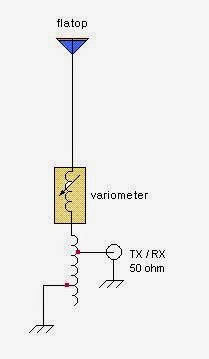
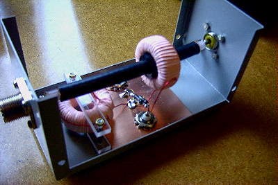
Several years ago, when I first set up my 2200m (136KHz) station under Industry Canada's Amateur Experimental Licensing Program, I utilized a fairly simple method shown in the LF Handbook, of attempting to tune and load my antenna. I had built a small top-loaded wire vertical consisting of a two-wire 50' flattop at the top end of a 30' vertical wire. A large loading coil of about 3 mH at the base of the antenna took care of getting the system close to resonance. As shown below, a variometer was used to fine-tune the system to resonance while the antenna impedance was matched to 50 ohms by tapping up from the base of the loading coil.
A 2A RF ammeter was used to monitor antenna current, with the plan being to tune and tap for maximum antenna current. It was the first time I had done any LF antenna work like this so it was a true 'learn as you go' project. It sounded fairly simple in theory but actual implementation was more challenging than I thought. What I also should have had was an LF SWR meter in the 50 ohm line as tuning and tapping for maximum antenna current did not guarantee that my system was indeed resonant or impedance matched. As you can imagine, there was much interaction between the two adjustments and I often found myself chasing my tail.
There were some tuning combinations that would peg the RF ammeter, indicating more current than my system was even capable of producing into a 50 ohm load. No doubt my settings were sufficiently 'off track' to create some diabolical impedance / off-resonance combination. I eventually settled on something that looked close but I was never really sure. Several weeks later I built the 'Scopematch' (designed by Jim Moritz -'MØBMU) and have not had a problem tuning and matching ever since.
Of all the devices in my LF toolbox, the most valuable by far is my Scopematch. Basically, it is a coupling device that allows you to monitor the tuning parameters of your LF antenna system. In real time, you are able to see both the impedance condition and the resonance tuning condition by observing the antenna current and voltage waveforms on a dual-trace oscilloscope. It is immediately apparent if your system is impedance matched (or not) and how close to resonance the system is. It will even tell you if your antenna is capacitive and requires more inductance to lower the frequency or if it is inductive and requires less loading inductance to bring it up in frequency.
Besides the dual-trace scope, the Scopematch requires only three parts and is fairly non-frequency critical. I am able to use it on both 2200m and 600m without any changes. More details to follow.
 |
| My homebrew Scopematch |
HFI gates QRT
I have taken down my HFAPRS gates. The reason is they all use my MFJ magnetic loop antenna. At this time of the year it needs constant retuning due to temperature variations in the loft. So it is not practical to use it when I can not be in the shack to tweak the turning .


