Archive for the ‘antenna’ Category
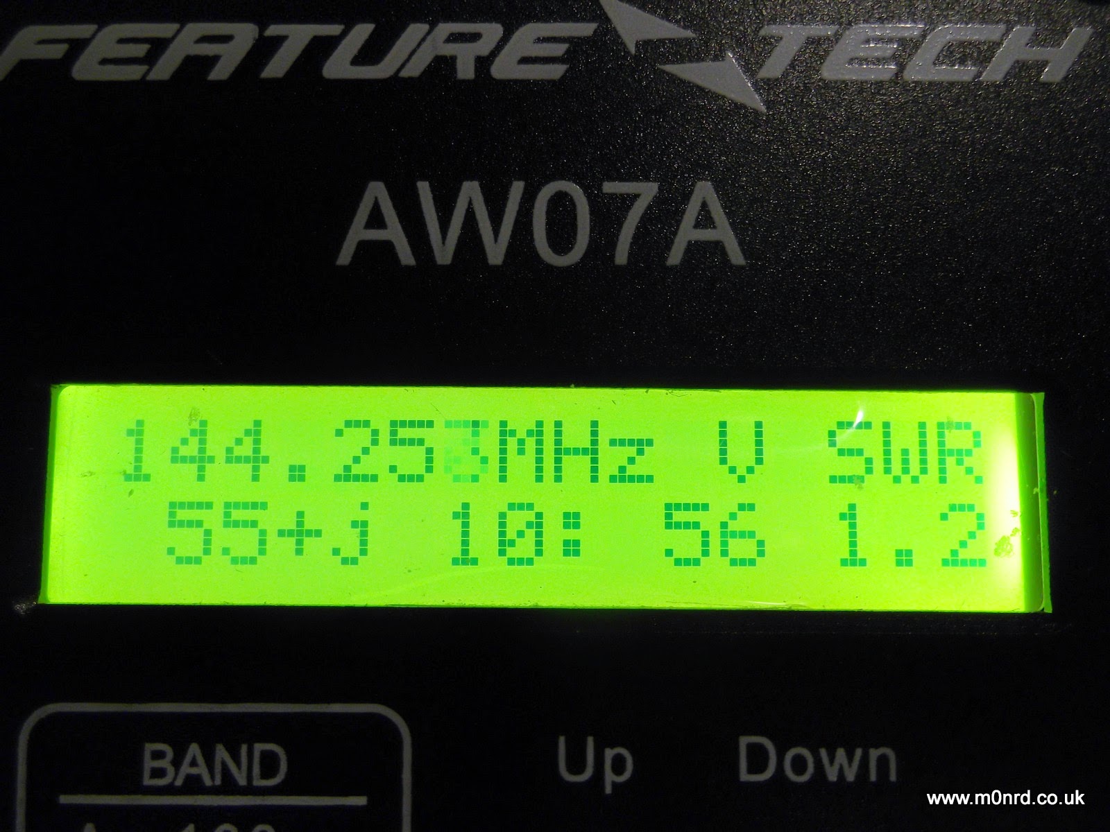
 Feature Tech AW07A Antenna Analyser – First impressions
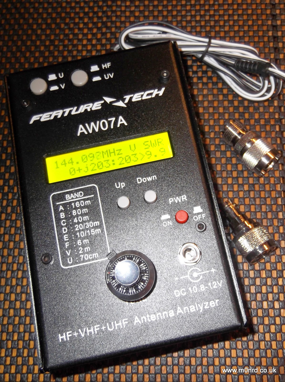
It is about the size of a thick paperback book and is a powder coated steel case similar in style to that used by MFJ equipment, indeed the MFJ-266 analyser appears to be a re-badged version albeit for a lot more money than this unit can be purchased.
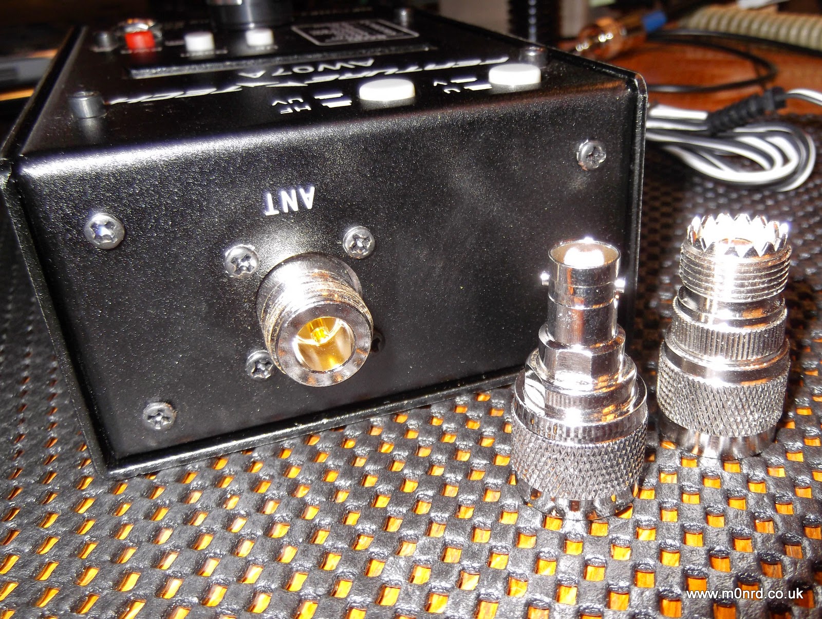
It can be powered by batteries fitted internally or by an external supply and is supplied with a power cable for connection to an external supply, mine was white/black rather than the normal red/black cable. It has a N-Type socket for the antenna and comes with two adapters for PL259 and BNC connectors.
It has a power button near the external power socket, two buttons on the top select HF and VHF/UHF operation and two other buttons marked UP and DOWN to select operating mode and/or the frequency band being used. Unfortunately one thing it doesn't come with is a manual but a copy can be downloaded from QSL.net or a slightly different version from the manufacturers website. But I actually downloaded the manual for the MFJ-226 has it is much more detailed.
The front panel decal and manual state it can be run from 10.8-12V, in fact the manual states it should ideally be less than 12.5V and no more than 13V. While doing some research I found the reason for this limitation hidden away on this aliexpress webpage "Avoid higher than 13V power supply circuit for the UV segment may be damaged due to excessive power dissipation." So this would seem to rule out using a standard 13.8V power supply.
It can be fitted internally with eight AA batteries and this is the way most people would use as it offers portability. Removing four screws allows access to the battery compartment and the internals electronics seem well built.
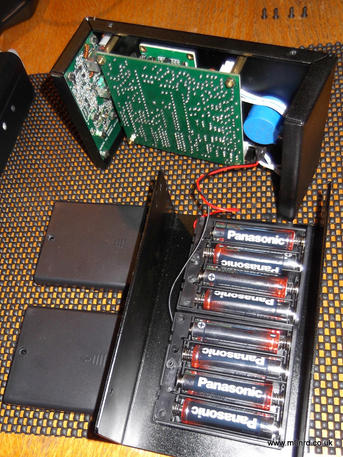
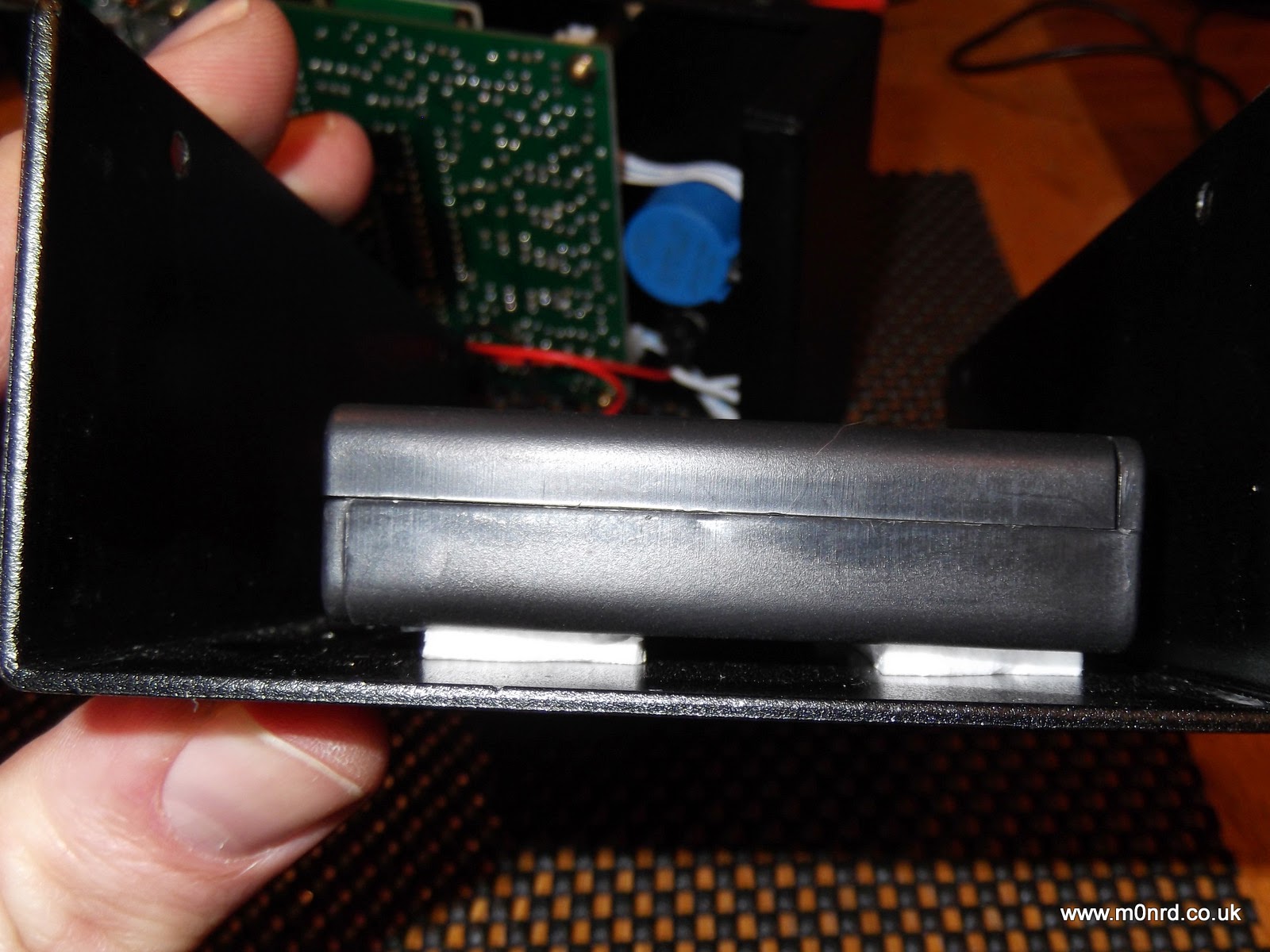
It takes eight AA batteries, in two boxes. The battery boxes have lids secured with a small screws and are fixed to the case using simple sticky pads, while secure at the moment I can imagine in time the adhesive could dry-out and become unstuck leaving the battery boxes loose inside the unit.
The display is a simple two line LCD with an optional bright back light which can be turned on during the power up sequence. The display shows the battery or supply voltage and pressing Down puts the unit into a frequency counter mode. Pressing Up puts into the antenna analyser mode.

In the analyser mode it is a simple case of selecting the HF, VHF or UHF mode. VHF works from 85-185MHz, UHF is 300-390MHz, the HF is split into six overlapping bands A: 1.5-2.7 MHz B: 2.5-4.8 MHz C: 4.6-9.6 MHz D: 8.5-18.7 MHz E: 17.3-39 MHz F: 33.7-71 MHz selected using the Up/Down buttons.
Turning the vernier tuning knob adjusts the generated frequency the antenna is being tested against. I connected the analyser to my 2m YAGI antenna and turned the knob to find the lowest SWR

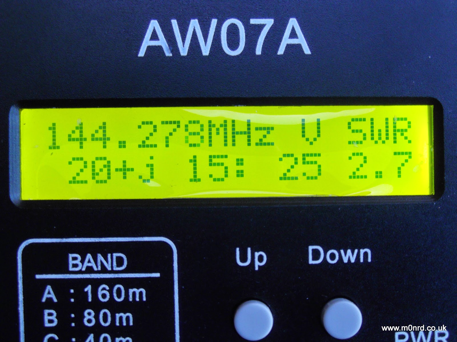
The manual describes what is being displayed (on UHF just the SWR is shown)
“139.763 MHz” is the frequency
“V “is the band (A,B,C,D,E,F in HF, V in VHF and U in UHF)
The bottom row shows the complex impedance Z = R + jX, so on this screen
“41” represents R = 41 ohms the resistive component
“18:” represents the reactance component value, jX = 18 ohms
“45” is the overall complex impedance magnitude Z = 45 ohms
“1.5” is the SWR value
As you can see for a 2m antenna something isn't quite right! The antennas were down due to last weeks strong winds so I was taking the opportunity to do some maintenance and tweaking of the 2m antenna since I'd seen an increase in the SWR during recent UKAC contests. I had suspected feeder issues, possible water ingress but I tried a dummy load at the antenna end but that read as expected (Z=50ohms) and metering the continuity of the feeder showed no issues, it just seemed to be resonant at too low a frequency.
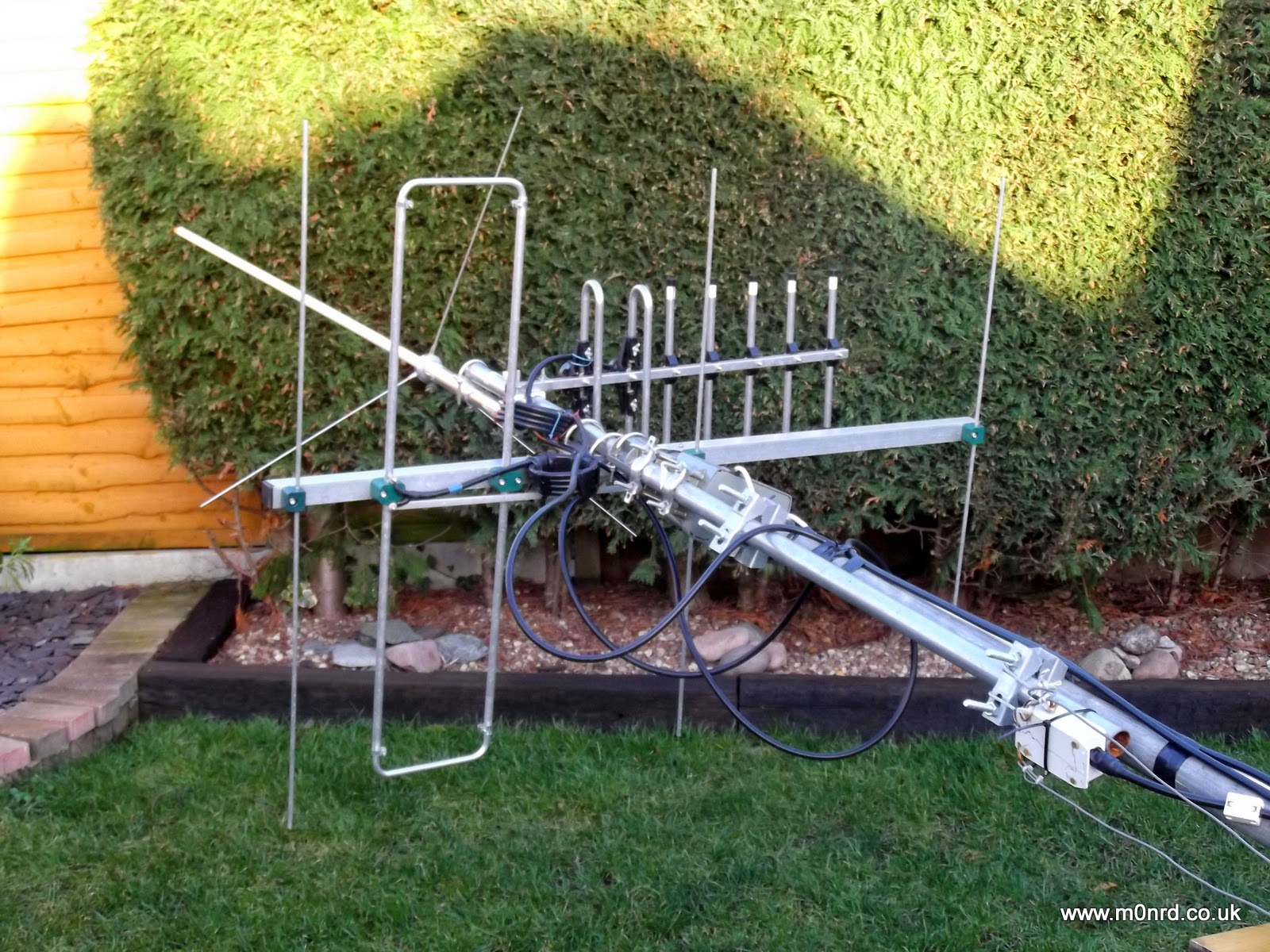
The analyser confirmed what I'd observed with a normal SWR/Power meter a higher than desired SWR in the middle of the SSB section of the 2m band.
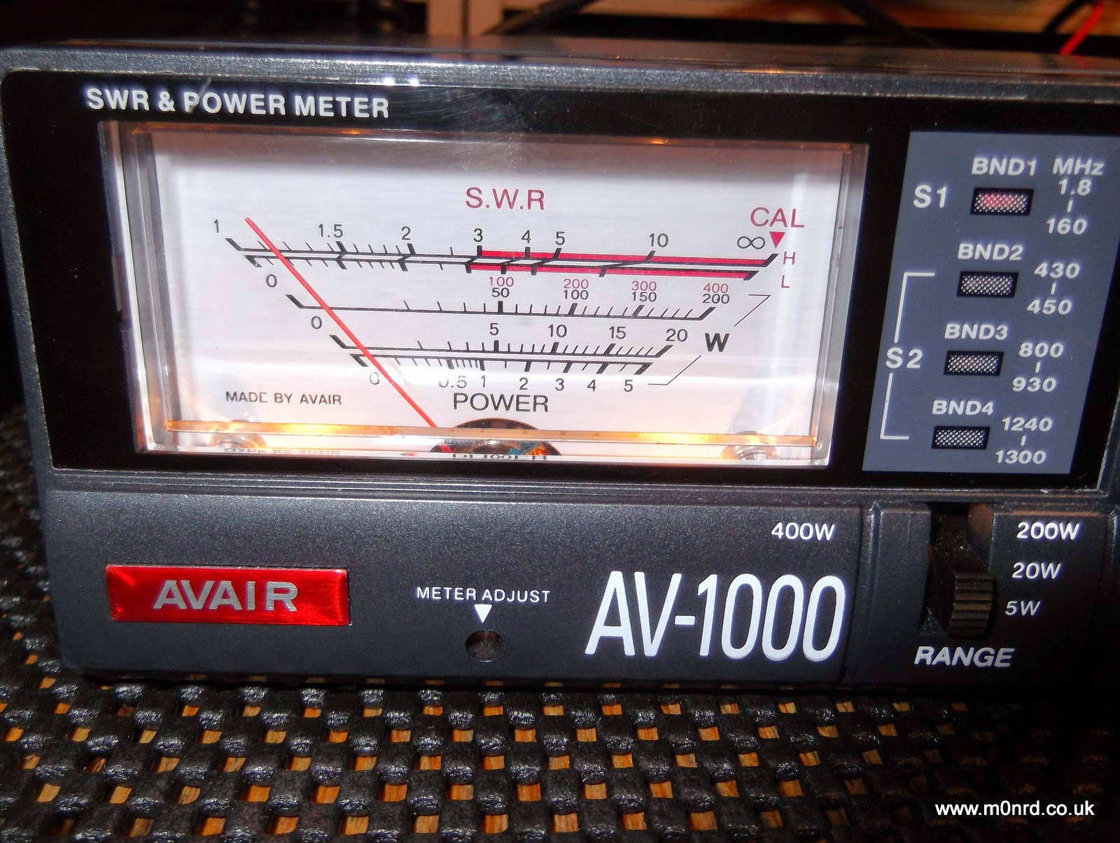
Unfortunately I was unable to get it any lower than 2.5 and most adjustments seemed to increase the SWR. For peace of mind I double checked the analyser by swapping the feeder on to the 2m/70cm collinear and that was spot on
again I double checked the SWR readings back in the shack using the normal meter
While I try to sort out the antenna issue I can say the analyser seems to do its job well. The tuning knob is a little twitchy and has a bit of play which makes setting the frequency accurately a little harder than it should be but hopefully that might improve with use.
The unit also has other functions none of which I have used yet but it is bonus to have some useful test functions available in the shack.
The AW07A can be used as an inductance/capacitance meter by powering it up with the U or D button held down. The inductance or capacitance of a component fitted across the antenna socket is then displayed and this can be done for any test frequency by selecting the band and turning the tuning knob.
As I mentioned earlier the unit can also function as a frequency counter that can measure signals between 1 and 500 MHz and can be used to give an indication of relative RF field strength. A signal source or an external antenna that yields a usable signal level may be connected to the analyser’s antenna jack. The usable signal range is quoted as -20dBm (30mV) to +10dBm (1V). Note that the display reading is a RMS value.
Obviously in the antenna analyser mode the output which is approximately 2V in magnitude can be used as a signal source, with 20dB of second harmonic suppression.
The MFJ manual goes into some detail of how this all works and how to use the analyser for a number of common tasks such as checking baluns, making 1/4wave stubs or measuring velocity factor of coax.
While the AW07A has some obvious shortcomings and may not be a precision device I am impressed with it and what it can seemingly do. It is shame about the lack of a manual but I am not sure getting one is justification for the premium price of the near identical MFJ unit.
My Latest Contraption, a QRP portable, all in one, seat & table, etc!

I added a bungee cord on each end to prevent damage from the radio accidentally falling off the table.
 The cord does not touch the buttons.

View from the back

All in one, QRP seat, table, umbrella and antenna anchor! The bottle on the table is bug spray! LOL

The table is a cutting board attached to the existing shelf.
The cutting board is bigger than the existing shelf, so I have more room for logging and a sturdy place to attach the antenna!
A bungee cord takes up the slack from the antenna in the wind. In a real world test, I found that one radial is all I need.
I tried an experiment, adding two, then four radials. There was no detectable change in signal level by ear on or the S meter.
One radial did the trick, and 4 radials didn’t improve the signal at all.

Note the guy ropes. This is to hold the chair in place. The golf umbrella is stuffed into a piece of PVC pipe.
The PVC pipe is tied to the chair with cable ties.
Wind and the antenna pulling on the table would easily turn the chair over.

Satisfaction! I can’t wait for the next ham radio outing with my QRP buddies.
Microvert antenna
Quite a few people who use WSPR use the tiny Microvert Antenna whose design seems to have originated in Germany. For example, this diminutive antenna is only about 30cms long on 28MHz. It uses the coax intentionally as a counterpoise with an RF choke the right distance down the coax. Performance is several S points down on a full sized antenna like a 1/2 wave dipole. With small antennas there is always a compromise! Versions have been made for most HF bands. The antenna looks ideal for portable or balcony use, being small and easy to erect. Perhaps I should test my (currently poor) build skills by making one for 10m or 20m WSPR use?
I wonder who reading this post has used a Microvert Antenna and how they found it?
See http://download.antennex.com/preview/archive4/Apr601/microvert.pdf .
New band tried with "compromise" antenna.
This afternoon I tried 80m WSPR with the “compromise” antenna (V2000 + 2m halo with strapped feeders) with some success. On 80m I copied M0BLP and PA0WMR although there were very few stations active. I was not copied by anyone. I was going to try 160m but decided there was too little activity.
Later I used 40m and 20m with the Par end-fed. On 40m, just one transmission resulted in 10 spots in 7 countries. The next transmission resulted in not a single report, probably because I was sitting on the frequency of a very strong station who was TXing at the time?
I later returned to 10m, and spotted EA5CYA (1376km) and LZ1OI (2145km) by Es around teatime. The Spanish station was pretty strong but the LZ was much weaker.
Antenna Update
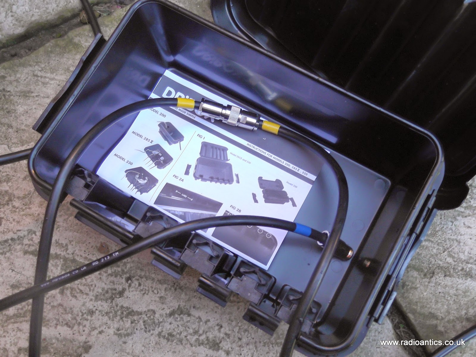
I have now got a coax run through the wall into the shack, with another to follow soon. To facilitate 'switching' between multiple aerials I have fitted each aerial with a length of coax running down the pole, terminating in an in-line N-type socket near the base. It is a simple case of connecting the appropriate shack coax, fitted with a n-type plug, to the appropriate socket.
To keep everything water and weatherproof I have opted for a DRi-BOX. These are inexpensive plastic boxes sold as waterproof housings for outdoor electrical installations such as garden or Christmas lights.
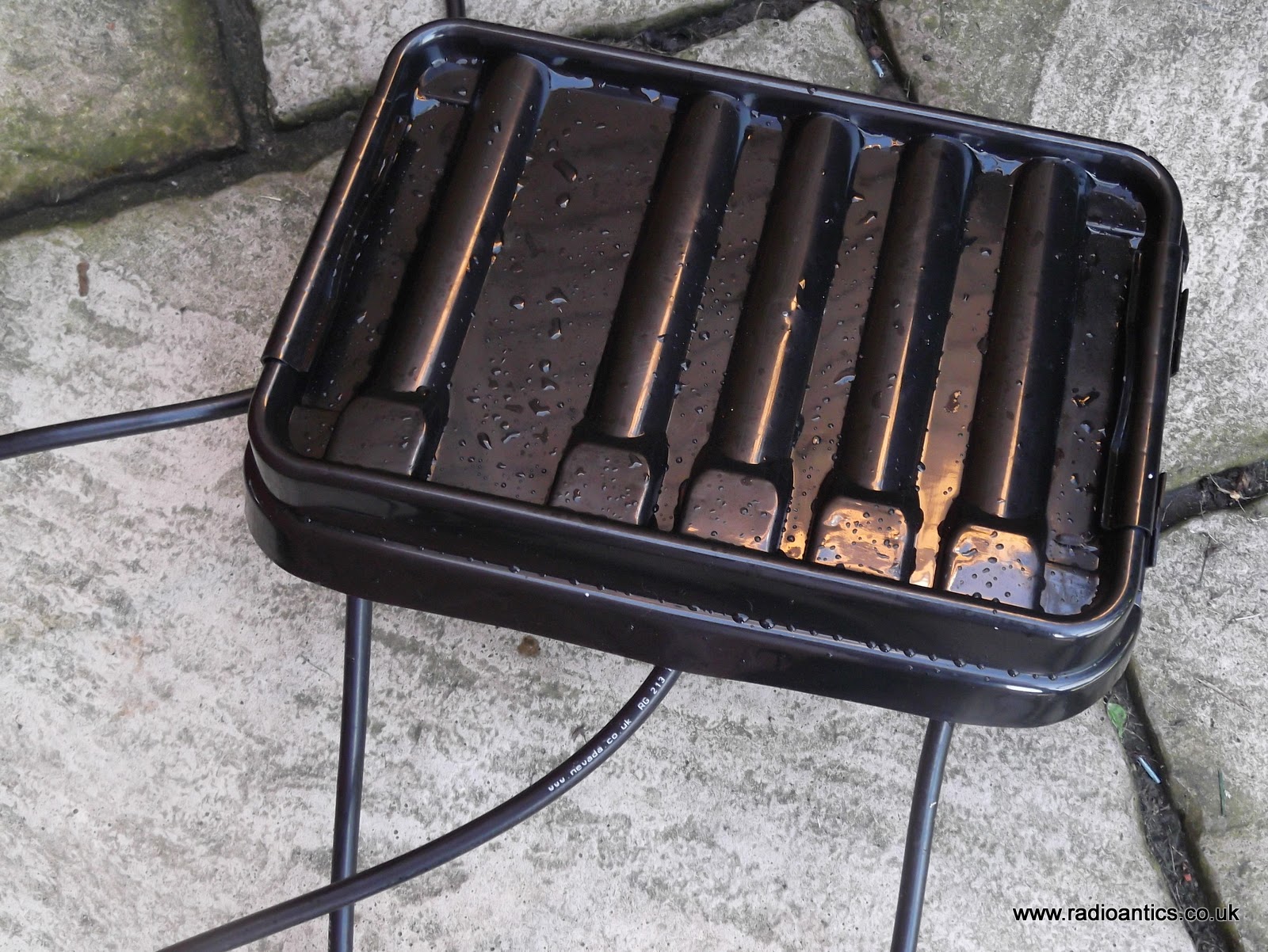
The lid has a silicon seal and there are a number of cable entry points with a flexible seal. When the lid is firmly clamped securely in place the box is effectivly watertight.
It is a bit of a fiddle with the thick RG213 but it seems to work well. There was a vicious thunderstorm and downpour yesterday afternoon and the Dribox lived up to its claims after sitting in a few inches of water.
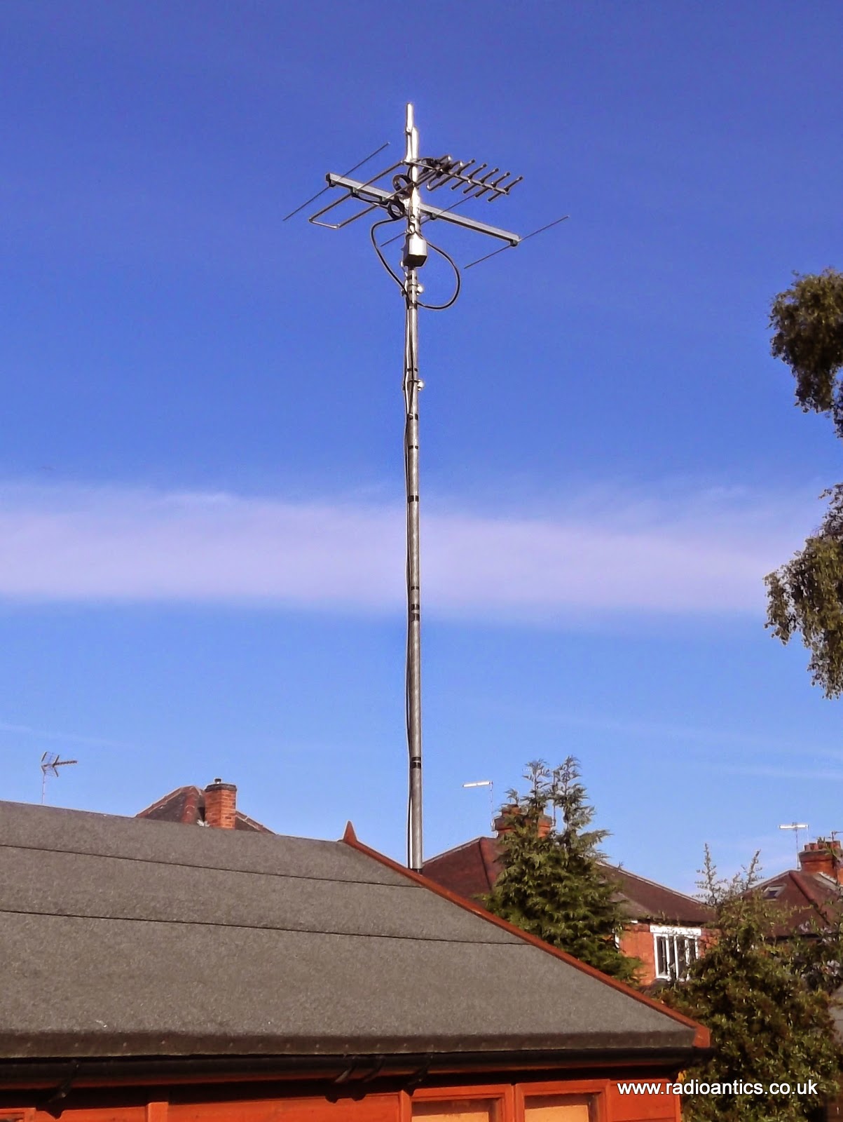 |
| Still awaiting the X-50 collinear on the top! |
Tuning around prior to the start of the contest and the band seemed quiet, hearing just a strong local operator. The contest start time passed and I was met with a wall of static only hearing the occasional very weak signal. I tried unplugging and reconnecting plugs, new patch lead, took the VSWR/Power meter out with no effect after 20 minutes I gave up. I decided something was obviously wrong with my new installation at the top of the pole.
I went back into the house where the wife was watching some dreadful house/diy/makeover program on TV which I could only manage for about 15 minutes. Grumpily I went upstairs and fired up the FUNCube Dongle and twitter and realised I'd forgotten and completely missed the first pass of the newly launched UKube-1, unlike some lucky ones. Idly I tuned to 70cm using the discone in the loft and could see a waterfall of signals! Including that local operator with a lot of splatter considering he was running just 10W
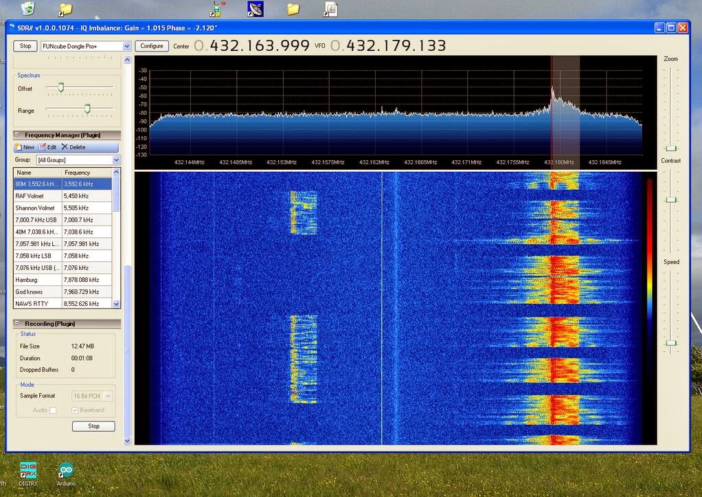
Going back into the shack and things had improved, so perhaps it wasn't my setup! After missing nearly a hour I searched and pounced again, just making 14 contacts but achieved my highest score so far for a 432MHz UKAC contest, still operating as M6GTG in the low power section.
Various operators have commented on the weird/poor/flat conditions last night, so perhaps I shouldn't have been so dismissive of my ability to put up a decent antenna!
The best laid schemes o’ Mice an’ Men
The best laid schemes o' Mice an' Men, Gang aft agley,That sums up my weekend perfectly.
An' lea'e us nought but grief an' pain, For promis'd joy!
After becoming licensed my eagerness got the better of me and in a moment of weakness I'd purchased a couple of 10m ready made cables from a major supplier only to discover quite quickly they were made from low grade RG58 coax (you can literally count the number of strands in the braid) and the connectors while serviceable were so poorly fitted they fell off!
 |
| James that PL259 has fallen off again! |
I had refitted the connectors using some solder this time and had managed to blag a 20m length of good quality RG58 (this actually has some braid) and I am ashamed to say these cables have been the weak link in my set up for far too long and needed to be upgraded.
I also needed to sort out the mounting for my aerials. Up till now I have been using a 5 meter telescopic painting pole that had cost around £16 from B&Q, it was okay when I was just clamping one aerial at a time to it but with the purchase of the rotator I has been chancing my luck with the loading, narrowly avoiding catastrophe when pushing the pole. I also couldn't fully extend the top section as the tube and joint were potentially weak. It was guyed quite well but was far from aesthetically pleasing, even in the summer sunshine!
 |
| 6M Moxon up on temporary pole |
Never fear I had a plan, a 20ft (6m) scaffold pole bolted using swivel joints on to to an another pole concreted in the ground in the back garden. The garden was extensively landscaped a few years back but it was before I became licensed, so I hadn't planned ahead. With careful negotiations with the station manager I secured a location where I could put it.
Thanks to my local handy man I now have two 10ft scaffold poles, sunk to a depth of nearly 5ft and encased in concrete in the corner of the lawn. A few inches of soil was left on the top to allow the grass to grow. They have been left for over a fortnight to completely set.
 |
| Scaffold pole sunk in ground |
I ordered a 100M reel of RG213 coax from Nevada Radio along with plenty of high quality N-Type connectors and various clamps and intended to sort out my antenna set up this weekend and banish the abysmal RG58 coax and PL259 connectors to some dark corner of the shack.
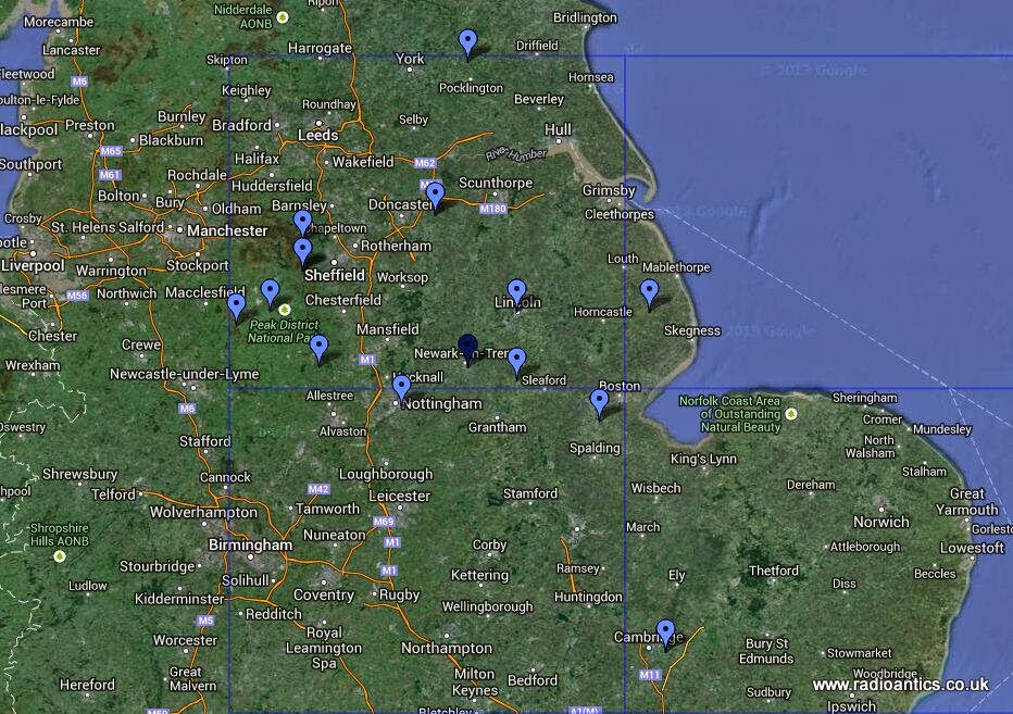
Before I took everything down on Saturday I managed to make contact with GB0TDF the special event station being run by the Denby Dale Radio Society from Cartworth Moor, Holmfirth for the Tour de France Grand Départ
A few months back I picked up a cheap rotator at the Dambusters Hamfest. It is designed for television aerials and isn't heavy duty but I was sure it would cope turning with the small 2M, 70cm Yagi and a 6M antenna on the same pole, with the X-50 collinear on the very top. However I was concerned by the potential lateral loading.
The rotator is a generic design and I spotted that an optional support bearing is available as an accessory. I chanced on one via Ham Radio Deals and had salvaged several good lengths of galvanised pole from a skip where I work. So the plan arrangement was as shown.. simple right?
 |
| Planned arrangement |
It turned it a frustrating morning after cutting the metal pole to length, bolting and clamping everything together I tested it at ground level with no antennas and the rotator refused to turn correctly and I narrowly avoided burning it out.
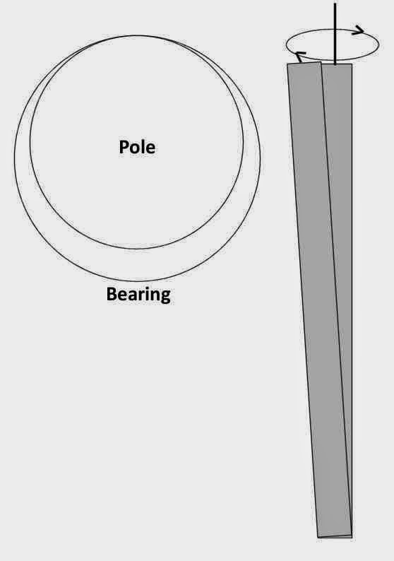
I checked poles and they were true, the rotator was free running as was the bearing. I unbolted, fettled and just couldn't make it work. I went away and had a beer while watching some of the Tour de France on the TV and in a moment of clarity realised what the issue was.
The problem was the diameter of the salvaged pole I was using. It was was slightly narrower (a couple of millimetres) than the hole in the bearing. I'd assumed it would line up with the rotator as it was similarly clamped, however when all clamped up top and bottom the pole wasn't perfectly perpendicular and wouldn't turn due to the eccentricity, Hopefully the drawing illustrates the problem.
Annoyed by this basic school-boy error I reverted to Plan-B for the short term, no support bearing! I was in bad mood now and so decided to leave the rewiring to another day. So I quickly put the 2M yagi on the existing coax as a test on the new scaffold pole to make a few contacts for the VHF NFD.
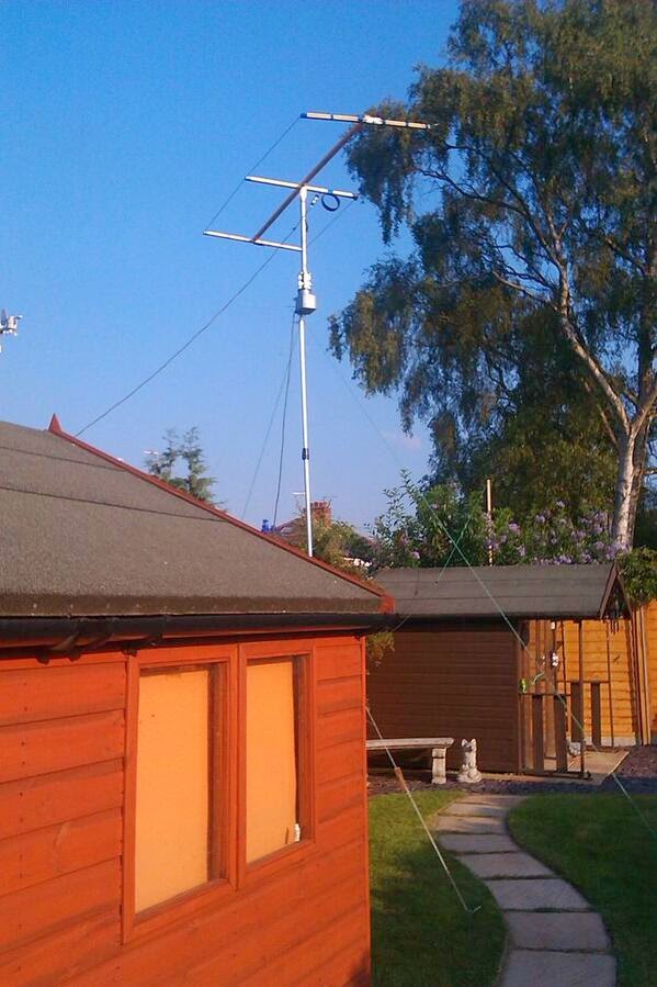
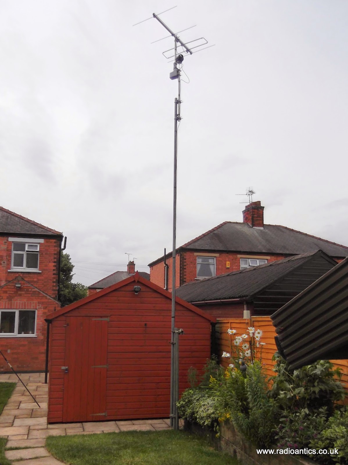 |
| Temporary installation to test scaffold pole |
Walking up the scaffold pole is straight forward, I have bolted a small cut off of scaffold across the top of support poles to act as a safety stop, lowering it likewise easy and I will certainly build up the muscles!
I managed to grab just 8 QSOs but was otherwise engaged for the rest of the weekend, however I was encouraged by the distances.
A few 2M QSOs during the NFD, Tour de France, Grand Prix and fixing a dripping tap took priority ;-) pic.twitter.com/BECaepRIlu
— Andrew Garratt (@nerdsville) July 6, 2014 I hope to get the 70cm antenna up tonight on the RG513 ready for the 432MHz UKAC on Tuesday evening.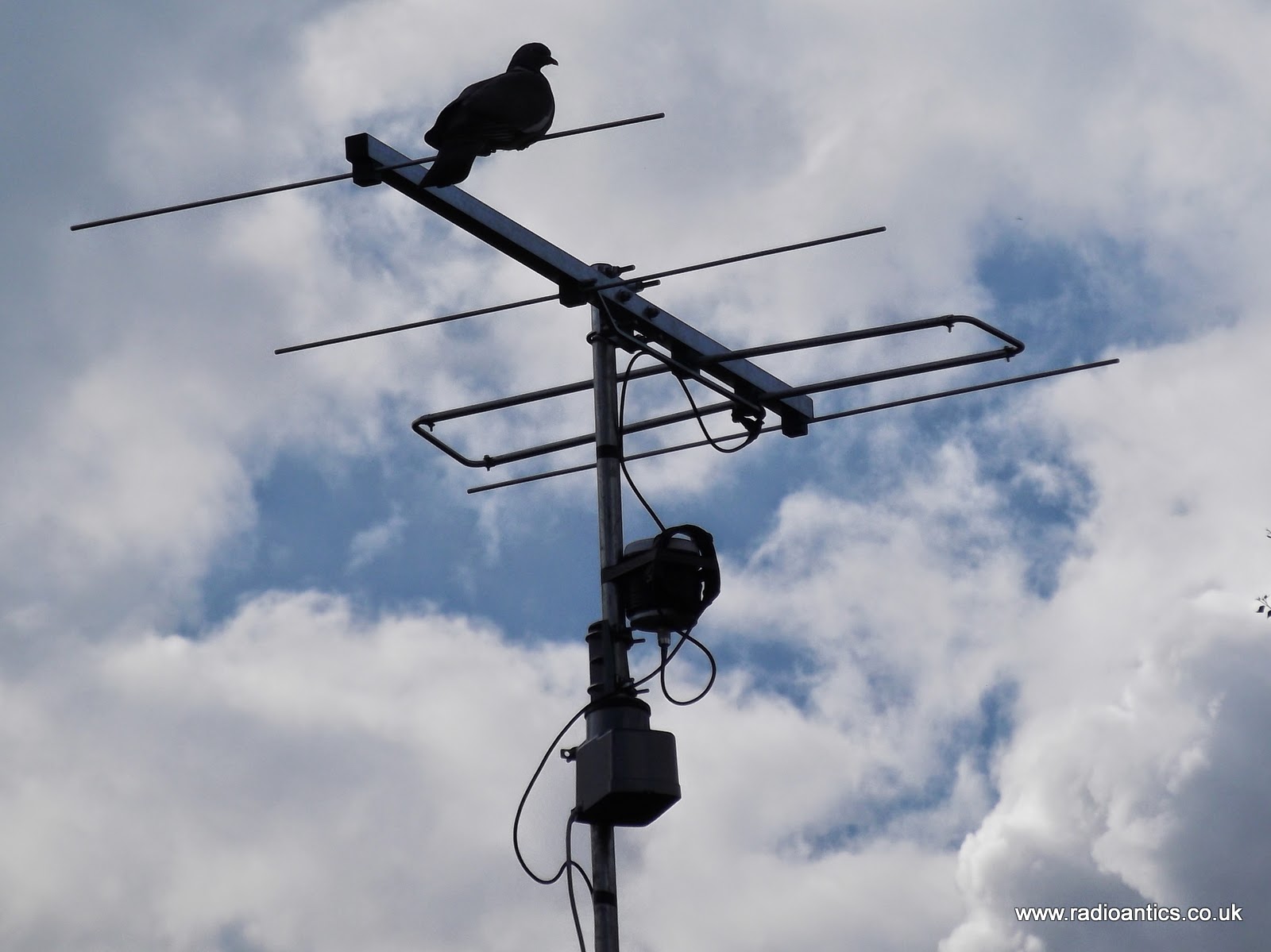 |
| The birds like the new setup |
Space Weather, HF Radio Propagation – The Interview on ‘Ham Radio Now’
Why would an amateur radio operator be interested in space weather? Is it worth the time and resources to forecast propagation, in the daily operation of a typical ham radio station?
Gary, host of the popular ‘Ham Radio Now’ video podcast, talks with Tomas Hood (NW7US), propagation and space weather columnist for CQ Amateur Radio Magazine (and in the late ‘Popular Communications Magazine’ as well as ‘CQ VHF Quarterly Magazine’) and The Spectrum Monitor Magazine. Gary discusses with Tomas how scientists forecast space weather, and how the average ham radio operator can also make predictions, and what propagation forecasting can bring to the daily operations of an amateur radio enthusiast.
Watch on YouTube: ‘Ham Radio Now’ Episode 156: Propagation…

Tomas, NW7US, talks about radio propagation on shortwave (HF) as well as space weather.


