Author Archive
 630m CW Activity
 |
| John - KB5NJD talks about his favorite topic, 630m |
New experimental licensee, Jim, WI2XJG in Saint George, Utah, recently posted a question on the Lowfer reflector regarding the status of his favorite mode (CW) on the 630m band. The detailed response, provided by John KB5NJD / WG2XIQ, may well be of interest to others as well:
Hi Jim,
Most regular CW QSO's are occurring from about 472.5 to 475 kHz. Note that in Europe 472.5 kHz is a popular frequency. My freq of choice when open is 474.5 because it puts my signals close enough to the WSPR passband that operators there may be alerted to my activity. It seems its become commonplace to use "CW-USB" receive pass bands unlike other low bands that default to "CW-LSB" (At the end of the day it doesn't matter as long as you know since carrier frequencies are what are typically announced).
As mentioned in previous communications much of the CW activity is by sked arranged either via the reflectors like this or the ON4KST chat or even
direct email. While random CW QSO's are not out of the question they are
rare during the summer as activity is decreased in spite of continued
propagation. YMMV. In the past I have mentioned how it might be
beneficial for you to listen to and decode some WSPR to determine the
current state of the band. Regular CW typically requires about -10 dB S/N
in a 500 Hz BW to make a QSO. If you are not receiving stations at -10 dB
or better, you may not hear any CW from that station.
If you live near an area of high activity, of course, this can be a
different result. As I mentioned before I maintain a daily CW sked at
1030z on 474.5 kHz as wx allows but your ability to hear it, particularly
during the summer may be severely compromised. Even those with very good receive antenna systems like NO3M / WG2XJM in Pennsylvania fight the noise this time of year and it can be hit or miss. I think Eric and I had a
total of two QSO's last summer and they were tough. Winter is a different
story and most nights, poor conditions and QSB aside, could yield a CW
ragchew over that same 1300 mile path. In the Winter I get many reports
from stations across North America that are scanning the band and hear the activity. Its not necessarily too different from operating habits on 160m
in that respect.
Activity nights in the Fall and Winter often yield lots of activity as they
have in previous years and those are announced on the reflectors and often
get a mention in QST a few months before.
As for CW activity in Utah, a good start might be Mike, AI8Z / WD2XSH/12
near Denver, Colorado. Mike has a nice signal and you may be able to catch
him on the 600mrg reflector. Also the guys in the Pacific Northwest are
active but I would strongly advise for you to listen to and decode their
WSPRs first to see what your capabilities really are. Your distance from
the PNW is not much different from your distance to me in Texas.
CW speeds will vary with conditions just as other bands. Good signals and
operators can mean fast CW and those same ops under poor conditions may have to slow it down.
JT9 activity is typically on 474.2 kHz USB dial and "carriers" are
typically between 1000 and 1300 Hz up but this varies. JT9 activity has
been low since we have moved into Spring and much of that is due to
abbreviated operating schedules that result from persistent poor weather
conditions. JT9 will require -24 dB to -27 dB S/N minimums typically for
QSO's and may be a good place for you to start, particularly if you arrange
a sked. I don't see much success from a random CQ on JT9 this time of year
unless guys know you are going to be there. Winter is another story and
guys often watch for signals in the waterfall pretty closely. Announcing
your operating intentions is still a good idea so that guys steer RX
antennas your direction.
Best advice I can give right now is to use WSPR to evaluate your station
(RX now and RX/TX when granted) and band conditions at any given time. It will save you a lot of potential frustration later.
Thanks JD and list for the 630-meter bandwidth!
73!
John KB5NJD / WG2XIQ
John and others continue to maintain vigilance on the 630m band nightly and his 630m web pages remain the best source of up-to-date information on band happenings and progress to final acquisition of the band for U.S. amateurs. If you are thinking of getting on 630m now, or later, a visit to John's site will supply you with a ton of motivation!
For Canadians, that already have the 630m band as well as 2200m, I am trying to keep track of Canadian activity here. As well, there has been much information on 630m published on this blog and looking here will bring up all of the 630m related blog posts.
Hunting For NDB’s In CLE 207
 |
| 'LU' - 214 kHz Abbotsford, BC |
This coming weekend will see another CLE challenge, this time in the LF band from 275 - 425 kHz. with a bit of a twist.
'CLE's' are 'Co-ordinated Listening Events', and NDB DXers around the world focus their listening time on one small slice of the NDB spectrum but this time around, the challenge has been expanded.
From CLE coordinator Brian Keyte (G3SIA), comes the following reminder:
Hello all,
Our special 'Channels Challenge' listening event is nearly here:
Days: Friday 27 May - Monday 30 May
Times: Start and end at midday, your LOCAL time
Range: 275 kHz (or 325) - 425 kHz (see below)
Target: Try to log ANY ONE NDB in each channel
The main challenge is to try and log ONE NDB on each of the 151
channels in the range from 275 kHz up to 425 kHz inclusive.
The 'channel' means the NDB's NOMINAL (published) frequency
(it may not be quite where you heard the Morse ident).
An NDB on a 'half frequency' would be OK. E.g. 345.5 kHz would
count as OK for channel 345, etc. - show it in your log as 345.5 kHz.
Each NDB must be a 'normal' one - no DGPS, NAVTEX or amateur.
If you hear any UNIDs, please show them in a separate list.
So it means a highest possible target of 151 CLE loggings in all - that
will be VERY difficult to reach, probably impossible away from Europe.
If you don't have much time, or if you want to avoid those tough
frequencies shared with DGPS, you can try a reduced challenge of
325-425 kHz. That would give a possible total of 101 NDBs, still VERY
hard for most of us to achieve.
When we first tried this in CLE170 (end of May 2013) the average number
of channels heard was 83 for Europe listeners, and 41 for Rest of the World.
If you have extra time and want to make the challenge more interesting
you could hunt for NDBs which:
# give you the greatest number of DIFFERENT RADIO COUNTRIES heard.
See our Countries list at http://www.ndblist.info/beacons/countrylist.pdf
(Each State/Province in USA, CAN and AUS is a separate radio country)
# OR give the greatest TOTAL DISTANCE from you to all of the NDBs.
# OR include the greatest number of CHANNELS WITH MIDDAY LOGGINGS
i.e. heard within 2 hours of midday by your local winter clock time.
Send your 'Final' CLE log to the List, if possible as a plain text email
(not in an attachment) with CLE207 at the start of its title.
Please show on EVERY LINE of your log:
# The full date or day no. e.g. '2016-05-27' or '27'
and UTC (the day changes at 00:00 UTC).
# kHz - the beacon's nominal published frequency.
# The Call Ident.
Show those main items FIRST on every line, before other optional details
such as Location, Distance, Offsets, Cycle times, etc.
Always tell us your location and brief details of your receiver, aerial, etc.
I will send the usual 'Any More Logs?' email at about 17:00 UTC on
Tuesday so that you can check that your log has been found OK.
Do make sure that your log has arrived on the List at the very latest
by 08:00 UTC on Wednesday 1 June.
I hope to complete making our combined results on that day.
Good hunting,
Brian
----------------------------------------------------------
From: Brian Keyte G3SIA ndbcle'at'gmail.com
Location: Surrey, SE England (CLE co-ordinator)
----------------------------------------------------------
TIPS!
Try the channels from 325 kHz first - if you start on the more difficult
lower frequencies it might dim your enthusiasm!
As always, you can find advice about CLEs generally and about this
special one by visiting our CLE page: http://www.ndblist.info/cle.htm
This time you won't need a normal seeklist to help you. However,
from our CLE page you could quickly display details of the NDBs on
a particular channel using REU, RNA or RWW as appropriate to you.
Just enter e.g. 345 - 345.5 in the frequencies boxes and click 'Go'.
(REU shows, for example, that hearing an NDB from England on 287
would be a 'first' since 1990!)
If you wish you could use any one remote receiver (e.g. Twente) for
your loggings stating the location and owner - with their permission
if required. A remote listener may NOT also use another receiver,
whether local or remote, to obtain further loggings for the same CLE.
These listening events serve several purposes. They:
- determine, worldwide, which beacons are actually in service and on-the-air so the online database can be kept up-to-date
- determine, worldwide, which beacons are out-of-service or have gone silent since the last CLE covering this range
- will indicate the state of propagation conditions at the various participant locations
- will give you an indication of how well your LF/MF receiving system is working
- give participants a fun yet challenging activity to keep their listening skills honed
Final details can be found at the NDB List website, and worldwide results, for every participant, will be posted there a few days after the event. If you are a member of the ndblist Group, results will also be e-mailed and posted there.
The very active Yahoo ndblist Group is a great place to learn more about the 'Art of NDB DXing' or to meet other listeners in your region. There is a lot of good information available there and new members are always very welcome.
If you are contemplating getting started on 630m, listening for NDBs is an excellent way to test out your receive capabilities as there are several NDBs located near this part of the spectrum.
You need not be an ndblist member to participate in the CLEs and all reports, no matter how small, are of much value to the organizers. 'First-time' logs are always VERY welcome!
Reports may be sent to the ndblist or e-mailed to either myself or CLE co- ordinator, Brian Keyte (G3SIA), whose address appears above.
Please ... give the CLE a try ... then let us know what NDB's can be heard from your location! Your report can then be added to the worldwide database to help keep it up-to-date.
__._,_.___
630m Transverter Project
 I've ordered parts from Digikey for the summer workbench project, a 630m transverter. With the nice 630m WSPR signals received here from Roger (VK4YB) this spring, I think it might be possible for us to work each other using JT9, if the path continues to improve over the next few seasons. On more than one night, Roger's signal was at JT9 QSO levels and had we been on a schedule, a QSO may have happened. Roger's signal was peaking late in his evening, which for me will require making schedules in the wee hours of the morning.
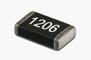
I've been wanting to build another SMD project for some time since making a little SMK-1 40m transceiver several years ago. This was a very inexpensive kit put out by the NorCal QRP Club as a way of introducing SMD construction techniques to beginners. I found working with the 1206 sized parts (basically the largest ones commonly available) to be fairly laborious and would only solder a few parts at a time before setting it aside for the next day. I think my frustration had a lot to do with my positioning and soldering methods and I'm anxious to try doing it with a more refined technique. As I recall, there were 72 SMD components on the board and it took me a couple of weeks to finish it all.
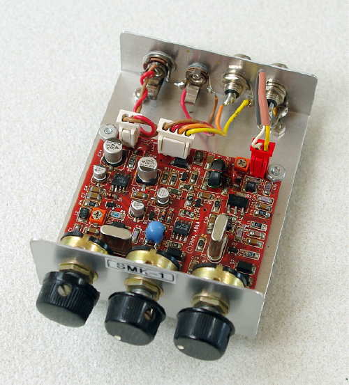 |
| My SMK-1 40m SMD transceiver |
The parts I have ordered are also 1206 sized but the older I get, the smaller these things seem to look. The transverter will be based partially on the popular G3XBM circuit but will eliminate the PA. Instead, I'll just use a few volts of the transverted squarewave signal and a doubler, so that I can feed the signal directly into my present homebrew amplifier which uses two switching FET modules into a power combiner. Hopefully this system will let me run several of the non-linear digital modes such as WSPR, JT9, JT65 etc.
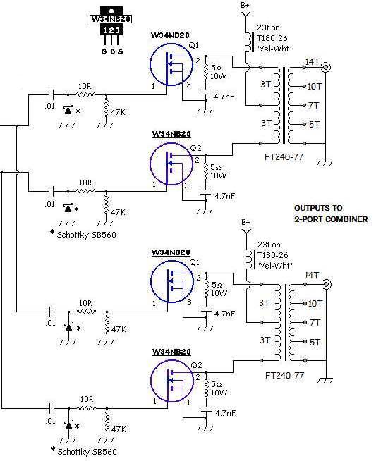 |
| My 630m PA |
As a way of getting back into the SMD-soldering groove, I have ordered and now received, an "SMD Practice Kit" from E-Bay ... a real bargain at $1.78!
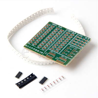 |
| courtesy: Tradeworld2105 |
Although there are many similar practice kits being offered on E-Bay, this was the only one I found that had two IC's to practice with ... all of the others had just one. Since the transverter's doubler circuit has an IC chip, a couple of practice opportunities will be helpful. My only hope is that I don't run out of SMD steam with the practice board before getting down to the actual transverter board.
As soon as the parts arrive from Digikey, I'll start designing the transverter's PCB ... but with all of the usual distractions of summer, as well as trying to maintain vigilance on the magic band once again, my summer project may not progress as quickly as I hope.
All of this assumes that my old eyeballs hold out as well.
Lightwave Madness
 |
| The 288 km path courtesy: REAST |
One of the local lightwave builders, Mark (VA7MM), brought my attention to some outstanding lightwave work conducted several years ago, by a group of very dedicated amateurs in Tasmania.
A pair of articles describes their successful attempts to send signals, via cloudbounce, over the astounding distance of 288km (180mi), crossing Bass Strait between the north Tasmanian coast and southern Australia.
What did it take to transmit lightwave signals over such a distance? Basically a system similar to the ones recently employed in our own local lightwave experiments but on a grander scale ... much grander!
The receiver is based on one of the KA7OEI designs, with modifications to increase its sensitivity. The receiver, and several other designs, can be found on Clint's website here, probably the best source of information on amateur lightwave available anywhere.
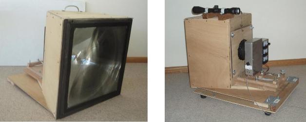 |
| The lightwave receiver courtesy: REAST |
 |
| The 10mm x 10mm rx APD courtesy: Hamamatsu |
The transmitter was also big, consisting of an array of 60 red Luxeon III LED's, similar to the Red Rebel Luxeons used in our own local tests. Each LED had its own 12cm square fresnel lens, heatsink and method of focusing. Certainly this was a mammoth project, by amateur lightwave standards.
 |
| The 60 LED TX array courtesy: REAST |
Earlier long-haul tests out to 209 km used the digital JT65 mode for signal decodes but the 288 km test used a fairly esoteric weak signal mode called WSC built on the Spectrum Lab software. This mode is capable of digging almost 20 db deeper into the noise than JT65, down to almost -50db.
An in depth description of the two long-haul events, including equipment schematics, can be found in "288 km Cloudbounce from Tasmania to the Australian Mainland" and in "209 km with Narrow Beamwidth Transmitter".
The 288 km crossing project evolved over several years and is all very well documented, from the first early steps, at the Radio and Electronics Association of Southern Tasmania's (REAST) website here.
This adventuresome project was largely the work of VK7MO, VK7JG, VK3HZ and VK7TW. Their work is most inspiring and much can be learned from seeing what they discovered when transmitting into the cloudy nighttime skies.
Such an endeavour as this makes the local, much shorter Georgia Strait crossing, seem like a cake-walk, but I can't imagine using anything that big and bright here without causing trouble ... it would probably appear much too 'laser-like' to talk one's way out of a jam. Pointing anything resembling a laser light into the air these days is simply begging for trouble.
I can however, envision a scaled-down version, perhaps consisting of an array of four Luxeons ... at least on my end of the path, but even pointing one of those from the city could be problematic. Perhaps any NLOS lightwave attempts across Georgia Strait will need to be well away from Vancouver and its two-million sets of eyes.
VE7CNF’s Lightwave Cloubounce / Scatter Tests
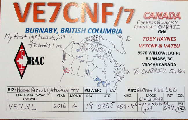
After our recent lightwave CW QSO, described here, Toby (VE7CNF) has been re-focusing on refining his lightwave system for weak signal non-line-of-sight (NLOS) cloudbounce and scatter mode experiments.
His testing to date has been limited to within his own suburban yard, with the transmitter being set up on the south side of the house and the receiver set up on the north, while basically pointing things straight up.
Several tests have already been done with exciting results, including audible CW being returned from a low (5,000') cloud ceiling and weaker returns noted on clear air scatter but readily detected in the CW QRSS mode. Toby has also interfaced his PC audio, via amplifier and FET driver, to enable him to use WSPR and JT9 modes, resulting in positive signal returns using these two digital modes of modulation.
Toby described some of his results and methodology in a recent e-mail updater:
I've done some lightwave backscatter experiments this last week. The transmitter is on my front deck, pointed straight up as verified using a level across the lens end of the box. The receiver is in the back yard and pointed up also. Between the two, the house is about 30ft high and blocks any direct light.
Last night May 8 UTC was clear and I was getting a QRSS10 level signal with the receiver pointed at elevations from 70 to 85 degrees, through the transmitter beam. There was nothing received from straight up, so the clouds were too high for cloud backscatter. At 80 degrees elevation I got the best signal. I've attached an Argo screen grab of QRSS10 (FSK CW with the 570 Hz tone as key-down).
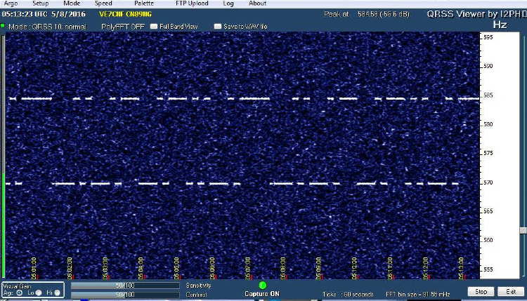 |
| QRSS10 CW clear air scatter return signal |
WSPR2 was decoding consistently and JT9 was about 70%. I tried JT65, BPSK31, and MFSK8 but the SNR was too low for those to work.
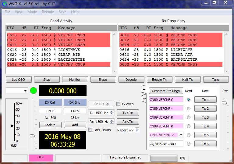 |
| JT9 cloudbounce return signal 14,000 - 24,000 FT |
May 8, 2016 UTC CYVR clouds and temperature/dewpoint data:
0500 FEW CLOUDS (1/8 - 2/8) 14000 FT, SCATTERED CLOUDS (3/8 - 4/8) 24000 FT, 14 C / 11 C
0600 FEW CLOUDS (1/8 - 2/8) 14000 FT, SCATTERED CLOUDS (3/8 - 4/8) 24000 FT, 14 C / 9 C
0700 FEW CLOUDS (1/8 - 2/8) 12000 FT, FEW CLOUDS (1/8 - 2/8) 22000 FT, 13 C / 7 C
... I'll try CW and digital again when there's some lower cloud conditions. That’s tough to get without rain at the same time.
I did get dew on the receiver last night, so I'll be adding heating resistors inside the boxes to keep the lenses warm. Electric heating has worked great to keep dew off the optical surfaces of my telescope. I'll also look at adding shrouds to shield the lenses from the cold sky.
More from May 15th:
Last night was good for backscatter from low clouds, at 1300 to 1900 ft according to airport weather. I had to stay up late though, as the cloud didn't move in until midnight.
I've attached a couple of CW recordings. Early on the signal was weaker with QSB. Later it was strong and solid.
I've also attached a screen grab of WSPR2. Signals were up around 0dB this time.
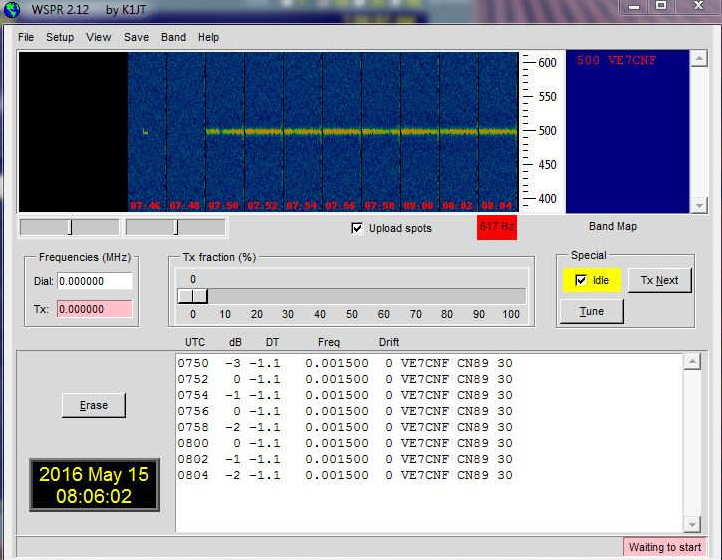 |
| WSPR cloudbounce return signals 1300 - 1900 FT |
I played with a bunch of digital modes and FMHELL and SSTV. Everything was working pretty well off the clouds.
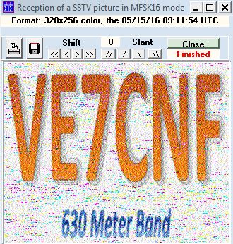 |
| SSTV cloudbounce return signal |
The nextstep is to move the rx farther from home, then to try sending signals over to John or Steve by cloud bounce.
Toby's nearest lightwave neighbour, VA7MM, is in mid-build and is working to complete a system capable of running overnight cloudbounce / scatter tests between their two respective backyards ... the NLOS distance is about 15 km. Although the path includes some bright commercial lighting QRM, with narrow-band modes such as QRSS or WSPR, it may not be a problem. I suspect one of the biggest problems will be getting suitable weather as, here on the west coast, dense clouds usually turn into rain very quickly, especially near the coastal mountains where Toby and Mark are located.
I find Toby's results to be both encouraging and exciting! It will be interesting to try some cloudbounce between their respective stations and my own and maybe hopping the NLOS path across cloudy Georgia Strait. It may well be possible to do this in one of the quicker QRSS CW modes such as QRSS3 or QRSS10, both of which can have fairly fast exchanges of the required information (calls, signal report and final confirmations). Failing that, slower QRSS30 or one of the weak signal digital modes such as JT9 / WSPR which have the ability to dig deep (-30db) into the background noise may be the answer ... there is much to learn yet!
The ZL1SIX Ocean Floater

For those of you that are fans of the low-powered "party balloon" floaters, such as the recent S-9 flight by VE3KCL, now comes a different kind of floater and one that really does float ... on the Pacific Ocean!
The "Ocean Floater" is the work of Bob, ZL1RS, who has been very active in tracking the other floaters from his excellent receiving site down-under. Like the balloons, Bob's beacon also utilizes the QRP Labs U3S hardware to transmit data in both WSPR and JT9 modes. The little beacon runs ~100mw on the 30m WSPR band and tracking this one will likely be a bit more challenging than following the high-flying balloons.
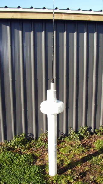 |
| Bob's 'Ocean Floater courtesy: http://www.qsl.net/zl1rs/oceanfloater.html |
Here is Bob's description as he posted to Yahoo Groups QRP Labs:
A small project inspired by Hans' Voyager ideas at
http://www.hanssummers.com/voyager.html ... the Floater is a 100mW
transmitter on the 30m band with a short base-loaded whip antenna
mounted on a buoy that will drift in the Pacific Ocean. It is sending a
standard WSPR transmission once and hour, followed by two JT9
transmissions giving its position, the temperature, and the battery voltage.
The project was deliberately kept very simple. A QRP-Labs U3S
transmitter and firmware made the electronics side easy. The U3S was
rebuilt on a board with a more open layout to allow experimentation and
the addition of a PICAXE controller to switch things on/off as required
to reduce overall battery consumption. Most of the "hard work" was in
the buoy body and antenna. More information about how this went
together can be found at http://www.qsl.net/zl1rs/oceanfloater.html
Today the Floater left on the yacht Windflower to be released into the
south-west Pacific Ocean in a few days time. This will ensure the
Floater is well clear of the coastal currents around ZL that would
otherwise have 'beached' it along the coast if it been launched from the
shore. Unlike balloon flights, things will happen very very slowly, so
updates to the webpage and tracking map will probably only be made on a
daily basis. WSPRnet spots will show the 4 character Maidenhead
locator position, and the JT9 decodes have a 6 character Maidenhead
resolution. Any JT9 decodes you receive will be appreciated via e-mail
to [email protected]
73, Bob ZL1RS
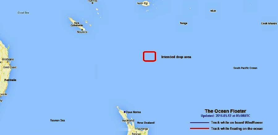
The beacon will use the call "ZL1SIX" and will be launched shortly, near Minerva Reef. Watch Bob's website for tracking and updates and ... good luck Bob!
IC-7300 LF / MF Receive Performance
 | ||
| courtesy: Icom's youtube |
Finbar recently had the opportunity to borrow and test-drive a spanking new Icom IC-7300. Like many of those interested in the LF / MF bands, he was particularly curious about its receiving performance in this part of the spectrum. His present mainstay LF receiver is the Icom R-75, which by any standard, is an excellent performer on the broadcast band and below.
Here are Finbar's anecdotal observations made with a borrowed IC-7300:
" ... my nearest radio amateur friend really surprised
me yesterday by telling me he had bought the new Icom 7300 SDR
transceiver. He offered me a quick loan to try it out. I drove the 9 km
straight away and getting home set it up side by side with my Icom R75.
3 hours later I returned it to it's owner having gained a valuable
chance to test it.
First off, he forgot to give me the instruction manual, but after a
short interval I had it sorted out, having seen the numerous videos, on line.
I disabled the MW attenuation and made sure not to have the Pre-amps
on, otherwise, within the medium wave band, it becomes very messy,
as one would expect.
Basically my R75 produced sharper, more sensitivity in the NDB band,
with some signals on the Icom 7300 being very weak to unreadable,
whereas the Icom R75 gave a much more solid signal, on those very weak
signals.
I did not test the rig on short wave, nor did I transmit or even key
it up, in any mode. I was much more interested in it's apparent receive
capabilities.
I will not be buying an Icom 7300, my Icom R75 is just fine and a
great receiver.
Don't get me wrong, the 7300 is a fine set, but as I see it, it
is the first of this new generation of non PC based SDR sets, and very welcome, at that. However the screen is just too small and crowded. Anyone used to a Perseus screen would be irritated by the sheer volume of screen and sub screen, all of which deserve a proper amount of space.
The subsequent new SDR based transceivers by both Icom and other
set makers, will I expect, contain a larger screen, together with an
ability to feed the video screen into to a PC type monitor, yet
allowing the user to use an SDR type transceiver or receiver without being tied down to a PC.
I look forward to these more comprehensive sets coming on the market.
This is just the beginning of a new phase in receiver and transceiver
SDR technology, integrated in the sets without a lumbering PC having to be
run alongside. This will be a breath of fresh air. Bring it on."
Although I don't believe this is the first non-PC based SDR transceiver, it may be the first 'entry-level' radio of this type. These are one ham's observations made over a short period with one particular unit and your experiences may be much different.
Finbar would be very interested in comments on his observations as well as comments on your own experience with the IC-7300's receiver on the LF bands.
The R-75, although now discontinued, still remains one of the best performing LF receivers, dollar-for-dollar, if you're still looking.
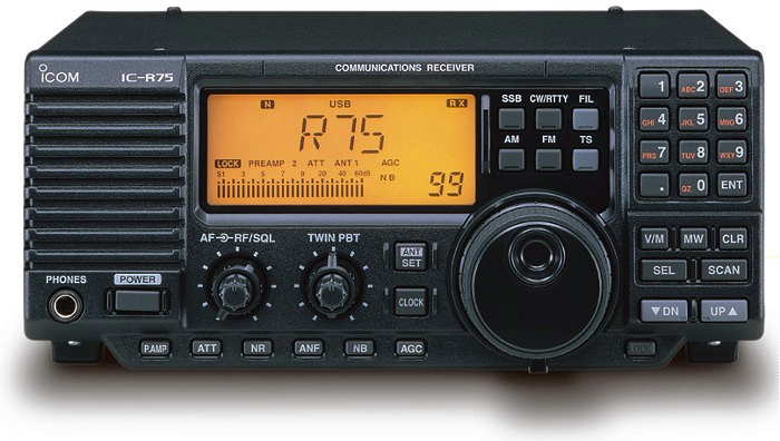 |
| Icom R-75 |
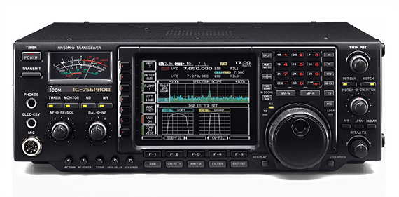
As well, from my own experience, I can vouch for the superb receive performance of the Icom 756 PRO III on the LF and MF bands.
 |
| courtesy: http://www.icomcanada.com |


