Author Archive
 Hunting For NDB’s In CLE 210
 |
| 'VR' - 266kHz |
This coming weekend will see another CLE challenge, this time in the MF band from 260 - 269.9 kHz plus 440 - 1740 kHz.
'CLE's' are 'Co-ordinated Listening Events', and NDB DXers around the world focus their listening time on one small slice of the NDB spectrum ... but this time around, the range has been expanded.
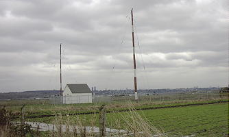
The lower frequency range covers one my very strong locals, 'VR' on 266 kHz. 'VR' is an outer marker approach to Vancouver International's 'two-sixes' and is located a few miles east of the main runways in a farmer's field. Although running just 50 watts, it is widely reported (as far east as North Carolina), probably due to the excellent soggy ground beneath its somewhat unusual delta-shaped loop.
From CLE coordinator Brian Keyte (G3SIA), via the Yahoo ndblist Group, comes the following reminder:
Hello all,
Our end-of-August Co-ordinated Listening Event will soon be here.
We'll be hunting for normal beacons in two contrasting frequency ranges
and there is also the possibility of hearing several amateur beacons.
As always, first-time CLE logs will be extra welcome.
Days: Friday 26 August - Monday 29 August
Times: Start and end at midday, your local time
Frequencies: 260.0 - 269.9 kHz
plus: 440.0 - 1740.0 kHz
These are interesting frequencies, the same ones that we last used for
CLE191 in February 2015 when 45 of us joined in.
Many of us should be able to hear beacons in both ranges, though Europe
only has a handful in the '260s'. From 440 onwards, North America has a
few, mostly around 520 kHz, while Eastern Europe has several beacons
and some regular UNIDs. Some of the NDBs can also be found among
Europe's Medium Wave Broadcast Stations.
Many of us are within range of amateur beacons on frequencies mainly
around 474 - 478 kHz. We'll be listening for ANYTHING OPERATING IN
BEACON MODE, preferably with normal speed Morse.
(We ask operators who sometimes use QRSS, PSK, WSPR, etc.,
which need software to receive them, to PLEASE CHOOSE THE
SIMPLER MODE during the CLE so that we shall all be able to
receive them and make reports).
Please look out for my final details with advice about log-making, etc.
in a few days.
73
Brian
----------------------------------------------------------
From: Brian Keyte G3SIA ndbcle'at'gmail.com
Location: Surrey, SE England (CLE co-ordinator)
----------------------------------------------------------
These listening events serve several purposes. They:
- determine, worldwide, which beacons are actually in service and on-the-air so the online database can be kept up-to-date
- determine, worldwide, which beacons are out-of-service or have gone silent since the last CLE covering this range
- will indicate the state of propagation conditions at the various participant locations
- will give you an indication of how well your LF/MF receiving system is working
- give participants a fun yet challenging activity to keep their listening skills honed
Final details can be found at the NDB List website, and worldwide results, for every participant, will be posted there a few days after the event. If you are a member of the ndblist Group, results will also be e-mailed and posted there.
The very active Yahoo ndblist Group is a great place to learn more about the 'Art of NDB DXing' or to meet other listeners in your region. There is a lot of good information available there and new members are always very welcome. As well, you can follow the results of other CLE participants from night to night as propagation is always an active topic of discussion.
If you are contemplating getting started on 630m, listening for NDBs is an excellent way to test out your receive capabilities as there are several NDBs located near this part of the spectrum.
You need not be an ndblist member to participate in the CLEs and all reports, no matter how small, are of much value to the organizers. 'First-time' logs are always VERY welcome!
Reports may be sent to the ndblist or e-mailed to either myself or CLE co- ordinator, Brian Keyte (G3SIA), whose address appears above.
Please ... give the CLE a try ... then let us know what NDB's can be heard from your location! Your report can then be added to the worldwide database to help keep it up-to-date.
JT65 Bringing New Activity To 50MHz
 |
| JT65 Waterfall |
As mentioned in previous blogs, this summer's Es season on 50MHz has seen a huge increase in the number of stations using the weak-signal JT65 mode.
Although this mode has been around for a few years, for some reason, it really took off this season. I witnessed many long-time, 'CW-forever' operators (myself included), gingerly move up the band to see what this mode could offer.
At first I thought the activity I was seeing was probably mostly from magic-band regulars, who like me, were also curious ... but I now think this is not the case.
Normally, my 6m summertime Es activities result in just one or two stations requesting a QSL to confirm the contact. These are usually guys that either need a VE7 card or are looking to confirm my grid-square ... just a few cards arrive, in spite of many dozens of contacts over the summer months. This summer I noticed a much different pattern.
This summer saw a tenfold increase in the number of QSL requests and every single one was for a JT65 or JT9 digital mode contact! It soon became apparent that these were not 6m diehards that had just moved up the band, but rather, very enthusiastic newcomers to the band ... what an exciting thing to see! Many of the cards did not have any grid-square information ... the telltale sign of all VHF operators. They had discovered the magicband, using JT65.
Perhaps these were mostly 'no-code' amateurs or those living in antenna-challenged situations such as condos or apartments. Whatever the reason, it really is interesting to see such a profound change in 6m operating tactics, by both the veteran ops and by the newcomers ... all happening so quickly. Hopefully some of the new arrivals will venture down the band to try CW or SSB where contacts can be made much more quickly than on the digital modes but all of this new activity is wonderful to see.
Remembering The ‘Woodpecker’
Those of you that have been hams for a long time will no doubt recall the Russian 'Woodpecker'. The 'Woodpecker' was a strong, fast repeating signal / racket that often wiped out amateur communications on 20m here in North America ... maybe other parts of the world as well.
Amateurs with yagis eventually determined that the signals (yes there was more than one it seemed) were coming from the USSR. The QRM was persistent and in spite of formal complaints being lodged via diplomatic channels, continued for many years ... from 1978- 1989. Some of the new transceivers built during the time actually had a 'WOODPECKER' position on the noise blanker switch, hopefully offering some relief to the problem.
For you younger folks, here's what Duga usually sounded like:
Several web searches brought up numerous descriptions of the Duga (Russian for 'arc' or 'bow') project, some with conflicting information. From what I can sort out, there were three Duga sites ... one near Chernobyl, another near Chernihiv and a third, much later, in Siberia. The first two (Duga and Duga-1) were in the Soviet Ukrainian SSR (now Ukraine) while the third was located near Komsolmosk-on-Amur in the Russian far east. One source indicates that the second Chernobyl site is often misidentified as the Duga-3 array and should be referred to as Duga-1, with Duga-2 being the Siberian location.
Initial speculation suggested this intrusive signal was some form of 'jammer' ... very common during the Cold War. It wasn't long before the true nature of Duga was thought more likely to be an 'over-the-horizon' (OTH) long-range radar system for detecting the launch of North American missiles aimed at the USSR. The three radar sites gave the Soviets good over-the-pole coverage as well as to the east, where it could also be utilized for tracking domestic rocket launches.
 |
| courtesy: http://www.globalsecurity.org/wmd/world/russia/steel-yard.htm |
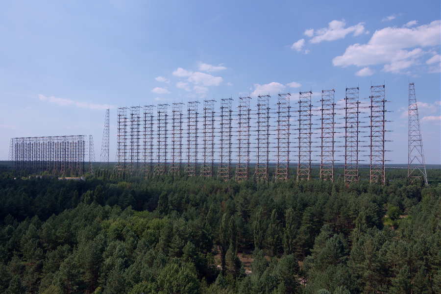
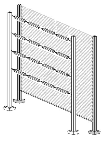
The antennas themselves appear to be phased dipole curtain arrays, commonly used in various configurations by shortwave HF broadcasters.
 |
| courtesy: http://www.antenna.be/hr.html |
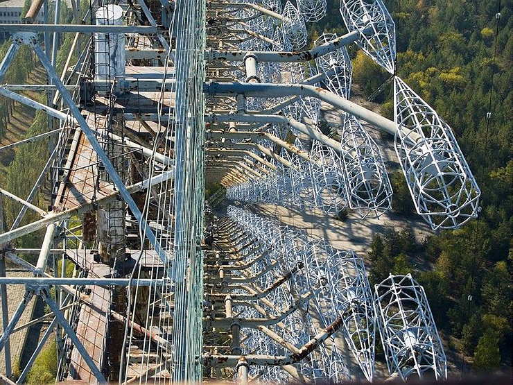
Each site was paired with a receiving array ... remember, this was a radar system, with two of the three systems having the receiving array located tens of kilometers from the transmitter. The Chernobyl Duga is said to have had the receiving antenna located on site. Sources discussing physical size indicate the dimensions for the receiving array to be larger than those of the transmitting antenna. It seems possible then, that the pictures and videos commonly found are those of the receiving array and not of the transmitting antenna. It might make sense to have more gain on 'receive' than on 'transmit' as echoes from small targets many thousands of miles away would not be easy to detect. No matter what the actual case, I can only imagine the fun of hooking up an HF transceiver to one of these arrays during a DX contest on 20m CW!
The Chernobyl site shows two arrays, side-by-side ... possibly the larger being that used for receiving and the smaller one for transmitting. This antenna has been noted as a 30/10/2 array ... 2 bays, 30 dipoles wide and 10 high, 600 elements in all!
Further research tends to indicate that each dipole is what is called a 'Nadanenko' dipole. The main feature of this style was its cage-styled construction, giving the element a large diameter resulting in a broad bandwidth.
 |
| courtesy: https://shema.info/en/antenna/ |
 |
| courtesy: englishrussia.com |
First, you see that there are two sets of arrays 15 driven elements wide by 10 driven elements high for a total of 600 elements! They are intermeshed and offset from each other by 1/2 wavelength both vertically and horizontally. There is a horizontal wire screen reflector behind the driven elements.
Some of the other things I noticed are ...
... you can see the open-wire feeds and reflector screen. Each set of collinear elements is fed individually with open wire line. There is a support line between each two bays of driven elements.
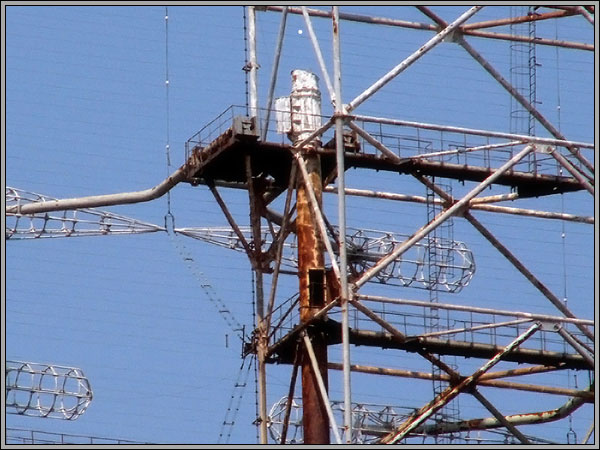
... that the reflector screen is supported on the sides by the stand-alone free-standing towers at each side of the array. (I had been wondering why they would have those towers next to the array like that. Now I know.)
... that the element supports are steel pipe instead of fiberglass (or something similar). Apparently, the shape of the radiators allows for the pipe supports to enter the element cages at the element low-impedance point which made the supports invisible to the antenna and also allowed for the supports to not radiate themselves.
 |
| courtesy: http://anzee.livejournal.com/65530.html |
The Duga system was operative between 7 and 19MHz, with 40kHz wide pulses, usually lasting for about seven minutes. The most common pulse rate was at ~10Hz but this sometimes varied. Power levels used often mention 10 megawatts but it's not clear if this was RF output, peak pulse power or ERP.
It's somewhat gratifying after all these years, to actually see close-up, where the Woodpecker signal started its journey around the world and to appreciate the superb engineering that went into these impressive structures ... but sad to see the last one in such a rusted state of decay and abandonment. It would be nice to hear it just one more time ... but please, only for a couple of minutes.
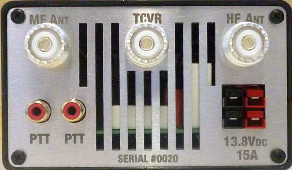
The New VK4YB 630m Transverter
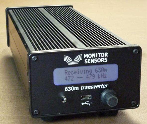
Now that beta testing is complete, production units are now ready for distribution from Monitor Sensors, a family environmental-sensor manufacturing company of which Roger is Governing Director.
The introduction of the VK4YB 630m Transverter presents another new option for those wishing to get on the band, or in the case of American amateurs, to get prepared for the band ... soon expected to be implemented in the U.S.
When I first started using the test unit provided, I was immediately impressed with how simple it was to set up and to get operational. It sits inconspicuously beside the main station's transceiver, taking up less space than the typical station speaker unit.
One usually associates 'transverter' operation with a rat's-nest of cabling or re-cabling to accommodate the new addition. The transverter arrived with all necessary cabling, even a nice Anderson power pole connector to connect the user-supplied 12V power source. A second pair of 12V contacts is also available for sharing with other station needs. One feature that I quickly appreciated was the dual RCA jack on the rear panel for controlling the transverter's PTT keying line. With my transceiver's PTT line already being used for another purpose, it was simply a matter of plugging-in (cable supplied) and sharing the line with the second jack ... no need for unplugging or using an external adapter to split the PTT line. Switching from 630m to normal HF operation is simply a matter of turning the transverter 'off' ... all HF operations are back to normal with antenna routing taken care of. There appears to be a lot of thoughtful engineering packed into this little box.
A look under the hood shows a well-planned and efficient use of space as seen in this pre-production prototype shown below. If Collins Radio were to manufacture a 630m transverter for the military, I can't imagine it being any better than this!
| prototype board under test |
"... we carefully match the FETs into three pairs. Each pair is matched to its opposite number but the pairs are chosen so 2 have low gain, 2 have mid gain and 2 have high gain. This improves the IPs and also the harmonics. With matched FETs we are getting the 2nd harmonic at typically -60dB. That's 10dB better than the stringent FCC requirement."
Roger's unit is running at 16 volts and produces 90W output, with his 630m WSPR signal being the one most often heard in North America from down under.
The transverter's multi-colored screen combines with a multi-function menu, allowing a visual on-screen display of numerous parameters such as RF output power, DC supply voltage and current draw, SWR, exciter drive power, heatsink temperature, graphic SWR display and various warning screens.
The transverter requires 3-5 watts of 160m drive from the station transceiver for full output power. Built-in safety circuits prevent overdrive from causing any damage. Similarly, transmitting into a high SWR or with no antenna connected is no cause for concern. Temperature sensors will trigger shutdown should the heatsink rise above 100 degrees C. Software also prevents out-of-band transmission.
This is a microprocessor controlled linear-transverter. This means that operating system software can be readily updated (via the supplied micro USB cable) as new features are implemented. It also means that any mode your transceiver is capable of operating on can be produced on 630m. At present, the most popular modes on the band are WSPR, CW and JT9 but I suspect this order may change once the band is opened up in the U.S.
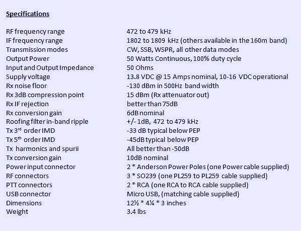
A shortened eight-page Operator's Manual can be downloaded from the Monitor Sensors web site but units will ship with a more comprehensive 22-page manual. For more information regarding pricing and shipping, please contact Monitor Sensors here. For technical questions, please contact Roger here.
Another Rare Visit From The ‘Snowman’

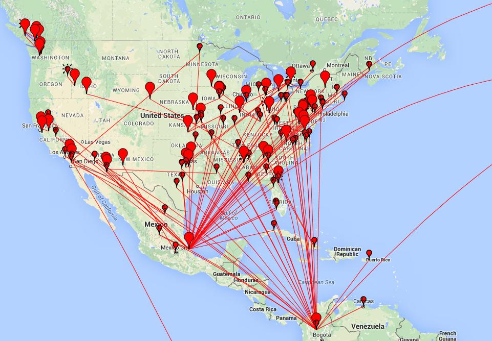
Thursday's blog lamenting this summer's poor domestic Sporadic-E season on 6m must have struck a sour note with the propagation gods as Saturday afternoon and evening saw a massive opening to the eastern U.S., Alaska as well as to the Canadian Arctic ... it was even strong enough to show up the next morning and continue on and off for most of the day. Now that's the type of thing we used to see with fair regularity and it was a welcome respite from what has generally been acknowledged, along with last summer, as the poorest Es seasons in many years. The long-lasting, strong-signal opening provided us dedicated 6m junkies with a nice late season flurry of fun, which would not have been out of place had it occurred in mid-June ... maybe the Es 'metamorphosis' eluded to in my last blog also includes an extension of the normal season. Who knows what effect global warming is having on this aspect of natural phenomenon ... there is just not enough yet known about this fascinating mode of propagation that generates so much interest every summer.
The map below shows the 'leftover' activity on Sunday morning ... not as much as Saturday night but still a pretty good showing for the last day of July!
 |
| courtesy: http://www.dxmaps.com/spots/map.php |
I spent most of my time working this opening on JT65, up at 50.276, and learning the ropes of this fast-growing mode. One thing is abundantly clear however ... ideally, the chosen JT mode for 6m Es should be JT9 and not JT65.
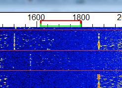
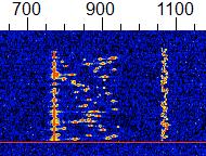
Using JT9 would allow 10 times the number of stations to fit into the present JT-window ... that's 100 JT9 stations instead of 10! With JT65, the window fills-up quickly and the QRM can soon take its toll with the usual ear-splitting strength of Es signals.The waterfall below shows the much narrower, more sensitive JT9 mode on the right compared with the wider JT65 signal on the left.
 |
| courtesy: https://sm7vrz.wordpress.com/jt9-english/ |
I took the opportunity to send out a few JT9 CQ's and did work a number of stations with several of them being well into the -20db range ... too weak for CW but readily worked on JT9. The sensitivity of JT9 will allow two-way contacts to be completed right down to the -27db range, over a one minute transmission period. This is pretty close to the popular WSPR none-QSO mode! I'm surprised that WSPR is so popular on HF when hams could actually be working each other, on-the-air in weak-signal mode JT, instead of relying on a backdoor computer link to see who is hearing their signals ... isn't two-way communication what it's all about? Granted, WSPR beaconing is great for observing propagation trends when you can't be there to watch, and therein lies its utility. Please excuse my short WSJT rant!
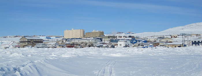
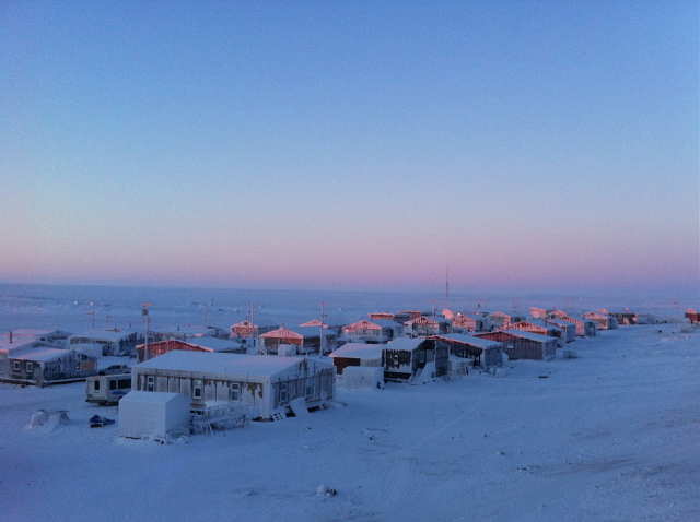
Saturday night's opening provided another rare visit from the 6m 'snowman' ... VYØSNO/b, located in Iqaluit, Nunavut in the Canadian Arctic. The beacon is rarely heard as far west as VE7 and it is always a great treat to catch it. It is basically unmaintained so when it fails, may never be repaired ... it's nice to know that its 25 W transmitter is still doing the job. I suspect that if anything fails, it will be the antenna in the brutal Arctic winter weather. The beacon's vertical antenna is located on the top of the high building on the left.
 |
| courtesy: https://en.m.wikipedia.org |
 |
| Sunset at VYØYHK courtesy: https://thesongiliveby.com |
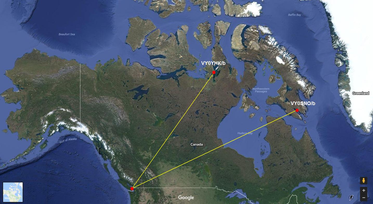 |
| courtesy: https://www.google.ca/maps |
This short video was made during Saturday evening's opening to the north and before the VYØYHK/b appeared. The weaker beacon on 50.030 is VY1DX in Whitehorse, Yukon Territory.
This morning, as I write this, the band is open to W1 and points to the east ... still some life left in the band yet.
It will be interesting to watch what happens over the next two weeks, when most Es activity on 6m usually folds its tent and quietly disappears until the following May ... let's hope the Fat Lady still needs more practice before pulling the curtain.
Magicband Morphs
I have been having fun on 6m every summer since the late 60's. Without doubt, this summer's Sporadic-E (Es) season is the worst one I have experienced in terms of domestic (North America) openings. This summer was almost a carbon-copy of last year's summer Es season. As I mentioned in an earlier blog, unless this is some form of short term or cyclical anomaly, the fundamental nature of Sporadic-E openings appears to be undergoing some type of change. Missing-in-action were the numerous day-long intense openings to California as well as the grand openings to the eastern states (FN grids) and Canada ... all guaranteed openings every summer. These openings would often last well into the late night hours and even overnight, picking up the next day where they left off. This is the second summer in a row where no Es MUF's into the 2m band were experienced, with this year having seen nothing even as high as the 88-108MHz FM band. Maybe I missed them if they occurred, but I don't think so.
In terms of non-domestic openings, the band continues to evolve, as it seems that a higher percentage of hours with very long skip continues to rise. As poor as this year has been domestically, CW contacts were completed with Germany, Ireland, England, Japan, France, Canary Islands, Balearic Island, Venezuela, Cuba, Puerto Rico, and the Cayman Islands. A short and exceptionally rare opening to Africa, allowed an 'almost QSO' with CN8KD in Morocco, as he had one letter of my call incorrect when he quickly faded away ... pretty exciting even for a 'busted' QSO on 6m, in the middle of summer. Whether this very long propagation is just multi-hop traditional Es or something entirely different is still up for debate, as often there are no indicators (beacons or other mid-point signals) indicating that the band is even open. Many, including myself, believe this is some form of chordal hop or interlayer ducting, involving the E-layer alone or perhaps even the bottom of the F layer. Signals strengths can reach 599 levels and almost without fail, have extremely small footprints, with stations just a few miles away hearing nothing at all.
When these openings occur between western North America and Europe, they can be very exciting, as the footprint on the European end often sprays around like a stray garden hose, popping up in a different country with each passing minute. Openings are often fast and furious and always heart-pounding! Perhaps there is still some magic yet to occur but the 'normal' season (or what used to be normal) is drawing to a close as August nears. The fat-lady is warming up her voice behind the curtain and will soon be singing once again. But something else is changing on 6m besides the propagation and that is the huge growth of the JT65 weak signal digital mode. As the season draws slowly down, I still see long-time dedicated CW operators going up the band to dip their toes for the first time on this alternate mode. I have used it fairly often to work stations when the CW / SSB end of the band appears to be dead. The maps shown below, grabbed just four days ago, illustrate what I have been seeing. The amount of JT65 activity is striking, compared to the traditional CW/SSB modes, both shown for the same one hour period. I could assume that the several extra db of weak-signal sensitivity is the reason for the disparity seen from one mode to the other but there may be other factors coming into play.
Once the band really opens however, the weak-signal sensitivity of JT65 soon looses its previous advantage and the JT65 segment of the band can get pretty clobbered, with numerous signals on top of each other, all competing for their ~200Hz slice of the spectrum. As well, a JT65 QSO is slow ... a minimum of four minutes. Taking four minutes to exchange calls, reports and 'rogers' on a wide open band with strong signals, makes little sense. Perhaps the majority of 6m JT65 operators are new amateurs with a codeless licence or are operating in antenna-restricted communities. Whatever the reason, the numbers are growing and traditional operating patterns are changing. Who knows what next summer will bring!
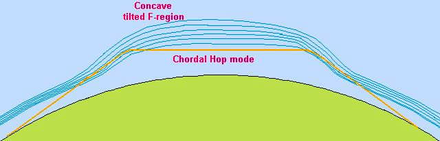 |
| Chordal Hop courtesy: http://g4fkh.co.uk/projects/lp-experiment/ |
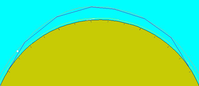 |
| Inter Layer Ducting courtesy: http://g4fkh.co.uk/projects/lp-experiment/ |
 |
| courtesy: http://www.dxmaps.com/ |
 |
| courtesy: https://pskreporter.info/pskmap.html |
Weak Signal Volume Levels
 A recent posting on Yahoo's Perseus SDR Group inquired about the use of external or PC-based DSP manipulation of signals partially masked by noise to improve readability. The most interesting part of this short discussion was the result of one response indicating:
"BTW one of the best and most simple noise reductions is to lower the volume."
to which the original inquirer responded:
"BTW, lower the volume to reduce noise ... ?? That was a joke, right ??"
Other comments soon followed, including my own, initially:
"Actually, for whatever reason, this works...at least when copying very very weak CW signals. I think it is more of an ear-brain thing where the noise
gets more focus than the signal when listening at moderate levels but
cranking everything down to a very low level has always improved copy for
me....not sure why this works as well as it does."
From Roelof Bakker, PAØRDT:
"The ear brain system works much better at low volume as it is easily
overloaded by strong signals. Similar like too much direct light in
your eyes will degrade contrast. I guess this is getting worse with
age, but I am not sure about that.
I have been watching many videos on YouTube which demonstrate ham
radio gear and most if not all use far to high volume settings,
which degrades readability. I believe it is a normal habit to raise
the volume for weak signals, but this is often contra productive.
When listening for weak signals at low volume settings, a quiet room
is mandatory. I have taken considerable effort in building a quiet
PC, that is aurally quiet.
What does wonders for copying weak signals with the PERSEUS is to
switch off the AGC."
"No it's not a joke and it's not the RF Gain. It's one of the capabilities of the human ear.
Of course qrm can be limited and reduced but noise is difficult. What you often see is that with all those noise reduction things is that the volume drops. Make an audio recording of a part with and without a (white) noise limiter switched on. Open it into an audio editor and you will see that the amplitude of the part where the noise reduction is on is lower. Now amplify that part to the same level as where the limiter is not active and play it back. You will be astonished how little the difference is.
It's probably also a thing that can differ from person to person but I've never seen tools that can make an unreadable signal readable. Most of the time they sound just different, not better."
Likely there is a ton of data showing how our ear / brain link deals with noise or tones buried in noise. With audio levels set to anything above bare minimum, I think it's very easy for your brain to react mainly to the noise and not to the tone. Reducing this level possibly puts the two back on even levels ... even though there really has been no change in signal-to-noise ratio.
When trying to copy very weak, difficult signals, I've always found that turning audio levels down to bare minimums helps me personally. As Roelof mentioned, the entire environment must be dead quiet as well so that there are no outside distractions. Even the sounds of the headphone cord, brushing against clothing or the table top, can make the difference between copy and no copy. Decades of copying very weak ndb CW idents buried in the noise as well as spending several years on 2m CW moonbounce, has taught me that my ear-brain connection works best when audio inputs are very, very low.
 |
| courtesy: http://justagwailo.com/ |
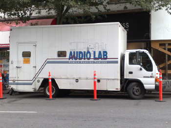
As an interesting aside, my years of copying weak CW tones, has shown itself in other ways as well. Before retirement as a high school tech ed teacher, staff were required to have their hearing checked annually, as part of the medical plan's requirement. Each year the mobile audio lab would roll-up for the tests. I would always make sure to sit perfectly still, with no headphone cord wires brushing against my clothing. The tones varied in frequency and intensity and were often extremely weak, not unlike the weak echoes I was used to copying from the lunar surface. The reaction from the examiner was always the same, every year ... complete astonishment when checking the results and usually a comment that I had the hearing of a teenager! Thankfully my hearing, which I've always been careful to protect, remains exceptionally good, for which I am truly grateful ... so often this is a genetic thing and there is little one can do about controlling hearing-loss as one ages.
I shudder anytime I see a young person with headphones or earbuds firmly in place and with the music volume cranked up to unbelievably high levels. Sadly, many of them will likely pay the price for this later in life as such hammering-away at the delicate auditory mechanism has a cumulative rather than a short-term effect.
So ... the next time you find yourself trying to copy that ultra-weak signal just riding along in the noise, try turning the audio way, way down. Take a deep breath and listen to the tone, not the noise. If you ask me, the best signal filter is still the one between our ears.


