Author Archive
 On the air!
My QRSS beacon is now on the air, running 50mW into my MFJ magnetic loop in the attic. It is showing up very well right now on the grabber of PA0TAB.

I also saw it less strongly on the grabber of I2NDT, but I forgot to grab the image before it faded into QSB.

Reception reports will be most welcome to:
Bricked chip
Last night I received an email from Steve G0XAR to let me know that a replacement chip for the QRSS beacon had been programmed but not posted yet as he had been ill with a bad cold. However my impatience had got the better of me and I started wondering whether I could reprogram the chip myself. Perhaps this was the opportunity I needed to start playing with microcontrollers? The source code was on Hans G0UPL’s website, the development tools were all free. All I would need is a programmer, and I was sure I had seen circuits for microcontroller programmers knocked up from junk box parts on the web.
A bit of searching revealed that simple programmers for the AVR ATtiny13 chip can easily be made, such as this one built by Alan, VK2ZAY, but they require a parallel port, an antique piece of hardware that went out of use around the time Bill Gates made his first billion and is now as obsolete as the USB port will one day surely be.
However I also came across an article that described how to program AVR microcontrollers using a Microchip PICkit2 programmer. A couple of years ago I obtained a PICkit2 because it was being offered in an electronics magazine for just the cost of the postage. Apart from running a couple of demo programs I had never done anything with it. What more of an excuse did I need?
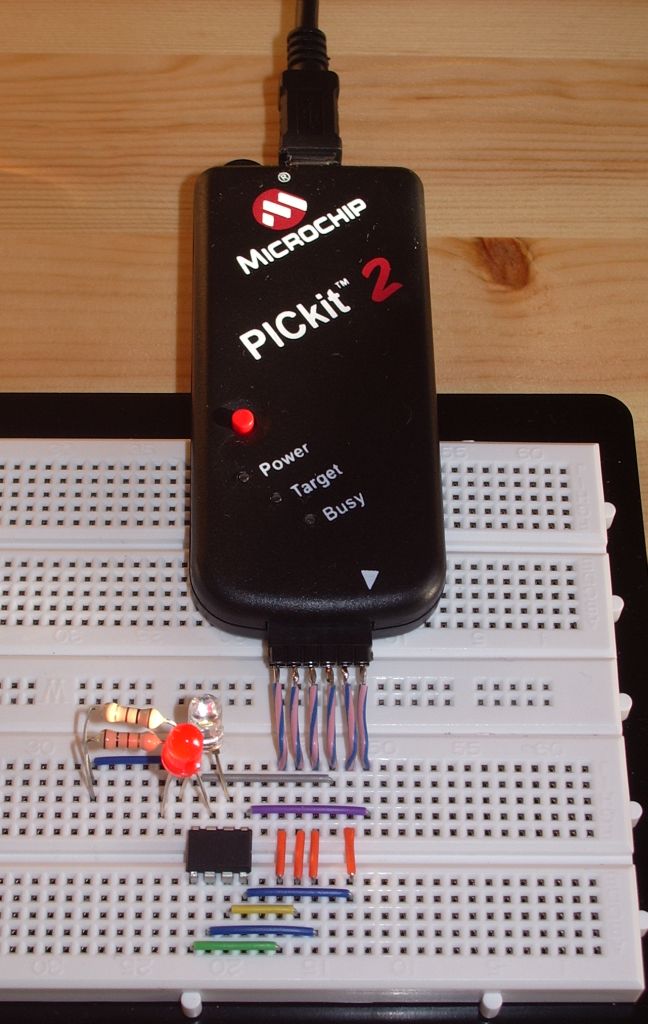
In less than an hour I had downloaded and installed the AVR Studio software, WinAVR which was also needed, PK2AVRISP (the program which makes the PICkit2 look like an AVRISP or STK500 programmer), soldered six short leads to a 6-way header to attach to the PICkit2 and wired up the connections to the chip on my solderless breadboard. I already had a pair of virtual serial ports set up on the shack PC to use with the TrueTTY packet TNC so I was good to go.
PK2AVRISP detected my PICkit2 and I assigned it to one of the pair of virtual serial ports. The QRSS keyer program compiled in a couple of seconds and I was ready to program the chip. I selected the AVRISP programmer on the other end of the virtual serial port pair. The programmer read the signature from the chip and reported it was correct – an encouraging sign. Then I wrote the hex code into the flash memory. The write appeared to work but the verification failed with “WARNING: FLASH byte address 0×0006 is 0xFF (should be 0xCF).”
I searched forums for solutions to this error and tried various suggestions such as reducing the SPI clock speed or trying the STK500 option but I could not get past this error. One person claimed that he had somehow managed to program the chip despite the error so I put it back in the QRSS keyer, but now I just got a steady carrier with no keying at all. Oh dear!
I tried programming the code again this time using the avrdude command line programming software which is included with WinAVR but can’t be run directly from AVR Studio. This appeared to work, no error was displayed when the code was verified, but the chip still did not work when put back in the keyer.
To avoid moving the chip back and forth to test it after each programming attempt I tried programming a simple LED flasher into it so I could test it on the breadboard (hence the LEDs in the photo.) This works fine if I simply ignore the flash verification error. So the chip isn’t bricked. But why the keyer program doesn’t work is a mystery. I assume it should flash the LED on pin 3 in time with the keying, but it doesn’t.
Obviously a new chip will get the QRSS keyer working again but having spent all this time on trying to do it myself I would like to know why I couldn’t. Usually when something doesn’t work it is because I have made a stupid error, but I can’t see what I have done wrong. It’s so frustrating.
QRSS beacon progress
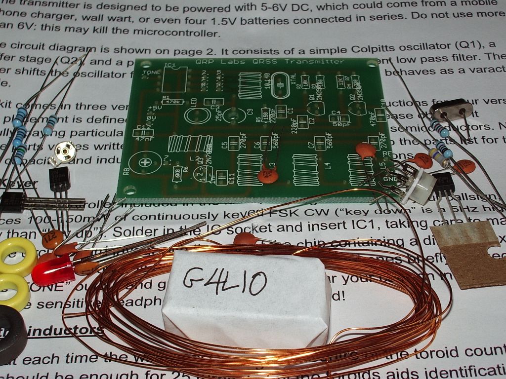
Yesterday I finished building the QRSS beacon kit board. The keyer chip sends the wrong callsign but it that was no reason not to build the kit. It’s a very easy kit to build although there are no fewer than five toroids to wind which is a lot for such a simple project. Some people hate winding toroids though I find them easy to do and can’t see what all the fuss is about.
The only other slight difficulty with the kit is that the potentiometer for setting the output power has leads that are too big for the holes in the PCB. This is mentioned in the instructions, where it is recommended to use component lead offcuts to extend the originals. My junk box was supplemented a few months ago with a Maplin bargain pack of assorted potentiometers and lo and behold it yielded a wirewound trimpot of exactly the right value that perfectly fitted the PCB holes. So I used that instead.
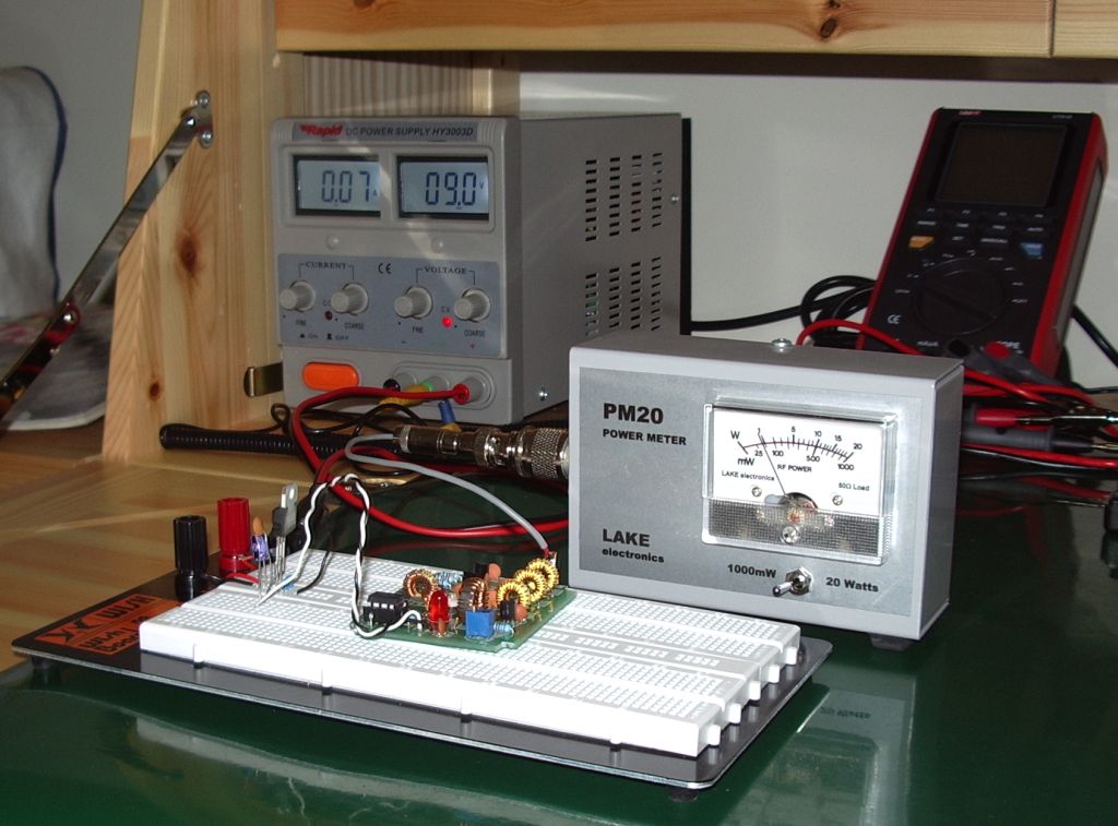
When the board was finished I powered it up using my bench power supply and PM20 QRP absorption wattmeter. In the photo I have breadboarded a regulator from 9V down to 5V as I was toying with the idea of running the beacon from a rechargeable PP3 battery (the board will fit into a case I have which has an integral PP3 battery holder) and wanted to see how much heat the regulator would dissipate.
I found that I could get a maximum of just under 100mW from the beacon with about 120mA current drawn. This is a little less than the specification. The instructions suggest that a bit more than 100mW should be possible, but the shortfall isn’t enough to worry about. For longer battery life I will run the beacon at 50mW which draws a current of around 65mA.
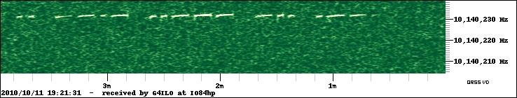
To get the transmitter on frequency and set up the mark/space frequency shift I used my K3 and QRSS VD software. The signal, even on the dummy load of the power meter, was very loud which was helpful getting it into the ball park. I had to disconnect the antenna, switch in the attenuator and back off the RF gain to reduce the signal to a level where I could fine-tune the frequency and see what the signal would look like on the air.
And here it is, sending G4LIO! It’s a bit frustrating not being able to connect it to an antenna and put it on the air because of the wrong callsign. I’ve been promised a new chip and I practically snatched the post out of the hands of the postwoman but it hasn’t come yet. In the meantime I can think about putting the beacon into a nice box. Forget winding toroids, for me that is the hardest and least enjoyable part of any constructional project!
Technology failure
Olga and I went to a dinner party last night and the topic of how we have become slaves to computers came up. When I was a child, the science books promised that technology and automation would make our lives easier so we would work less hours and have more time for leisure. What a joke that seems now. We all work longer hours and the impact of computing and modern communications technology is that people now expect answers instantly instead of when you can get around to it. When I mentioned another promise of the computer age, the paperless office, the entire table fell about laughing.
Kelly, K4UPG writes that he had just spent six hours running updates, fixing the problems the updates created and figuring out how to install the updates that wouldn’t install automatically. His verdict: Computers Do Not Save Time.
The last couple of mornings Acronis Non-stop Backup has displayed a message that it was not running. Kelly’s post made me wonder if this was caused by a recent Windows update. I decided to do a System Restore back to last Monday, before most of the updates occurred, and lo and behold Non-Stop Backup is running again. I don’t have the inclination to spend six hours installing updates individually to find which one caused the problem, nor to ferret through forums searching for a solution, so automatic updates have been switched off for the time being. Having a working backup is more important than receiving fixes to problems I haven’t experienced and probably never will.
The trouble with computers is you have to spend too much time being your own support technician, time you should be spending working, playing radio or whatever the computer is supposed to be helping you with. Once upon a time computers were simple, reliable and never needed updating. What was the name of the operating system they ran? Ah yes, MS-DOS.
Grab me a callsign
While I wait for a correctly programmed chip for my QRSS keyer kit I thought I would investigate the receive side of QRSS beaconing. It’s no good transmitting if nobody receives, and unlike WSPR every transmitter isn’t automatically a receiver during its off periods. This is a mode where you need to give as well as take, to receive in order to be heard, otherwise you can’t complain if no-one tells you that they heard you.
QRSS signals are decoded visually using a spectrograph, a waterfall display similar to that found in digital mode software. However, you can’t use a digimode software waterfall for two reasons: it moves too quickly – to capture a full callsign in QRSS you need to be able to see at least a couple of minutes worth of transmission – and it scrolls down vertically so trying to read calls would give you a crick in your neck!
Fortunately there are programs that have been specially written for just this application – and they are free so there is nothing to stop you trying them. The most popular program for Windows appears to be Argo. However there is alternative called QRSS VD by Scott Harden (the odd choice of name becomes clear when you realized that Scott’s call is AJ4VD.) QRSS VD has one problem: it is a CPU hog. On my fairly modern shack PC it runs at about 50% CPU utilization. For that reason, you might have no alternative but to use Argo. But if you can run QRSS VD it has some nice features that add to the enjoyment of this aspect of the hobby.
QRSS VD includes three programs: a Spectrograph, a Viewer and a Grabber. The QRSS VD Grabber automatically captures the live waterfall and creates images suitable for uploading to a website so others can see whether you are receiving their signals. It doesn’t have any way of automatically uploading the images to the web server, though. It’s really for people who want to run an online grabber, which is only worth doing if you are going to run it regularly. I don’t have enough radios and antennas to do that so I probably won’t investigate this feature further.
QRSS VD Spectrograph is the program that displays in real-time what you are receiving. It has no obvious user interface – you have to right-click the window and then you will get a menu of options. One option lets you select the sound card that is connected to your radio. Another is for setting the frequency. The main settings option determines the size of the window and the maximum and minimum frequencies that are displayed.
There is also an option to save these settings. If you don’t, you will have to set them all over again the next time you start the program. Finally there is the Resume option which you must click to start the spectrum display working.
Most QRSS activity takes place on the 30m band, in the first 100Hz above 10.140 MHz. This is just below the 200Hz used by WSPR, which is itself just below the region where PSK31 operation takes place.
To start receiving QRSS, set your receiver to USB mode and tune it to 10.139.000. If your rig has a DATA mode that is USB you can use that. Don’t be tempted to use the CW mode – most rigs add an offset to the displayed frequency so it shows the frequency in the centre of the CW filter passband, and some rigs use LSB for CW, so finding the right spot gets confusing.
Select the sound card in QRSS VD, then set up the settings dialog. The window width in pixels can be whatever suits your screen size. The bandpass low and high settings define the height of the window, the minimum and maximum audio frequencies displayed on the spectrograph. With the radio on 10.139.000 USB, signals in the QRSS sub-band will be heard at audio frequencies of 1000 to 1100Hz. I set the low and high values to 950 and 1150Hz respectively to give a 50Hz margin on either side. (Note: if you aren’t sure of your receiver’s accurate calibration you might want to choose a wider margin initially because you could miss the QRSS band entirely of it is more than 100Hz out.) The other values on this dialog are all defaults.
[If you are interested in receiving WSPR as well, you could tune the radio to 10.138.700 and enter low and high values of 1250 and 1450Hz. Then you could run WSPR and QRSS VD on 30m simultaneously.]
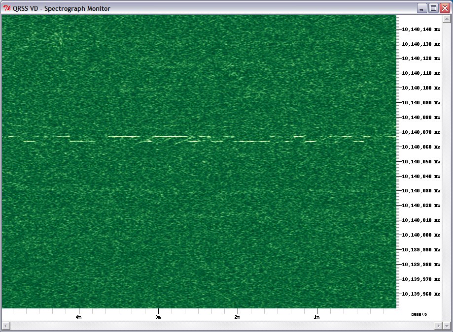
Right-click the spectrograph window, click Resume and the screen should start scrolling to the left and filling with received signals. Conditions are pretty poor at the moment so there isn’t much to see on the screenshot I made, but when I first tried this program I immediately received a trace of a signal from Steve, G0XAR who coincidentally is the producer, together with Hans G0UPL, of the QRSS beacon kit I just bought. I don’t know if he was using one of these kits but it was producing a heck of a signal. (Ignore the frequency shown, this was received using my K2 whose calibration is considerably out.)
What’s nice about the QRSS VD software is that you don’t have to watch the output in real time to capture signals and it is simple to produce nicely formatted records of signals received like the one above. Every few minutes the spectrograph dumps a bitmap file in the program’s Output folder. When you want to see what you caught you start up the QRSS VD Viewer, select a group of bitmaps to view and it will stitch them into a seamless time continuum. You can then scroll through from start to finish looking for the traces of QRSS signals.
When you find one, you can capture a region of the spectrograph by clicking to specify the top left and bottom right of the desired area. You can even specify a custom caption. The selected area is then copied to the Windows clipboard and pasted into your default bitmap viewer ready for you to save in a format of your choosing (for example, as a JPG file.)
Why would you want to do this? As I mentioned at the beginning, there is no way of finding out how far your signals got (apart from a handful of online grabbers) unless someone sends you a signal report, so if you receive someone’s beacon you should send them a report too. The only way to do this is to look up their email address at qrz.com and send them an email. A picture is worth a thousand words, so it’s nice to be able to send a screen grab of their actual signal as an attachment to the email.
If my initial experience is anything to go by, this personalized way of sending signal reports makes for a very friendly aspect to the hobby. I sent this capture (above) of a beacon from IQ2DP with an emailed report. This morning I received a nice reply from Teo I2RIT thanking me for the report and telling me all about the beacon, which is made from junk box parts and runs well under 100mW into a ground plane made of scrap aluminium tubing. He also sent a link to an article about it. The article is in Italian but here is a translation. If you’ve read this far then you will probably find it interesting. Yet another facet to our amazingly varied radio hobby.
Getting old
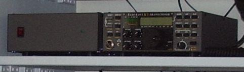
After breakfast this morning I went up to the shack as usual. I switched on the computer, switched on the main power supply and switched on the Kenwood TM-D710. When Windows came up I started my VHF instance of APRSIS32 for my local APRS gateway. Then I switched on my K2 to start the HF gateway. The LCD showed the usual “Elecraft” but then the segments went crazy and the radio emitted a noise that can best be described as an endless fart.
I switched off. Then I realized that I had forgotten to switch on the K2’s power supply. I switched it on, then I switched the radio on again and this time it started up normally. Phew! Then my fuddled brain worked out that this must mean the K2’s internal SLA battery has finally given up the ghost.
I built my K2 in 1999. Originally only the basic radio was available as a CW-only kit. Other options were soon added including the KSB2 module for SSB, the internal ATU and an internal battery pack. I added these options as soon as they were available, which must have been around the end of 1999 or early 2000, so the battery must be around ten years old.
As it happened I have rarely used my K2 portable so I have made little use of the battery pack. I used the radio in the field once earlier this year. The previous occasion on which I ran the K2 from the battery was during the floods a year ago when the power went off for several hours and I was able to experience what the bands were like without all the local QRN. Ten years is a very good life for an SLA battery and I wondered when it would fail, but I hated to throw it out while it was still doing its job. It seems that time had finally come.
I removed the top cover from the K2, disconnected the cables and lifted it off. Then I undid the screws securing the aluminium bracket that holds the battery in place. I noticed a small patch of corrosion in the area adjacent to one of the terminals, and when I removed the battery I noticed a drop of liquid in the same place. The battery had started to leak. I had got to it just in time. If my fuzzy-headedness hadn’t caused me to turn on the K2 without the power supply I might never have noticed the problem until it was too late and some of this electrolyte had dripped into the radio itself!
I’m not sure whether to replace the battery pack or not. In the meantime I thought I would put the battery bracket back and tape the battery cables to it, then put the top back on the K2 and get my HF gateway back on the air.
But it isn’t just the K2 that is getting old. I am, too, and I hate it. I’ve never had particularly good co-ordination but it seems to be getting worse. I can’t use a Morse paddle now and I can’t send faster than 12wpm with a straight key. Sometimes I have days where I’m even more clumsy than usual and my hands shake too much to do any constructional work. In that state it’s impossible to hold nuts and washers in hard to access positions while you turn a screw from the other side. I’m having one of those days today and I found that I couldn’t put the battery cover back. So I’ve put the K2 in a drawer until a day when I’m feeling sharper. Hopefully I’ll be able to give it a realignment at the same time, something else it probably needs after ten years. Until that time I will be off the air on HF APRS.
QRSS Keyer
I have operated most of the reverse beacon and weak signal modes but one that I have never tried is QRSS. “QRS” is the Morse Q code for “send slowly” so QRSS means send very slowly indeed. QRSS beacons send your call using very, very slow Morse, which listeners receive using a “grabber”, which is a slow moving waterfall display. If you’re lucky, they will email you a reception report, but you can also look for your signal yourself on one of the various online grabbers.
One day I planned to build my own QRSS beacon. When I found out that Hans Summers G0UPL had produced a QRSS beacon kit I was disappointed to learn that all the kits had been sold at the US Dayton hamfest. However I recently discovered that he had made a new batch of kits and not wanting to wait and find out they were all sold at the G-QRP Convention I ordered one at the weekend. The order process was extremely professional (amateur components suppliers who expect you to email your order and credit card details please note) and the kit arrived this morning.
I opened the envelope and was very impressed to find that the package included a printed copy of the instructions as I had expected to have to print them myself from the website. The PCB is of very high quality. But as I tipped the parts on to the workbench my heart immediately sank.
Because the microcontroller chip which keys the transmitter and has been preprogrammed with my callsign was wrapped in a slip of paper on which was written G4LIO, a transposition of my call that often afflicts people on the air as well – I don’t know why. The incorrect call was also written on the jiffy bag the kit came in. I checked the emailed copy of the order and the mistake was not mine.
After an exchange of emails with Hans I installed the chip in its socket, applied power and connected an earpiece to pin 2 which produces an audio tone to verify whether the chip had been programmed incorrectly. It sent G4LIO. 🙁 Why is it always me that gets the kits with the missing or faulty parts?


