 |
 QRSS beacon progress
Yesterday I finished building the QRSS beacon kit board. The keyer chip sends the wrong callsign but it that was no reason not to build the kit. It’s a very easy kit to build although there are no fewer than five toroids to wind which is a lot for such a simple project. Some people hate winding toroids though I find them easy to do and can’t see what all the fuss is about.
The only other slight difficulty with the kit is that the potentiometer for setting the output power has leads that are too big for the holes in the PCB. This is mentioned in the instructions, where it is recommended to use component lead offcuts to extend the originals. My junk box was supplemented a few months ago with a Maplin bargain pack of assorted potentiometers and lo and behold it yielded a wirewound trimpot of exactly the right value that perfectly fitted the PCB holes. So I used that instead.
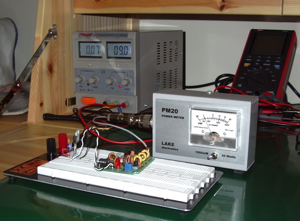
When the board was finished I powered it up using my bench power supply and PM20 QRP absorption wattmeter. In the photo I have breadboarded a regulator from 9V down to 5V as I was toying with the idea of running the beacon from a rechargeable PP3 battery (the board will fit into a case I have which has an integral PP3 battery holder) and wanted to see how much heat the regulator would dissipate.
I found that I could get a maximum of just under 100mW from the beacon with about 120mA current drawn. This is a little less than the specification. The instructions suggest that a bit more than 100mW should be possible, but the shortfall isn’t enough to worry about. For longer battery life I will run the beacon at 50mW which draws a current of around 65mA.
To get the transmitter on frequency and set up the mark/space frequency shift I used my K3 and QRSS VD software. The signal, even on the dummy load of the power meter, was very loud which was helpful getting it into the ball park. I had to disconnect the antenna, switch in the attenuator and back off the RF gain to reduce the signal to a level where I could fine-tune the frequency and see what the signal would look like on the air.
And here it is, sending G4LIO! It’s a bit frustrating not being able to connect it to an antenna and put it on the air because of the wrong callsign. I’ve been promised a new chip and I practically snatched the post out of the hands of the postwoman but it hasn’t come yet. In the meantime I can think about putting the beacon into a nice box. Forget winding toroids, for me that is the hardest and least enjoyable part of any constructional project!
 Ham Radio Deluxe |
 W5SWL Electronics |
 Ham Radio Prep |
 KB3IFH QSL Cards  Hip Ham Shirts  HamRadioAuctions HamRadioAuctions Reliance Antennas Reliance Antennas Enigma Shop Enigma Shop |  morseDX  Ni4L Antennas  R&L Electronics R&L Electronics antennas.us antennas.us QRV QRV |
- Matt W1MST, Managing Editor
