Author Archive
 Foul!
Foul!
Following a tip from the VX-8R Yahoo group I ordered a high capacity 2000mAh FNB-102Li battery for my VX-8GR from a dealer in Spain that was selling them for EUR 28.50. The website couldn’t calculate shipping to the UK so I received an email asking me to order two connectors the cost of which equalled the cost of the shipping, making a total of EUR 36.80 – still much less than the price of the Yaesu product even when ordered from Hong Kong. After this was sorted out the battery was with me five days later.
My pleasure at the speed of the shipping soon turned to dismay. Yaesu chose to make the VX-8 belt clip attach to the battery pack. I don’t know whether the accessory batteries bought from Yaesu come with a belt clip to attach to them but this one doesn’t, so if I want to interchange this battery with the one that came with the radio one of them will have to be used without a belt clip.
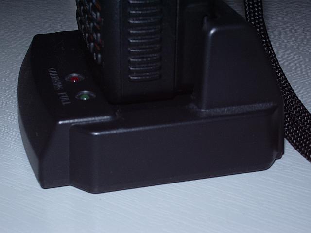
But worse was to come. The battery will not charge in the drop-in charger while it is attached to the radio! The charger has a platform which, as owners will know, is deeper than the radio with the stock battery – presumably to accommodate the thicker higher capacity version. But with this battery attached, the front of the radio fouls the lip at the front of the charger where the status LEDS are, preventing it from dropping the last tenth of an inch necessary for the battery contacts to make contact with those on the charger.
Is this a general problem with the FNB-102Li and the VX-8GR (in other words, is the GR thicker than the DR and my charger doesn’t allow for this?) or is it just this third-party battery that is thicker than the one from Yaesu and causing the problem? I’m having to take the battery off the radio to charge it, but that rather spoils the convenience of having the drop-in charger.
Connector conundrum
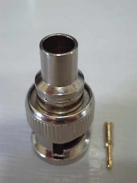
What is one supposed to do with the BNC connector pictured right?
I ordered 5x Crimp On BNC Plugs from eBay, expecting to get plugs with a narrow body and separate small piece of tube that you use to crimp the braid of the cable to the body of the plug. What I actually got was these, which I already had a couple of and didn’t know how to use. The only way I can see that you could use these is to crimp the large diameter barrel on to the braid itself, but with nothing but the nylon insulation beneath it you are not going to get a good contact. I think they are useless, though I did make a QRPP dummy load from one of the originals as two 1/4W 100 ohm resistors in parallel just fit inside the body of the plug and you can solder the ground ends to the outer.
I guess soldering the braid is the answer, but that isn’t what I bought crimp on plugs for and it isn’t going to make a very neat job.
K144XV comments
The K144XV eventually turned up late on Thursday afternoon. After the board modifications had been performed, installing the transverter module was easy following Elecraft’s exemplary instructions. I had to remove the KIO3 module in order to remove the KXV3 transverter module and replace it with the KXV3A, which has a couple of additional connectors for the internal transverter, then replace the KIO3. I also had to replace the side panel of the K3 with one that has some extra holes for securing the transverter. The stiffener that runs across the top of the case is also replaced by one with a cutout where it passes over the K144XV.
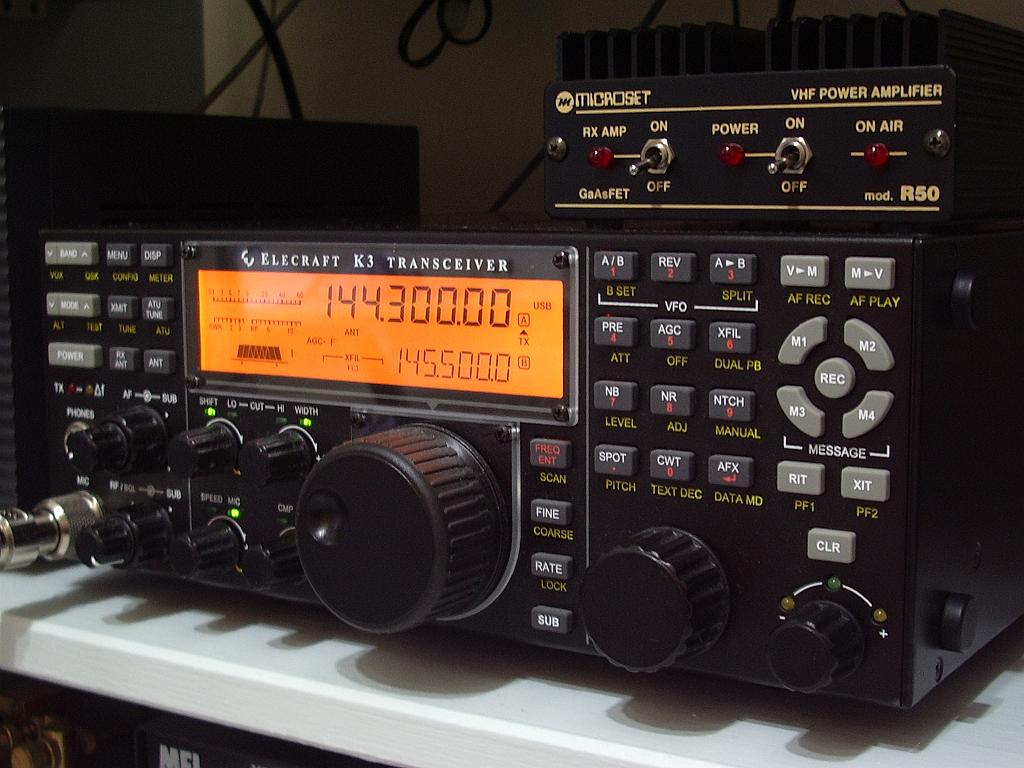
Due to the lateness of the hour I was a bit tired and also focussed on getting the job finished so the shack could be restored to normality so I never even thought about taking some pictures. The module comes as a complete screened box not a bare board as shown in some of the pictures on the Elecraft website. It is quite a little beauty and the way it all fits into the K3 is a work of art.
Although described as a 10W module the instruction manual states that you should get at least 9W with 1.0mW input to the transverter. I actually got about 11W so the power output comfortably exceeded spec. At my noisy location I can’t make any meaningful observation about sensitivity – any half decent 2m radio will be sensitive enough. But I did notice that S meter readings are extremely low. I see no movement at all on a clear frequency despite the noisy location and a repeater that lights all the signal strength bars of my TM-D710 registered just S4 on the K3. I never take any notice of S meters anyway so I’m not unduly bothered. The amplifier “brick” I will use with this has its own built-in preamp which will boost S meter readings if I want.
The 2m amplifier I have was designed to be driven by an FT-817 so it only requires an input of 5W. I found that I needed to reduce the drive to the transverter to a mere 0.15mW to achieve this level of output. I don’t know how accurate the low level output power settings of the K3 are but the relationship between 28MHz drive in and power out is definitely not linear. However the signal on SSB sounded pretty clean when monitored on the FT-817.
The calibration of the transverter local oscillator is done using software, not by trying to tweak a trimmer capacitor by a fraction of a hair’s breadth, which is a blessing. There are two local oscillators in the transverter to provide coverage of the full US 2m band (144 – 148MHz) using the same 28MHz – 30MHz range (interestingly the top 2MHz is not disabled in European rigs.) The transverter module is calibrated at the factory and you have to enter the calibration values into the K3 using the configuration menu. I checked the result using my FC-1 frequency counter and also my FT-817 and it appeared to be accurate to within 100Hz which is about as good as I can get. Later I listened on the GB3VHF beacon frequency and waited for the beacon to come out of the noise. I believe this beacon’s frequency is GPS locked. The frequency appeared to be out by 120Hz so I was able to adjust the calibration value and get it spot on.
The signal to noise ratio on a weak FM signal is definitely better on the K3 than with my other 2m rigs but I don’t see the K144XV as being the solution for people whose primary interest 2m FM. One reason is that a 2m mobile rig is cheaper and allows you to monitor and work 2m FM at the same time as using your K3 for something else. Another is that the K3 doesn’t really handle channelized operation very well. The memory system has improved considerably since the early days but using the VFO to scan through memories rather than a click stop rotary control doesn’t work for me, especially due to the laggy response of the K3 to the turning of the knob.
But I think the K144XV is an excellent option if you want to work 2m DX. The receiver sounds quiet and clean and having all the QRM fighting and weak signal detecting tools of the K3 available on 144MHz is a real bonus. Now I just have to wait for some 2m SSB activity to try it out!
K3 mod fun
Today I have been waiting for Parcel Farce to deliver a K144XV internal 2m transverter board for my K3. I hate doing modifications to the K3. First there is the hassle of disconnecting all the cables that are plugged in the back. I have to disconnect practically everything in the shack in order to remove the shelf above the K3 so I can see what I am doing.
I also dislike making modifications to the K3 itself. It makes me nervous thinking of the cost and expense if I mess something up and it doesn’t work. I’m starting to think that if I want to stick with the K3 it would be better to sell this 3 year old one and get a new current model. Because there have been so many modifications now since my serial number 222 was produced. I haven’t done many of the mods because I don’t think they make a worthwhile difference or because they involve obtaining an exchange board from Elecraft and the cost of doing this including shipping, VAT and tax collection fee is more than it is worth. But the internal 2m module seemed in the end to be the best solution for providing a capability for 144MHz SSB, even though it involved exchanging my KXV3 transverter interface board for a KXV3A.
In order to install the K144XV it is necessary on older K3s like mine to mount a socket on the main board to provide power. This involves removing the bottom panel of the rig. I thought that while I was doing that I would do another mod to increase the IF output which would be necessary should I ever want to use a P3 panadapter with the rig. The mod involves changing one resistor, oddly specified at 13K. An enquiry on the Elecraft reflector about whether the value was that critical resulted in the kind offer from Ian GM3SEK to send me a couple of SMT resistors so I could do the mod. Without Ian’s help I would have had to leave the mod until I got a P3 and Elecraft sent the replacement part because SMT resistors aren’t something you can buy from Maplin in quantities of one or two off.
I had shied away from doing mods involving SMT parts before but I found that it wasn’t too hard. However I did need to use a high magnification lens in my head-mounted visor. I was initially alarmed to see that the resistor I had to change wasn’t one of the fairly big SMT resistors that are normally used in kits using these type of parts, it was a really tiny one. I used two soldering irons, one at each side, and then flicked the resistor off. After cleaning the pads with a bit of solder wick I then took one of the replacements using a trimming tool with a bit of Blu-Tack on the end and held it in place while I took a blob of solder on the end of my smallest bit and tacked one side of the resistor into place. Then I did the same to the other side. Job done.
Although the high magnification makes it possible to see the tiny parts, it can’t do anything about shaky hands. My hands seemed fairly steady this morning but it is a different picture through a high magnification lens and you don’t need to move far to shift the component out of its precise spot, which of course I did. I decided this is no job to be fussy about. The resistor was slightly skew-whiff, but it was attached to the board and my ohm meter said everything was OK. Perhaps I could get a job working for MFJ. 🙂
The package from Elecraft still hadn’t arrived so I decided to pull up the instructions for installing the K144XV from Elecraft’s website to see what was involved. As I mentioned, I needed to install a terminal to provide 12V to the transverter module. This is a bit of a kludge as the K144XV wasn’t even a planned option at the time my K3 was made so there isn’t a proper place for this terminal. You have to solder it in using a “via” that wasn’t actually designed for this use. Unfortunately that via had been used by one of the leads of a wire-ended capacitor used in another mod to improve the low frequency audio response.
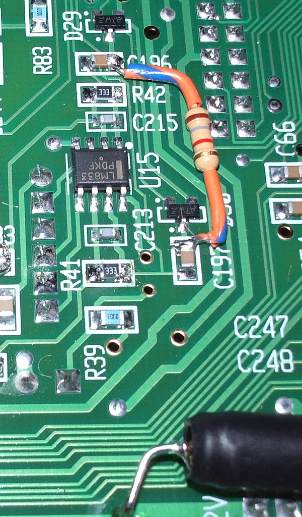
The instructions mention this possibility and suggest an alternative via. However that via was obscured by the components used to perform yet another mod, this time the hardware AGC modification. Lacking the confidence to remove and replace SMT parts I had used wire ended components to do this mod. There was no alternative but to remove the mod and do the SMT version. Elecraft had provided both types of components and fortunately I hadn’t lost the SMT ones. However they had not provided any spares and I was conscious that one false move sending a resistor pinging off to oblivion would result in a K3 I would be unable to use until I could find a replacement. That didn’t help the shaking hands one bit!
Fortunately it all went well, with the results shown in the picture. (The resistors I had to replace are the ones marked 333.) So that’s done. But still no transverter. Where the hell are you, Parcel Farce?
Unwanted
Charles M0OXO laments the fact that England is 334th in the list of the most wanted 338 DXCC entities, in other words the fifth least wanted. Isn’t it a sad waste of a hobby not to mention the vast sums of money people spend on equipment and antennas if the main interest in making a contact is just to be able to tick off a new country? I guess that’s why I find DXing and DX blogs boring. I’d rather read about what people are building, new things that they are experimenting with or how far (even if it isn’t all that far) someone manages to work with a peanut whistle.
Automatic Voice Relay System
One of the reasons why I have not been an enthusiast of the D-Star system is that it creates a separate class of activity incompatible with existing voice modes just for the dubious benefit (from an amateur point of view) of using digital voice instead of analogue. Using EchoLink, IRLP and APRS we already have a global network that allows one ham to contact another anywhere in the world using ham radio, one that does not require anyone to purchase expensive new equipment from Icom or anyone else. What we have not done is put it together in a way that makes it work seamlessly as a coherent network.
Automatic Voice Relay System (AVRS) is an idea by Bob Bruninga, WB4APR, the inventor of APRS, first published in 2000, to create a system that allows users of EchoLink, IRLP and even D-Star to inter-communicate. APRS provides the location and identification information for the analogue FM EchoLink and IRLP users, something that is already built in to the D-Star system. As is often the case, those who have the great ideas don’t always have the skills needed to bring them to fruition, so AVRS remained little more than an idea for ten years.
Now, apparently, a developer has been found who is able and willing to write the software that will enable AVRS version 2 to come into being. You can read more about AVRS here. For seamless one-button operation you will need one of the new generation of APRS-capable radios (Kenwood TM-D710, TH-D72 or Yaesu FTM-350) that are able to QSY to a frequency contained in an APRS packet. Some will argue that if you are going to buy one of those, why not buy a D-Star radio instead? But AVRS capability, being based on APRS, can easily and inexpensively be added to any analogue FM radio. AVRS will not leave analogue FM users out in the cold because their local repeater converted to D-Star, as has happened in some parts of Britain.
One of the interesting aspects of AVRS version 2 is the development of A-Star repeaters. These are analogue FM repeaters with a D-Star gateway that use the D-Star network to link them together. Callsign and location (if known) information is transmitted as a 0.3sec APRS packet burst at the end of each over. A-Star users will appear to D-Star users just like other D-Star users and can easily intercommunicate. A-Star users can initiate a contact with another A-Star or D-Star user just by sending an APRS message starting with A*. A-Star users don’t even need to be monitoring a repeater in order to be contactable: they will receive the message as an ordinary APRS message and can QSY to the repeater (with one button press if using one of the radios mentioned above) using the information contained in it.
AVRS looks like a great idea with the potential to bring digital and analogue voice users together. It might even erode some of the analogue vs D-Star conflict.
A matter of timing
I’m finding it hard to love the new Kenwood TH-D72. Despite the fact that it has a more sensitive GPS, a proper TNC that you can interface to computer APRS or packet software and is firmware upgradeable, I’m steadily coming round to the opinion that the VX-8GR is the better performing, more usable radio.
Things I don’t like about the TH-D72 is that it is bigger and heavier, has a screen that gives far less information at a glance than the corresponding screens on the Yaesu and has poorer ergonomics. I have also been harbouring a suspicion that its packet modem was less sensitive. Today I think I discovered the reason.
I recently built a Fox Delta weather station that outputs AFSK packet directly into a radio. I noticed that although my Kenwood TM-D710 and my VX-8GR decode it’s S9+ packet bursts the TH-D72 didn’t. I thought it might just be a case of adjusting the deviation but I tried the weather station on two different radios adjusting the audio level from nothing to definitely clipping and could not find a setting at which the D72 would decode anything.
Recently I set up a low power APRS repeater in the shack. It is a sound card TNC (TrueTTY) driving a low power UHF radio (the FT-817ND) running into a dummy load, which is connected to the aprsg gateway software. This gates everything that is going on in APRS within a specified radius to UHF so that I can monitor activity and reply to messages using an APRS HT anywhere I am in the house. This has been working fine with the VX-8GR but last night I forgot to switch it off and the battery was dead so I tried monitoring using the TH-D72 instead. Nothing was copied!
Again I tried an entire range of audio levels into the radio but while the VX-8GR and the TH-D710 both decoded the packets over a wide range of settings the D72 didn’t decode anything. I was using TrueTTY into my USBlink home-made VOX-based digital interface. I wanted to try different software (AGWPE) and a different sound card but Windows got confused having different USB sound devices connected to it and it is also a dog at handling serial ports. I have real serial ports occupying COM2 to COM5, a pair of virtual ports mapped between COM8 and COM9, and other USB serial devices I have used in the past have been assigned to COM1,6 and 7. AGWPE can only use COM1 to COM9 and trying to change the USB serial device to use one of the three currently unused ports in this range resulted either in Windows complaining that the port was in use even though it didn’t show in Device Manager or the application saying that the port did not exist even though it did show in Device Manager. Eventually things seemed so screwed that I restored back to this morning and gave up.
Having restored the system and checked that everything worked again one more idea occurred to me. TrueTTY allows you to specify the exact sample rate used by the sound card, to compensate for timing errors. Instead of 11025Hz I tried 11000Hz and while the D710 and the VX-8 still decoded the packets the D72 still didn’t. I then tried 11050Hz and lo and behold, the D72 started decoding!
It’s impossible to make a suggestion that there is something wrong with a radio in the owners’ groups on Yahoo as so many people can’t bear to consider the fact that something they bought is anything less than perfect and will come up with any alternative explanation they can think of. So I’m sure that the problem I have described will be blamed on the AFSK modulation being slightly off-frequency which, of course, it is.
However in the real world a radio will be used to receive transmissions from people whose modulation is off and don’t know it or may not even have any way of adjusting it. A modem that is more tolerant of these deviations from the precisely correct will decode more signals than one that expects the modulation to be spot on and in that respect the VX-8GR is by far the most easy-going and most sensitive of all the APRS radios.
It’s just frustrating to hear braaaps and not see them decoded, so I think the Yaesu is going to be the one of these two APRS hand-helds that I hang on to.


