Author Archive
 60m WSPR using 500mW QRP
I have been beaconing WSPR using 500mW all day today. The KAT3 didn’t want to repeat its trick of matching my multi-band dipole so the best SWR I could manage was about 1.8:1. I don’t know how much of the 500mW ended up warming up the ATU or the coaxial feeder.
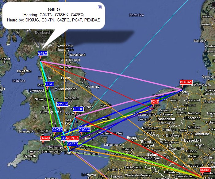
This is a shot of the WSPR propagation map taken just before 1800z today. As you can see, the 500mW is getting out pretty well. I think I have been received by all the G stations that have been monitoring at some time during the day, and a few others. And it was nice to see fellow bloggers Paul PC4T and Bas PE4BAS monitoring even though they can’t transmit on 60m, and better still spotting me!
Just after I posted this, my 500mW was also spotted by LA3JJ!
First emissions on 60m
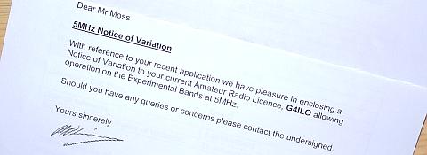
On looking through the mail at lunch time I saw that I had received a letter from Ofcom. My NoV permitting me to operate on the 60m experimental band had arrived!
Until now I hadn’t been bothered about operating on 60m because I couldn’t see how I could possibly find room for an antenna for that band. However a couple of weeks ago I heard someone activating a SOTA summit in the Lake District on 60m and was frustrated that I could not reply to them. So I decided to put in an application for permission to operate and here I am.
I don’t have an antenna that is resonant on 60m so I tried tuning up my multiband dipole using the K3 auto ATU. After a lot of persuasion it managed to find an acceptable match on the higher frequency channels but it gave up on the lower ones. So I should be able to manage some activity on the new band.
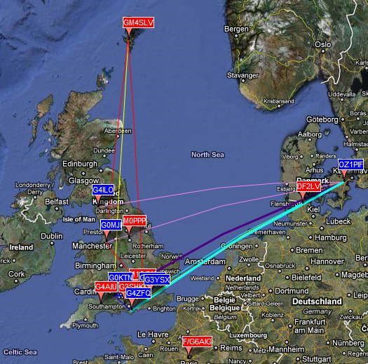
Fortunately, the channel allocated for beacon and WSPR use is one of the ones I was able to match. And today just happened to be a 60m WSPR activity day. So I fired up the WSPR software and beaconed on 60m using 2 watts, increasing to 5 watts in the evening when propagation went long and most of the traces faded out. The 5 watts did me no good at at all, but my 2 watt signal was heard by 7 different G stations all around 400km distance from me plus F/G6AIG at 760km. I received 6 different G stations including G4ZFQ at 458km running 20mW, plus OZ1PIF (my best DX at 984km) and LA3JJ.
Tomorrow is QRP day on 60m when everyone is supposed to run 500mW or less. I have not decided yet how little power I will run but I will be WSPRing on 60m all day. Hopefully there will be a few more people who manage to spot me.
Icom IC-910H Transceiver for sale

I have an Icom IC-910H 144MHz/432MHz multimode transceiver for sale. I will only ship to the UK (or certain other European countries if the buyer agrees to the cost of an insured courier.) More details are on the Equipment for sale page of my website.
Round the back way

Back in the early QRP days of Elecraft, there were some K2 owners who were such CW diehards they were uncomfortable with having a radio that possessed a microphone socket. One or two of them described to the Elecraft email reflector how they had blanked off the offending socket. Despite the evidence in the picture on the right, I have not joined this fraternity. I have simply started using the rear microphone and PTT connector on my K3. I have thought for some time that the front panel connector is an accident waiting to happen, and I finally decided to make the move before it did. (And before anyone comments about the dust in the photo let me just say that one of the few benefits of deteriorating eyesight as you get older is that you don’t notice it!)
Front panel microphone sockets are pretty much the norm in ham radios. However in most radios they are secured directly to the metal front panel or, in the case of radios with a plastic fascia to the metal chassis behind it, using a locking nut which tightens the chassis against the ring cast into the socket so that it is rock solid. You could tug at the microphone cable all you want or bash the connector with a hammer and you would be unlikely to cause any damage to the radio itself.
In the K3, the microphone connector comes soldered to the front panel board. There is no possibility of securing it to the metal front panel. The ring that would normally sit on the outside of the mounting hole actually slips through the hole in the front panel so all the rigidity is provided by the PCB. The front panel hole limits movement up and down or side to side to a certain extent. But it does not provide any protection from movements fore and aft. I wonder about the effects of constant small side to side movements on the soldered joints connecting the pins to the board. And I feel sure that if I accidentally leant on the microphone plug, supporting my weight as I tried to make some connection round the back, I could damage the front panel PCB by snapping the microphone socket right off.
As the outer body of the microphone connector is not physically attached to the radio itself it is not electrically grounded. Whilst installing the K144XV transverter board I noticed that grounding is provided by a piece of bare wire that loops round the threaded part of the connector and is soldered to the front panel board. This may have been a modification that I did myself when I assembed my K3 three years ago. What this wire loop does not do is prevent the outer metal part of the microphone connector from turning relative to the insulated centre bearing the 8 pins that are soldered to the PCB.
Because of the perceived risk of damaging the front panel board by accidentally putting my weight on the microphone plug I have been in the habit of disconnecting the microphone whenever I need to lean over the K3 to grope round the back. So the microphone connector has been on and off rather a lot. Recently I observed a tendency for nothing to happen when I pressed the PTT on my desk mic after reconnection. It then became apparent that the outer metal part of the plug has become slightly loose and can be twisted several degrees relative to the centre. I’m pretty sure this is due to the plug body not being secured to the chassis of the radio so there is nothing to take the strain of tightening and untightening the microphone plug. Hence my decision to give up using the front panel socket and move round to the back before the problem got any worse.
My shack is very cramped so I had shortened the cable on my Heil desk mic to eliminate unnecessary length when plugged in to the front of the K3. Consequently it would not reach round to the back. Rather than rewire the microphone I decided to make an extension cable using a line 8-pin socket, retaining the option of using the front connector if I want. I purchased the line connector quite inexpensively from an eBay seller (where else?)
These connectors are much easier to work with than the mini-DIN connectors I have recently been using rather a lot. The pin numbers are clearly visible, but it’s a good job I checked: in the connector I had the pins had been installed in the metal socket offset by one pin position so pin 1 was labelled pin 7 etc! This could easily have been confusing and so my brain cells got a bit more exercise than expected making sure I got the connections right.
I changed the microphone configuration in the menu to use the rear mic socket and so my microphone is now plugged in round the back. It would be interesting to know whether any other K3 users have had problems with this front panel socket. Once, I would have posted about it on the Elecraft email reflector, but that would only result in several replies from kool-aid drinkers saying that it hasn’t happened to them so it must be my fault.
EchoLink node
A week or so ago my application to operate a part time attended EchoLink node on the 2m band was granted. I didn’t receive any notification of this, I just happened to check the relevant page of the RSGB Data Communications Committee website and noticed that my entry had turned black and an expiry date had been added.
G4ILO-L is EchoLink node number 3098 and operates on 145.2125MHz with a CTCSS Tone of 77.0Hz. As stated the authorization only allows the node to operate when I am on the premises. It uses the non-APRS side of my Kenwood TM-D710 so in practise it will also only operate when I don’t want to operate on 2 metres myself. Therefore it is more likely to be on during the evening UK time than during the day.
The license only allows me to use 5W ERP. Due to my location in the RF black hole of Cockermouth the range will only be a few miles so the number of stations able to access it can probably be counted on the fingers of one hand. Most of the time I will be monitoring the node myself on one of my handhelds so if you call me after connecting there is a good chance I will reply.
I do intend to post a page on my website explaining to other stations in the area how to use it if they want to, but at the moment the number of things to do exceed the available time.
I have developed a script to post the status of the node to the APRS network so an easy way to see whether my node is running or not would be to look up EL-3098 at aprs.fi.
WSPRing on 80
A blog post by Roger, G3XBM, about how far he was able to be received running 5mW of WSPR on 80m using a lash-up antenna prompted me to give QRPP WSPR a try. But before I could start, I needed to make an attenuator. The lowest power my K3 or K2 will go down to is 100mW, but not with very much accuracy. I decided to make a 20dB attenuator which would divide my power by 100, so I could run 1W and get 10mW output.
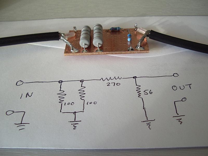
There are numerous websites that will design an attenuator for you given the working impedance and amount of attenuation required. I was not looking for precision – I would be surprised if the output of either of my radios was within 10% of the selected power anyway – and moreover I wanted to build it now using parts from my junk box not have to send off for some exact values and wait for several days for them to arrive. My attenuator was built as shown above and gave a 1.2:1 SWR over the HF range which was good enough for my purposes.
I started yesterday evening running 10mW on 80m into my end loaded attic dipole. I received no spots at all initially. I was puzzled as to why I could hear the WSPR audio using the K3 monitor even though the extension speakers I use with the K3 were switched off. I was about to compose an email to Elecraft enquiring whether the last firmware update had the effect of routing the monitor audio to the internal speaker even when an external speaker is connected when I realized the sound was coming from the computer speakers! Windows had decided to renumber the sound cards since I last used WSPR and although the receive channel was still the same and spots were being decoded the transmit audio wasn’t going to the radio. Doh!
Some time after I began transmitting I received a couple of spots from G3XLW 478km away in the south of the country. But that was all. I decided to leave it running overnight and received spots from David off and on throughout the night. These were augmented in the morning after 0800z by three spots from M0DDT at a distance of 355km to the south east. Not as impressive as Roger’s results. I guess my attic dipole, being very low for an 80m antenna, is a cloud-warmer and sends most of the RF straight up. Roger was loading the feeder of his 10m halo which doesn’t sound like much of an 80m antenna but in effect he had a top loaded vertical which probably has more lower angle radiation. That’s my theory, anyway.
It was an interesting test and I shall try very low power WSPR again on other bands. However I don’t agree with the extremist view held in some circles that people should only use WSPR with such low powers. It’s certainly interesting to discover if you can get to the end of the street on 10uW but higher powers of a few watts will reveal propagation to places lower powers won’t, information that is likely to be more useful when applied to making contacts using other modes.
NASA seeks help tracking satellite
NASA has asked amateur radio operators for help to determine if a recently launched satellite is operating. The NanoSail-D satellite was ejected automatically from the Fast Affordable Scientific and Technology Satellite, FASTSAT on Wednesday, January 19. NASA needs reports of the beacon telemetry to determine if it is operating correctly. The beacon signal is on 437.270MHz using standard AX.25 packet so APRS and packet radio operators with 70cm capability should be able to receive it.
Predictions for the satellite can be found here. Reception reports can be submitted here. Full text of the NASA press release here.


