Posts Tagged ‘Vacuum tube’
 What was your first major receiver?
I started in the ham radio and shortwave listening hobby in 1972. By 1975, this was my first real receiver. It heard very well, and ignited my lifelong passion for radio.

The R-366/TRR-5 military receiver.
This old radio, the R-366/TRR-5, which is clearly identified on the faceplate in this picture of the military rig, had great ears. It was what I used to hone my Morse code copying skills and to get the hang of how amateur radio operators conducted communications with each other, with CW, AM, or SSB. I hope someday to own one once again.
The R-366
The R-366/TRR-5 is a significant piece of military history manufactured for the Navy Department Bureau of Ships by the Espey Manufacturing Company. Built during an era when the United States Navy required absolute reliability for ship to shore and ship to ship communications, the unit is a testament to the rugged industrial design of the mid-twentieth century. Often referred to as part of the TRR-5 receiving set, this equipment frequently incorporated high quality components and precision engineering including the gold standard Collins Radio Company designs of that period. These internal components were vital in providing the remarkable stability and selectivity needed to pull weak signals out of the dense electronic noise environment found on a crowded naval vessel. It did have heterodyne squeals on a select few frequencies, which any old tube receiver was prone to have, but those did not detract from the excellent capability of the radio.
The Service
For the sailors and radio operators serving aboard ships in the 1950s and 1960s these receivers were far more than just tools for duty. In the often cramped and isolated conditions of life at sea these radios served as a critical psychological anchor. Access to the bands meant hearing the familiar sounds of home or tuning into MARS stations where amateur radio operators facilitated phone patches that reconnected sailors with their families. This bridge to the outside world was essential for maintaining morale and supporting the mental health of military personnel who were otherwise cut off from the rhythms of civilian life for months at a time. Sitting in the radio shack and slowly tuning that large central dial while listening to the crackle of the ionosphere was a meditative escape from the constant hum of shipboard operations. Many ships would pipe ball games and news shows, or music programs, over the ships intercomms, providing health and morale to the personnel.
Operating the Radio
The tactile experience of operating this specific receiver remains vivid in my memory. The layout with its distinct knobs for selectivity phasing and BFO control was designed for the hands of a professional radio operator who needed to manipulate the signal in real time. It required a disciplined ear and a steady hand to copy Morse code through heavy atmospheric conditions but that struggle made every successful reception feel deeply rewarding. It taught me the patience and technical appreciation that have defined my amateur radio hobby for decades. Owning and using a piece of history like this represented a connection to the generations of operators who stood the watch before me.
Traveling the World…
With this historic military receiver, I discovered an entire world as a child in the mid 1970s. I spent countless nights in the quiet darkness of my room with only the warm orange and yellow glow from the vacuum tubes leaking out of the back and top grills and slots of the radio enclosure, as those hot tubes cast soft light on the ceiling and walls. That radio allowed me to travel the globe from my listening position often sitting cross-legged on the floor in front of this big rig. Those late night listening sessions, when I should have been sleeping, ignited a lifelong passion for understanding the vast and interconnected world of shortwave radio as well as medium-wave DXing. I heard International Shortwave Broadcast stations as well as AM broadcast stations from Europe, Asia, the South Pacific, the Atlantic regions, South America, Central America, and North America–all over the world! I listened to amateur radio operators on Morse code, SSB, and AM modes. Ships at sea, aircraft doing transoceanic flights, fishing vessels comms where fishing captains would chat with other boat captains, and even military communications were all at my fingertips on the dial of the radio as I listened to these exotic places by headphones. I even picked up a station from Peru, South America late one night, on the mediumwave broadcast band. That is how great that receiver could hear. Of course, I had a very excellent outdoor dipole antenna that was cut for 160 meters.
What Receiver Was Your First?
What was your first major receiver? Was it just a receiver, or was it a transceiver? When was that? What did you hear that captured your imagination? Do you still have that radio?
I hope to someday have this R-366/TRR-5, once again.
~ Happy DX!
NW7US
Philco Tropic Model 3012
Last weekend I attended the Houston Vintage Radio Association holiday dinner & picked up a Philco Tropic Model 3012 during the fundraiser auction. I had let a few other radios go without placing a bid and was beginning to think I might go home empty handed when I saw the Philco “on the block”. A few seconds later I was the proud owner of this vintage receiver.
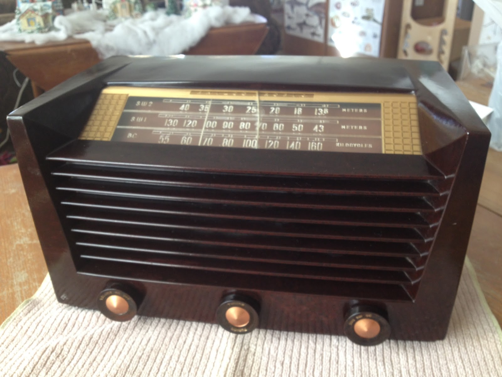 |
| Philco Tropic 3012 |
Information on this model seems a little scarce, however the style of case was introduced by Philco in 1951 and used in their line of AM/FM receivers for many years after that. This particular example is a transformer-less AC/DC set with a potentially live chassis and the unusual (to me) lineup of 14Q7, 7B7, 14B6, 35A5 & 35Y4 vacuum tubes.
What prompted me to bid on this particular radio was the inclusion of two shortwave bands in addition to the typical AM broadcast band. The dials are marked off in meters which also appealed to the ham radio side of my interests.
After attaching a short length of wire as an antenna I was able to pick up signals across the two SW1 & SW2 bands so I’ll be interested to see what it can receive with a long wire antenna at night.
After a gentle cleaning with dilute mild detergent to remove dirt I rubbed in some beeswax polish to restore the original gloss. Sadly the plastic dial is cracked in the middle but I can look past that given its a little more unusual than the typical All American Five receiver.
Being over fifty years old I wonder what this radio has been used to listen to and what stories it could tell. Perhaps it gave some youngster his or her first taste of ham radio, listening to shortwave stations and AM QSOs until they received the final demand to, “Switch that radio off and GO TO BED!”
Vacuum tubes could revolutionize computer chips?
No, I’m fairly sure I haven’t lost my mind … that really is the right headline.
 According to a resent paper published in the American Institute of Physics, nanoscale vacuum “tubes” manufactured using conventional chip making techniques have operated at frequencies as high as .46 THz.
Dr. Meyya Meyyappan, Director at the Center for Nanotechnology at the NASA Ames Research Center, has highlighted the advantages of nanoscale vacuum devices which include resistance to hard radiation and significantly improved operating frequencies.
![]() The increased operating frequency comes about because of the speed at which electrons travel through different materials. The speed of electron travel through silicon is comparatively slow, through graphine it is approximately 100 times faster and through a vacuum it approaches the speed of light.
The increased operating frequency comes about because of the speed at which electrons travel through different materials. The speed of electron travel through silicon is comparatively slow, through graphine it is approximately 100 times faster and through a vacuum it approaches the speed of light.
While the cavity is not technically a vacuum it contains so few atoms of any other material, such as oxygen, it is functionally the same. This also gives the vacuum nanoscale device an advantage in space where hard radiation can disrupt an electron’s travel through silicon leading to errors or sometimes permanent failure.
Dr Meyyappan estimates that vacuum nanoscale components will run ten times faster than the best conventional silicon chips and who knows what advances the future will hold. Faster chips will aid in signal processing and more capable software defined radios.
Do you want to monitor every CW & PSK31 transmission on the 40M band at once? With a vacuum “tube” rig you may be able to!
The further adventures of the Heathkit AT-1
Work has been conspiring to eliminate my spare time but I was able to spend a few hours over the Easter holiday to clean up the shack and make space to put the Heathkit AT-1 on the desk again. I have been able to spend a little time going over parts that need to be replaced and making a list.
 |
| The Heathkit AT-1 chassis with case and VFO-1 behind. |
There doesn’t seem to be any show stoppers although the wafer of the meter switch has broken in two and will need to be repaired. If I’m not able to repair it then thankfully it is fairly simple and replacement rotary switch can be substituted.
This isn’t going to be a museum quality restoration but the changes that were made to this transmitter in the past were sensible and if left in place are representative of period modifications. The original meter for example was not the highest quality and a Western or Simpson replacement would be an improvement. The original slide switches have been replaced with period snap-toggle switches which are also an improvement over the original.
The Heathkit VFO-1 however has been modified for grid-block keying which is a significant departure from the original and I plan to revert it back to cathode keying. Although a technical improvement it is not in keeping with the original design and needs to be undone. Everyone will have their own opinion but I think if I wanted modern circuits I’d get a more modern rig, so the VFO-1 will be returned to stock.
Hopefully I can carve out a bit of time here and there to work on this and slowly return it to working condition.
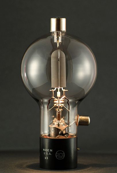
Making a Type C Triode – Amazing Glasswork!
Ron Soyland is at it again and creating a Type C Triode vacuum tube. For a look at other creations click on Making a Spherical Audion Tube by Ron Soyland
A general purpose triode originally made for use by the Royal Air Force (Great Britain) in 1918 and designed by Captain H. Round of the British Marconi Co. around 1913. It is a triode that was meant for high gain high frequency use and has a 3 volt directly heated cathode.
EICO Model 625 Tube Tester
I attended the Greater Houston Hamfest and as I walked past the tables of equipment I wondered if interest in vacuum tube equipment was starting to wane. Compared to the last few years the prices of collector quality gear had held steady but parts and restorable gear seemed to be going for less. I’d like to know your thoughts if you’ve noticed trends one way or the other.
I was happy to pick up a EICO Model 625 tube tester for $15. It is in good condition and appears to work well. The roll of settings for each tube is in good condition and a little searching on the internet supplied settings for older tubes like the number 78 in the picture below.
 |
| EICO Model 625 Tube Tester with a number 78 tube |
The EICO 625 is not a top of the line tester but it does basic tests and will let you know if a tube is functioning and an idea of the life left in it. It was sold in kit form for $34.95 in 1958 which is roughly equivalent to $274 in 2012.
 |
| Inside the EICO 625 from diyaudioprojects.com |
The EICO 625 is fairly unique in having its own 6H6 diode tube to rectify the 30V filament voltage. It provides DC for the neon short-indicator bulb. If the tube is suspected of having a short then there is a fairly comprehensive series of tests than can be administered to isolate shorted elements.
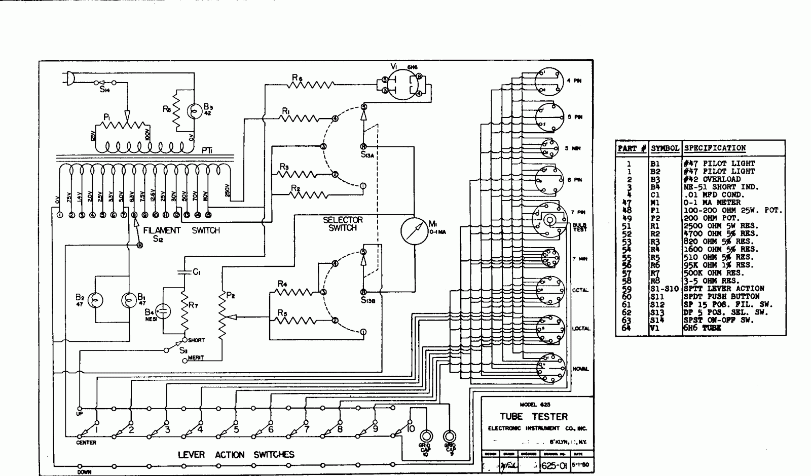 |
| EICO Model 625 circuit diagram |
Here is the complete TUBE TEST DATA 1/1/78 for the EICO Model 625 Tube Tester
Excellent information on servicing and calibrating your Classic emission tube tester.
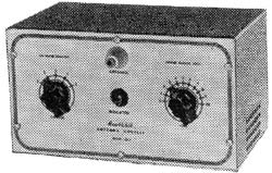
Heathkit’s first amateur transmitter – Heathkit AT-1
The Heathkit AT-1 represents the commercial embodiment of the simple Master Oscillator Power Amplifier (MOPA) transmitter using a crystal controlled 6AG7 oscillator plus a 6L6 final output tube.
Although it was possible to design and build a simpler transmitter, the goals of output power and stability could become mutually exclusive when trying to operate with only one tube. For a novice class license holder of 1951 the Heathkit AT-1 represented a solid performing rig that would be relatively easy to construct and operate.
The Novice remained the primary entry license until the Morse code requirement was eliminated for Technician licenses in 1990. On HF it permitted code transmissions only, with a maximum power of 75 watts, (input to the transmitter’s final amplifier stage) on limited segments of the 80, 40 and 15 meter bands.
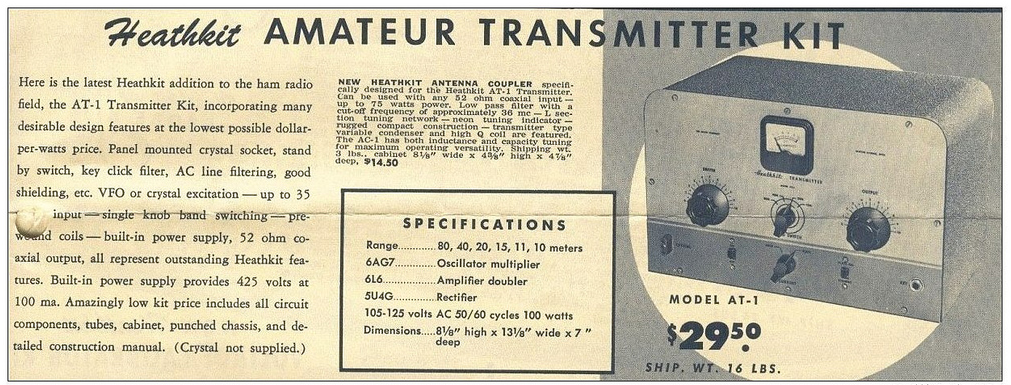 |
| For $29.50 and the loan of a few tools you could get some use out of that new novice license |
The earlier MOPA circuit from the ARRL handbook of 1941 below shows a layout remarkably similar to the circuit of the AT-1 although it is designed for plug in coils rather than the band-switching arrangement of the later Heathkit transmitter.
| MOPA transmitter using a 6L6 and an 807 as the power amplifier (ARRL Handbook 1941) |
For a little added complexity MOPA transmitters generally offered better stability of frequency and keying waveform than single tube crystal controlled or self exited rigs. The straight forward design of the AT-1 should have looked familiar to novice class hams after studying the ARRL handbook or other radio publications.
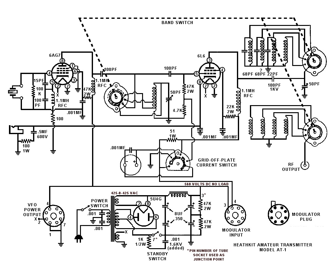 |
| Heathkit AT-1 Circuit diagram showing band-switching arrangement and link coupled output |
Once the novice had upgraded his license the AT-1 could be expanded by the addition of the Heathkit VF-1 variable frequency oscillator to allow transmission on any frequency within the allowed band.
 |
| The Heathkit VF-1 Variable Frequency Oscillator |
The VF-1 covered 160-80-40-20-15-11-10 meters and used an OA2 voltage regulator tube to provide a stable voltage for the oscillator. Ceramic coil forms, solid construction and high quality components were used to help increase stability.
 |
| The Heathkit AC-1 Antenna Coupler. Designed to attach to a single wire by the insulated post on the front panel. |
 |
| Heathkit AC-1 Antenna Coupler circuit diagram |
Although Heathkit did not produce a AM modulator for the AC-1 there is provision for modulator connection on the rear panel. The earlier ARRL manuals have several suitable circuits for modulators that would work with the AC-1. Most functioned by driving a modulation transformer with the output from an audio power amplifier. The secondary of the modulation transformer would be carrying the DC plate supply for the power amplifier tube plus or minus the instantaneous voltage of the audio waveform. By changing the plate voltage to the final amplifier tube the radio frequency output would be controlled by the amplified audio frequency resulting in amplitude modulation.


