With all of Elecraft's radio kits the builder is able to purchase
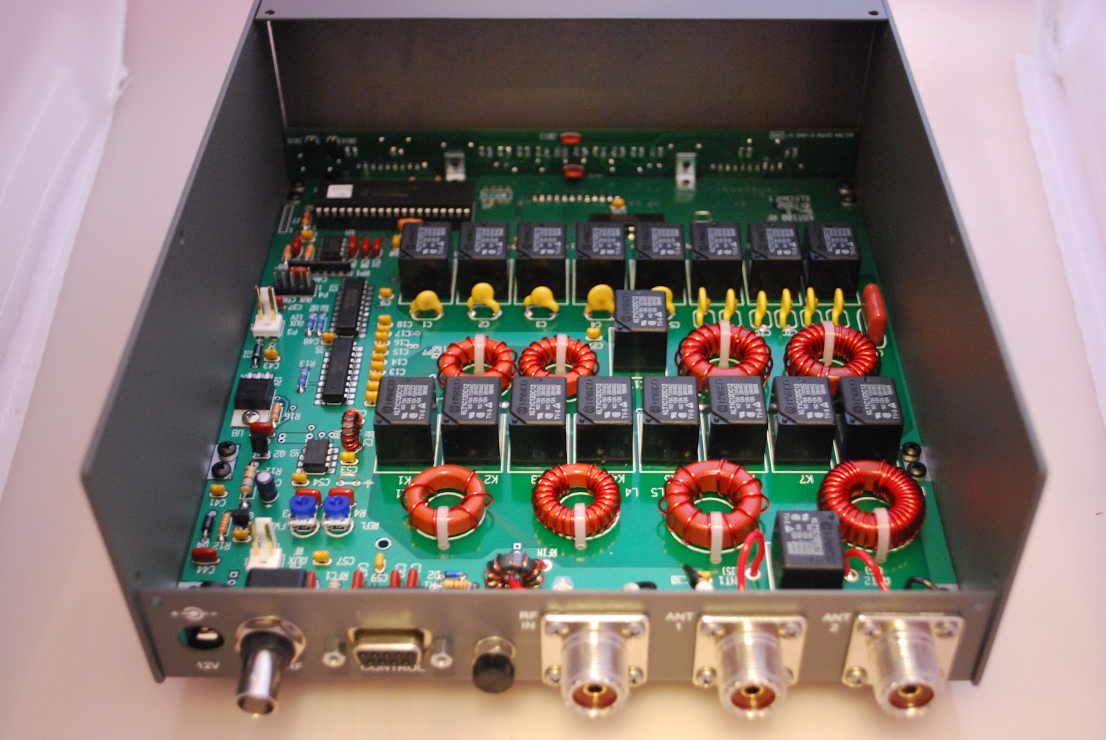
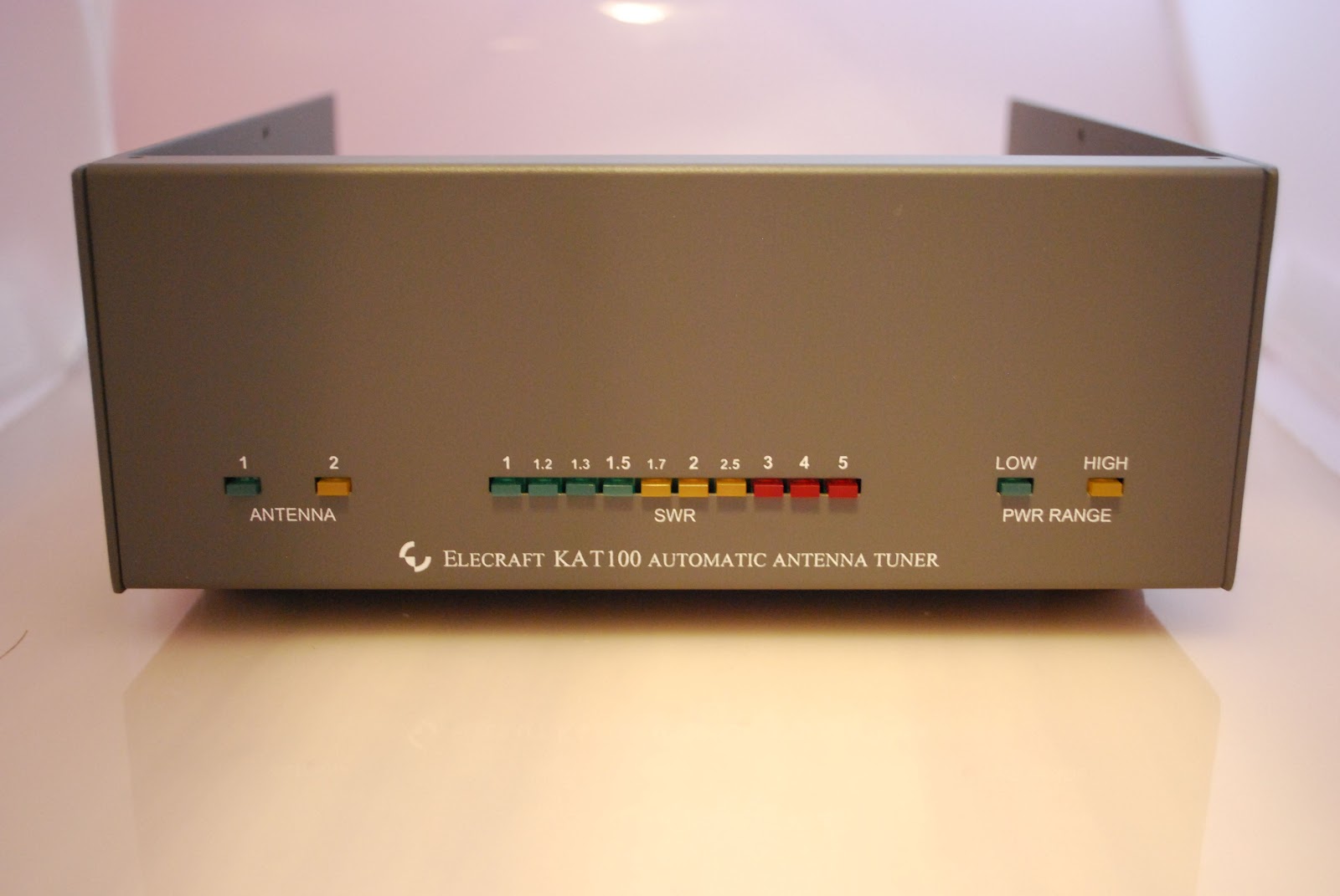
add-on's to the radio either as needed, when able to afford them or if you want to expand into a new area of ham radio like FM or digital. At this point I am adding the KIO2 to my Elecraft K2, I want to remote mount the 100 watts amp (KPA100) and the antenna tuner (KAT100). To do so my next project is to build the KIO2 module. By adding this unit I am able to communicate with the K2 through my P.C. Also the K2 can operate along side the external amp and antenna tuner. So back to the KIO2 project.....the first step in the assembley is to mount two brass nuts to
 |
| Soldered nut |
the 9 pin D connector (DB9F). To make this part of the project go smoothly you begin by change the tip on your soldering iron. I have the
Weller WES51 soldering station it is a 50 watts unit and has been very reliable. I am able to change from a very slender tip to a larger tip for better heat transfer. I also add a little bit of solder paste to the nut and chassis of the DB9F. This helps the solder flow from part to part. Finally I have a larger diameter solder just for these types of jobs. This allows me to feed the solder to the spot were needed and I am able to get more flow of solder to that spot at one time. The next step seemed impossible to me at first, I was to press the small PC board between the top and bottom rows of the DB9F
 |
| DB9F installed |
connectors. After a few gentle tries and not successful I gave the board a good push and it did slip on and was a solid mating between the board and connector. At this step you may have to give a little elbow grease but the board will actually mate with the connector. Next I had to mount a 16.289 Mhz crystal care has to be taken as you can damage the crystal very easily with the heat from the soldering iron. The tip on the iron
 |
| Soldering on the can |
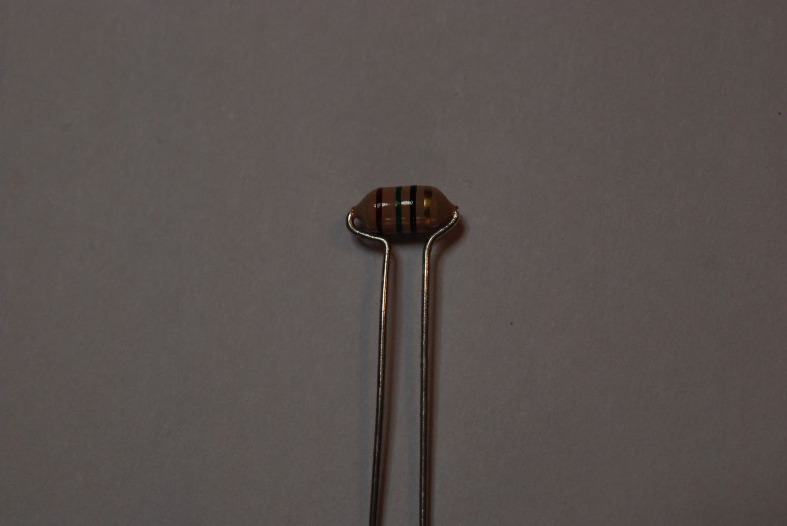
has to be changed back to the smaller tip enabling you to solder the crystal to the PC board. Once that is done a ground has to go from the top of the crystal (the can) to the PC board. To do this you must take the time to change the Weller tip again to the larger tip. Failing to do this and trying to do it the "fast" way may result in damage to the crystal or a poor solder job.....but most likely it will be both. Thus no time will actually had been saved. A discarded terminal lead is used for grounding. I start by forming the lead to fit properly. Then tin the top of the crystal add a little flux to the formed component lead. Put the lead on the top of the can of the crystal and add solder. Doing this way allows you to keep the soldering iron tip on the can for very short intervals. Now it's a simple case of mounting resistors and cap's after changing the Weller tip to the smaller tip. The inductors have been
 |
| Bending inductor leads |
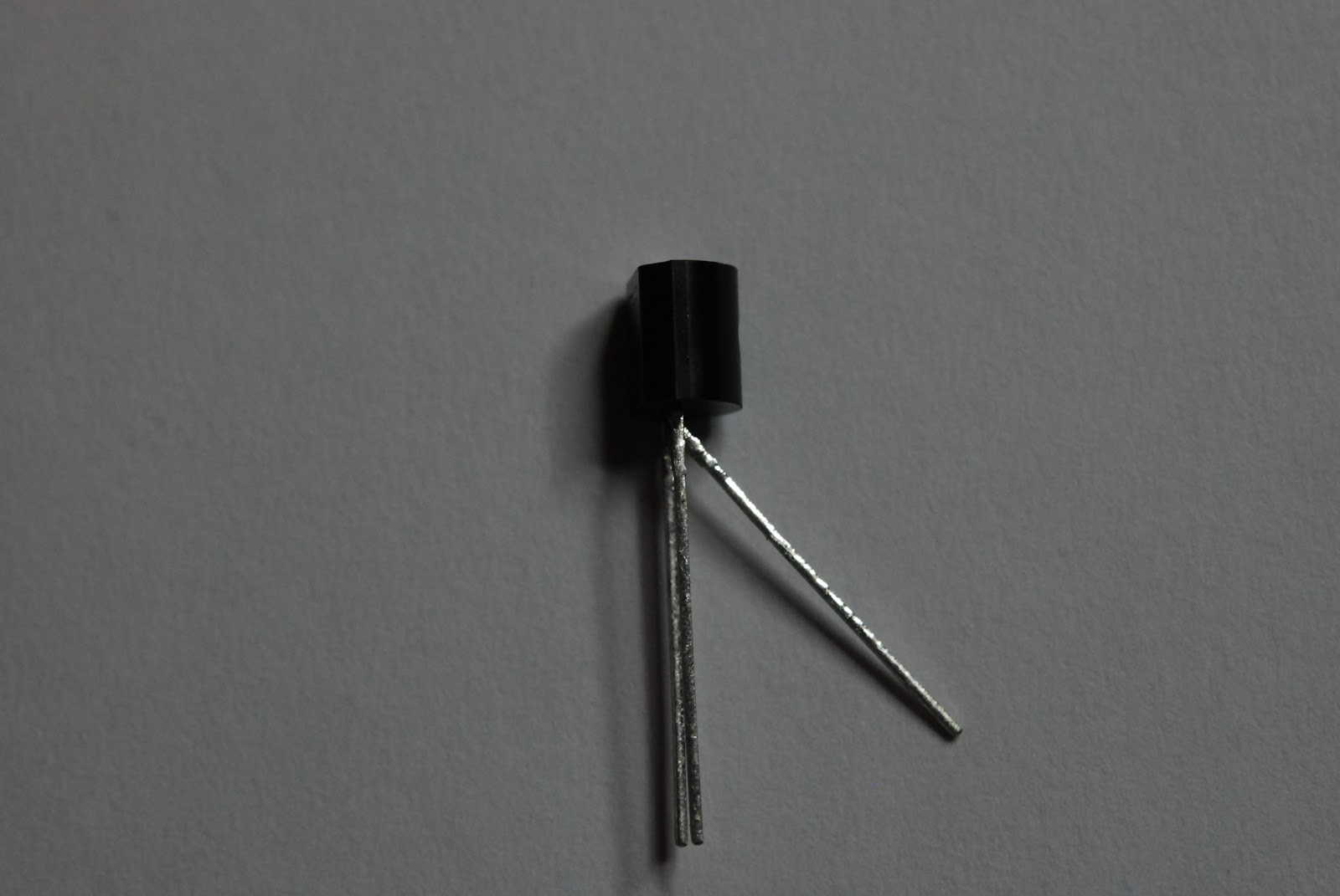
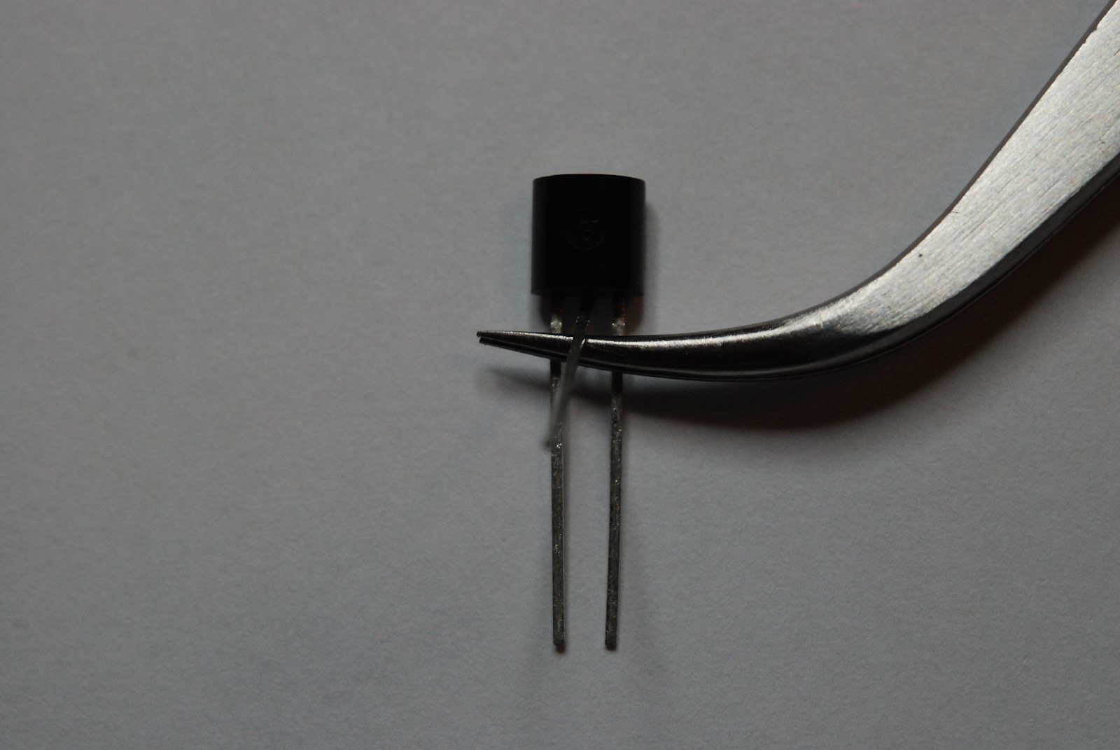
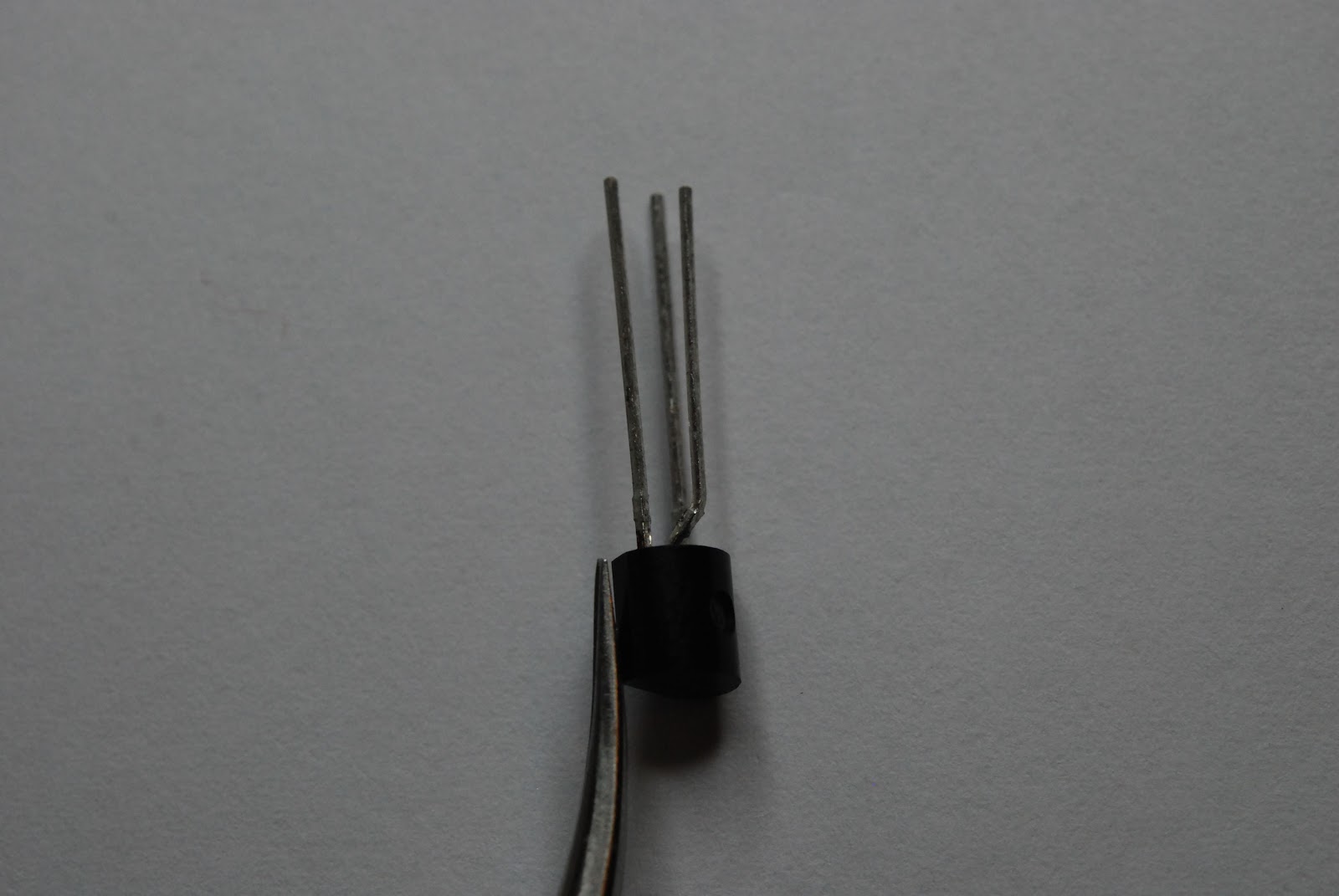
upgraded by Elecraft to a larger current carrying inductor. Because of this the leads have to be bent to allow component leads to fit onto the board. While on the subject of bending leads I have always had fun getting the three leads of the transistors and voltage regulators lined up with the outline on the PC board. I found a way that works almost all the time and is very simple...just the way I like it.....I use a pair of my tweezers to bend the center lead out and away from the two outer leads. Then I slide the tweezers between the center lead and two outside leads. The I simply bend the center lead upright. The tweezers
 |
| Middle lead bent outward |
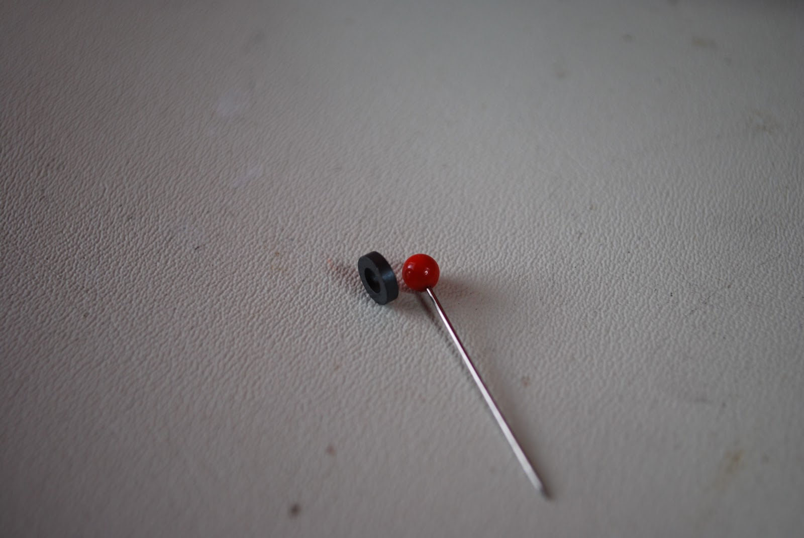
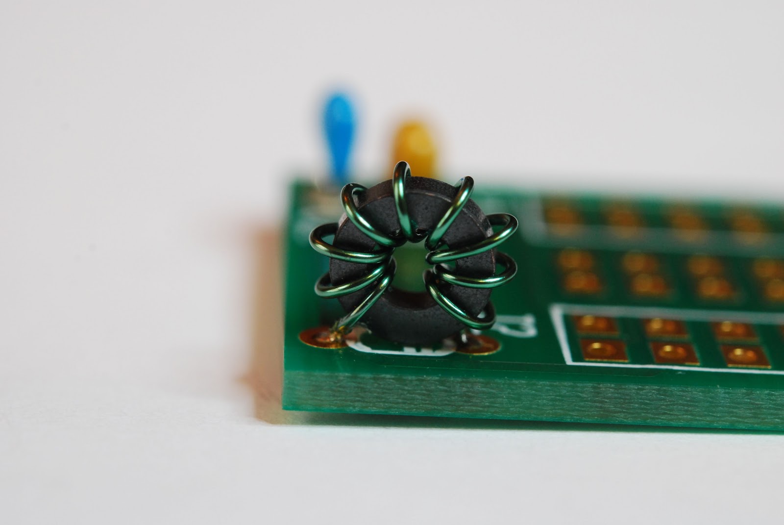
seem to provide the spacing that is needed for the component to fit into the board nicely. I have wound many toroids in my kit building days but the KIO2 board has the smallest toroid I have ever seen!!! Also this toroid does not have rounded edges but sharp right angle type edges, I didn't think this would be an issue until I started to wind the toroid. The first winding adventure had me removing the enamel coating on the #26 wire. As I wound the toroid the wire enamel was scrapped off but the sharp edges on the toroid core. It was time to unwind the toroid and re-evaluate the way I am going to wind this darn toroid. In the past as I threaded the wire threw the core it would ride along the cores edge and I pulled
 |
| Tweezers inserted then bend lead |
the wire tight. Doing this just scored the heck out of the wire. The toroid was to have 12 turns which meant the wire would be very close to each other so I did not want any shorts. It's easier to fix this now by rewinding the toroid than later removing it on the completed board. I overcame this problem by not allowing the wire to touch the core edges as I was winding. Always keeping a large loop in the wire
 |
| Pin and toroid |
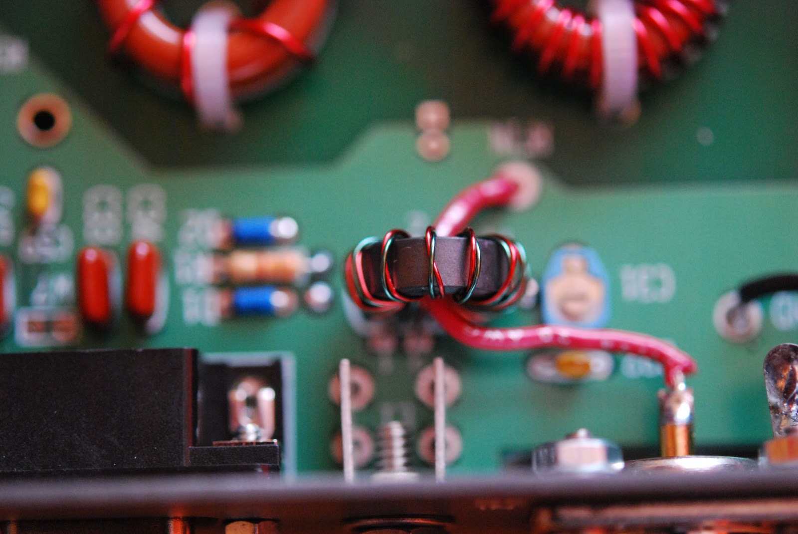
around the core seem to do the trick. As I closed the loop the wire was allow to rest gently on the toroid it was NOT pulled tight as with other smooth toroids. There were two changes I had to make to the KIO2 the first was adding a 9 turn toroid in place of a smaller inductor at the L1 position. When remote
 |
| End result |
mounting the 100 watt amp and antenna tuner the KIO2 has to control more. When it does the the current draw goes up as well. The inductor supplied with the KIO2 is rated around 15 mA with the added KPA100 the draws 65 mA at idle. The advice is to replace the inductor with an 8-9 turn FT23-43 toroid. Elecraft was great in
 |
| Keeping wide turns |
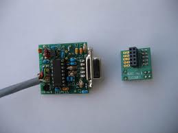
shipping me the toroid I needed and the wire was well. There was a bit of confusion on my part regarding L1, the kit comes with two PCB's on KIO2 and the other AUX2. I assumed the L1 position on the KIO2 board was the spot for the new toroid....but it's not. You also have an L1 position on the AUX2 board and this is were the new toroid is placed. The other change that has to be made is the cabling from the KIO2. Normally there is just a cable from the K2 over to your PC and that's it. When you remote mount the KPA100 and KAT100 the cable path now must not only go to your PC but to the
 |
| New L1 Toroid |
KPA100/KAT100 combo as well. So there is an additional cable that has to be soldered to the DB9M connector going to the K2's DB9F. This is the reason for adding the larger inductor as more power will be required of the L1 inductor. It's like it is doing double duty. For most of my PCB board handling needs I find
 |
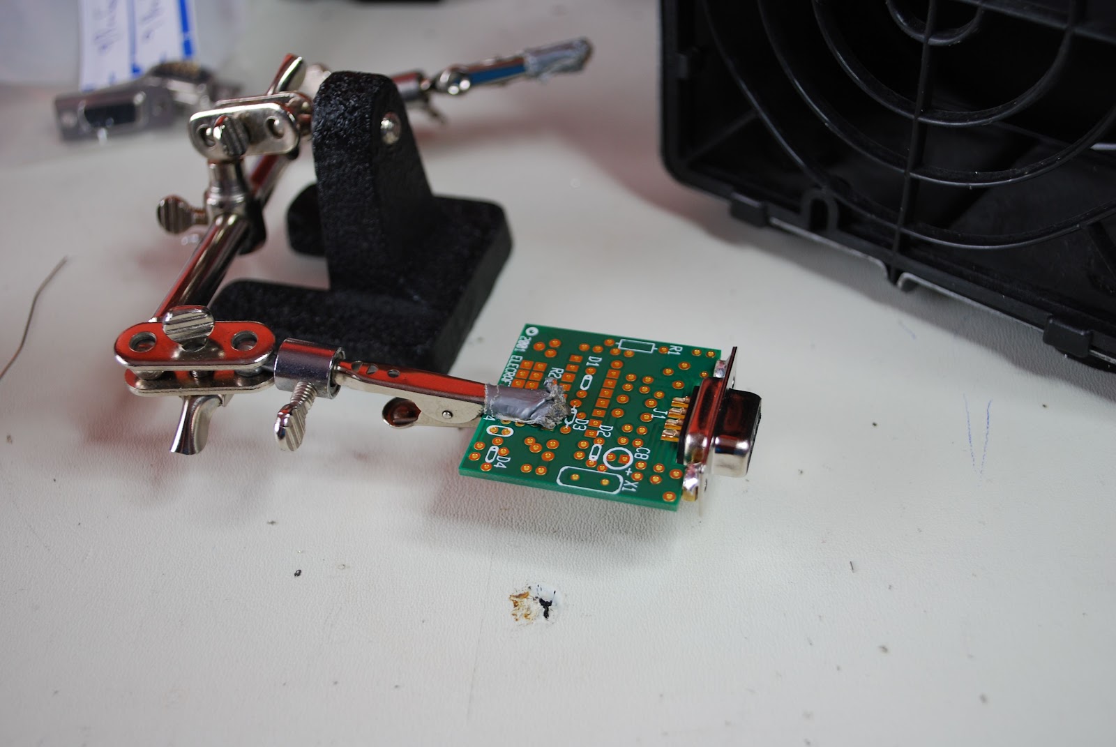
| Alligator clip vise |
my
Panavise to do the trick. For soldering the interconnecting cables to the DB9M I find the
alligator clip type vise works great. I can place all the wires in the DB9M and solder them all at once. The final step in the construction is to add an 8 conductor cable from the KIO2 board to the AUX board. The Elecraft instructions ask you to strip, tin and place each of the 8 conductors in the designated holes on each board then solder. When I did this I found the individual wires coming out of the PC board. I then soldered the first 2 set of wires in place and it was much easier to then instal the rest and solder them in. It's
 |
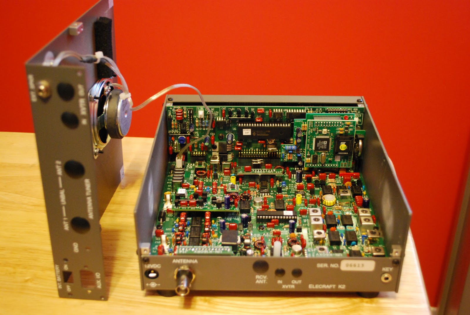
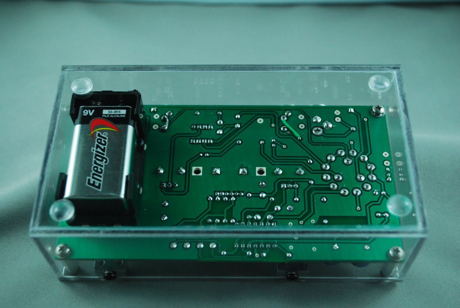
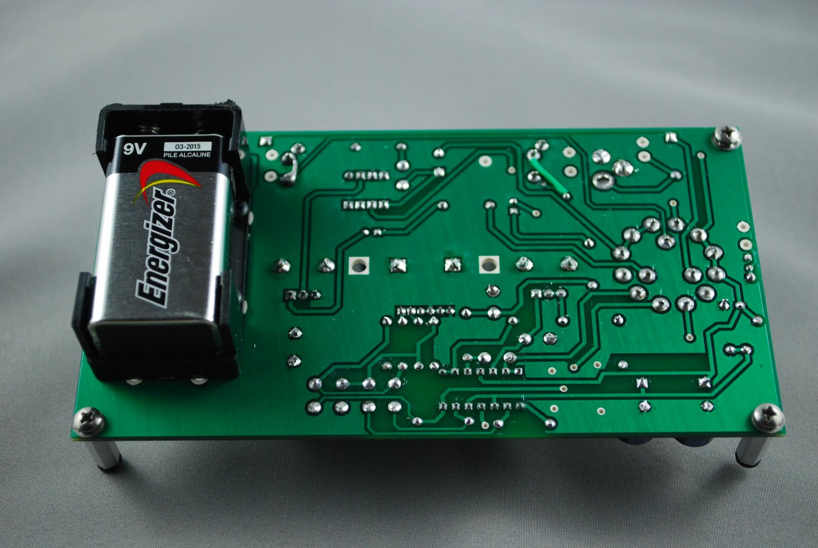
| installing in K2 |
done and installed in the K2 time to test it and move on to getting the K2 into portable/home mode but that is a whole new post.
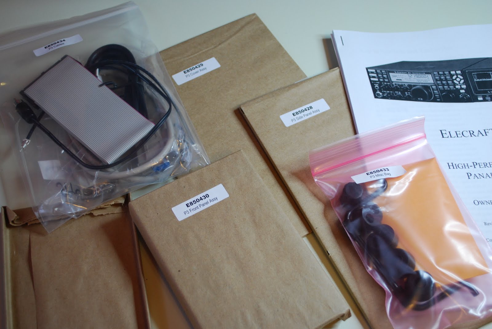
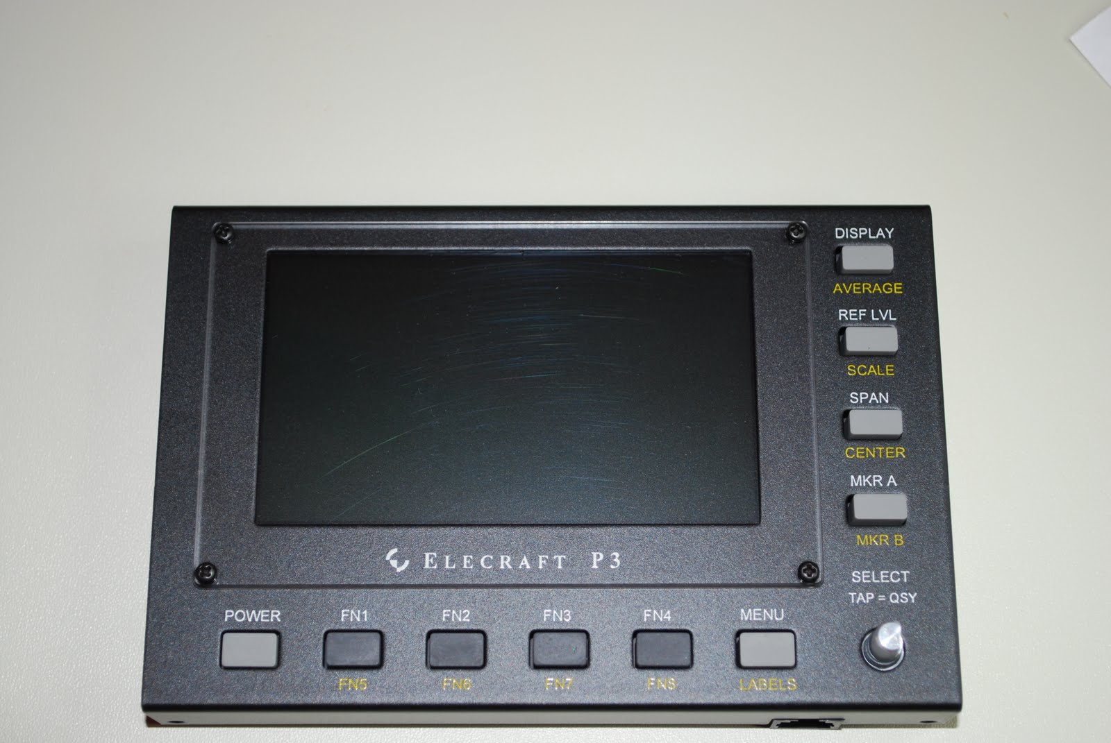
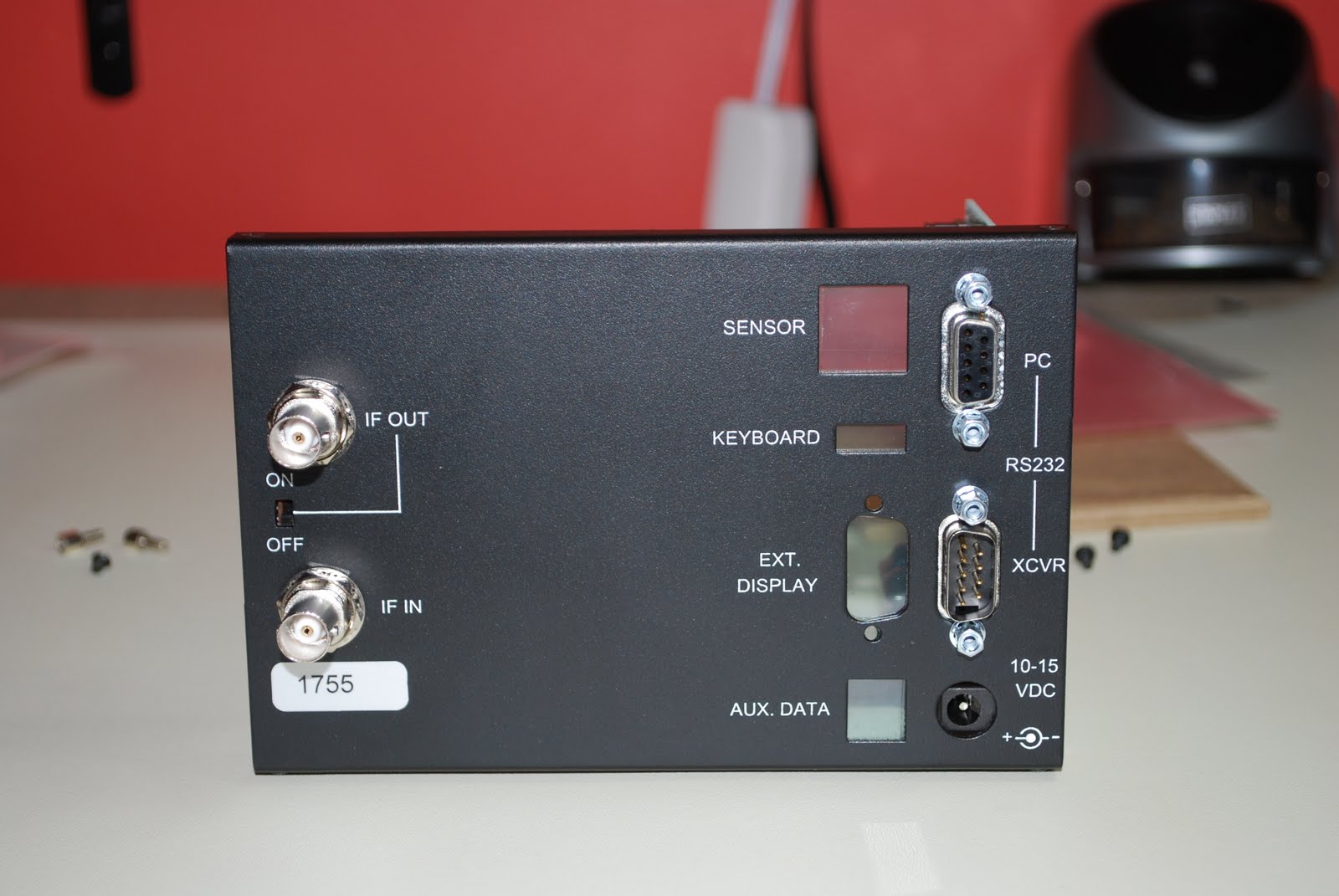
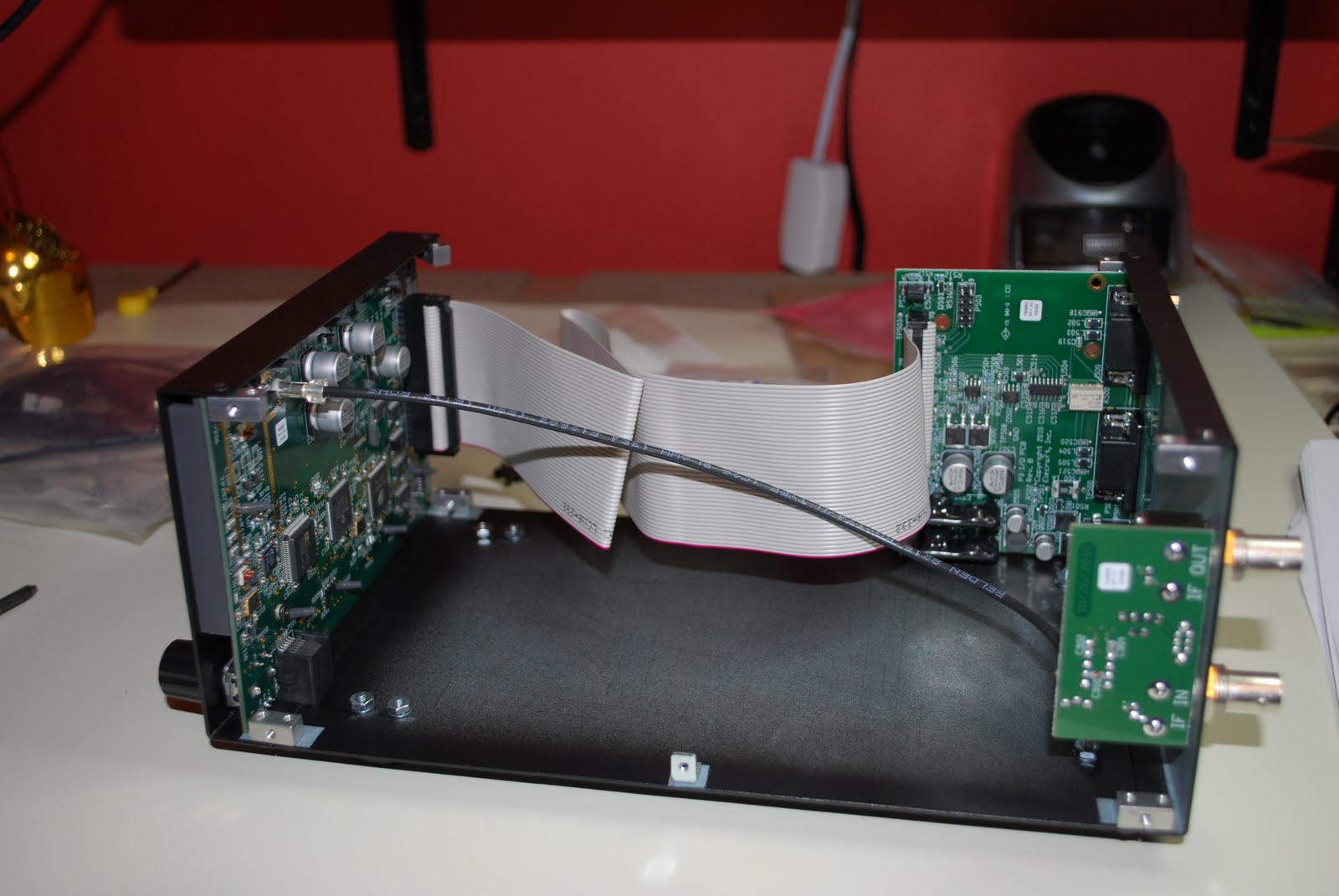
 The Elecraft P3 has arrived……
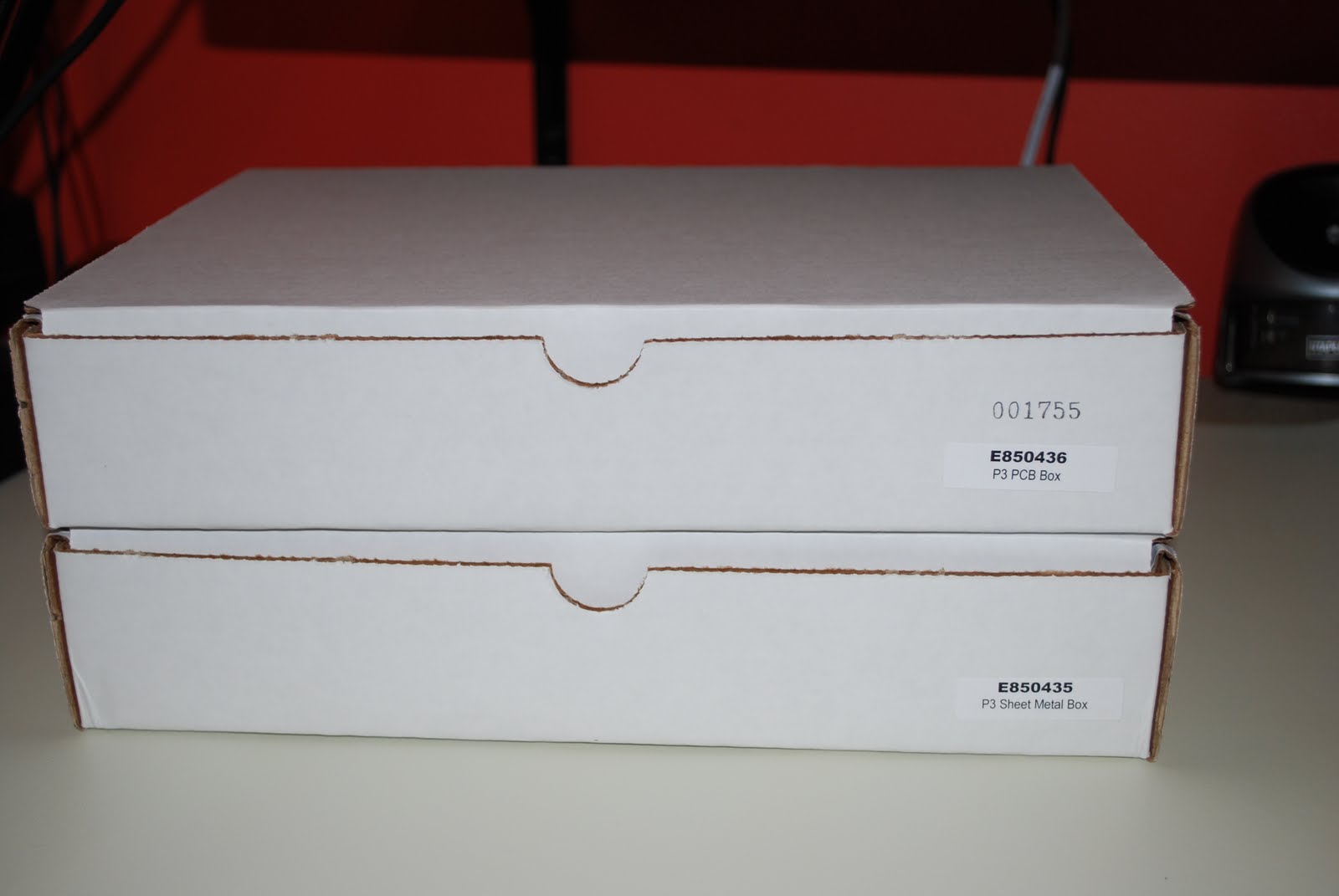


