Posts Tagged ‘Morse Code’
 Arduino CW decoder – Conclusion
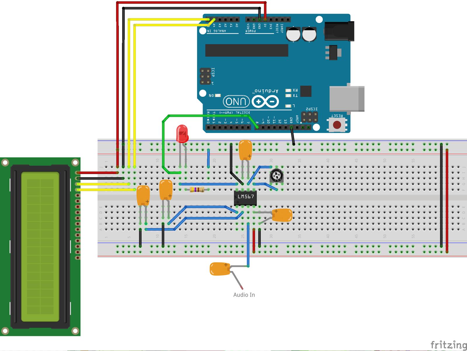
1. Line in or Microphone input
2. Easy to read display – all boxed neatly
3. An LED that shows the Zero beat
4. Easily accessible Reset Switch
5. Powered from a 12v supply.
I did want to create a usable PCB, something that could be used by a student or someone wanting to build the kit. So using the Fritzing application I set about laying out a circuit board.

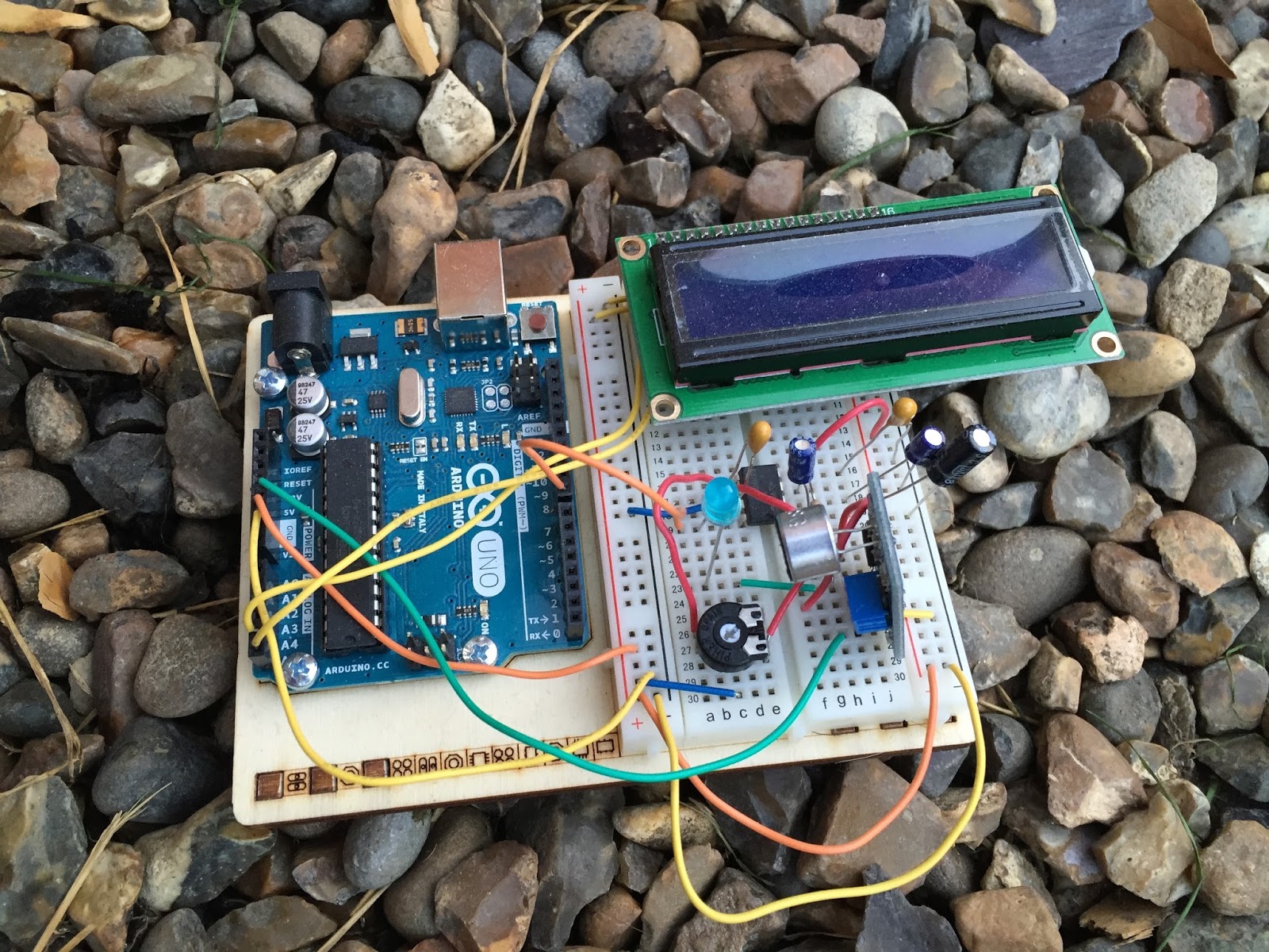
This was my very first attempt at creating a PCB , so nerves were a wee bit on the tense side. I also wanted to box the project, so my rationale was to find a box first to work out the physical dimensions of the finished project.
As with the Vero Version – I created a layout that would fit on top of the UNO.
After submitting the design, and waiting a week I managed to get hold of 3 boards. They looked awesome. All white and exactly how I laid them out.
I did make 2 small errors on these boards. The first issue was sitting the capacitors a bit too close to the LM567 IC. That is an easy fix for the next version. But the 2nd and more serious issue is I forgot to ground 2 caps. They were floating and in parallel. I did fix this by attaching a wire to ground from one of the caps. That solved the issue, and I have already corrected the fault for the next batch of boards.
2 further observations of the boards & the project as a whole have highlighted 2 further improvements to the project. The location of the pins for the display / reset switch and audio OUT should be on the other side of the board. That would make a far better layout. Also adding in an audio oscillator / switch & plug to insert a key on the oscillator – then feed the output to the Arduino would immediately mean this kit could be used as a practice oscillator too. – that would show the letters as you transmit them out.
So here is a review of the project so far, and what I intend to do with the project going forward.
Arduino CW decoder – Conclusion
1. Line in or Microphone input
2. Easy to read display – all boxed neatly
3. An LED that shows the Zero beat
4. Easily accessible Reset Switch
5. Powered from a 12v supply.
I did want to create a usable PCB, something that could be used by a student or someone wanting to build the kit. So using the Fritzing application I set about laying out a circuit board.
This was my very first attempt at creating a PCB , so nerves were a wee bit on the tense side. I also wanted to box the project, so my rationale was to find a box first to work out the physical dimensions of the finished project.
As with the Vero Version – I created a layout that would fit on top of the UNO.
After submitting the design, and waiting a week I managed to get hold of 3 boards. They looked awesome. All white and exactly how I laid them out.
I did make 2 small errors on these boards. The first issue was sitting the capacitors a bit too close to the LM567 IC. That is an easy fix for the next version. But the 2nd and more serious issue is I forgot to ground 2 caps. They were floating and in parallel. I did fix this by attaching a wire to ground from one of the caps. That solved the issue, and I have already corrected the fault for the next batch of boards.
2 further observations of the boards & the project as a whole have highlighted 2 further improvements to the project. The location of the pins for the display / reset switch and audio OUT should be on the other side of the board. That would make a far better layout. Also adding in an audio oscillator / switch & plug to insert a key on the oscillator – then feed the output to the Arduino would immediately mean this kit could be used as a practice oscillator too. – that would show the letters as you transmit them out.
So here is a review of the project so far, and what I intend to do with the project going forward.
CW decoder – The Arduino
 This is arguably the simplest part of the project. As mentioned Budd Churchward had created a series of videos on how he wrote the Sketch, created a PCB and published his code. (Budd’s Sketch is available here)
CW decoder – The electronics

CW decoder – The electronics
CW decoder – Introduction
 If you do follow me on twitter (and if you don’t – you really should) you will have no doubt seen my recent tweets about constructing a CW decoder. After a number of retweets, and favorites from other very interested hams – I did promise that I would collate all my knowledge into a blog posts and share the details with you all.
So, for those who have not been following me on twitter – here is the sales pitch. I recently started looking at some projects that I could get my Arduino Uno involved in with the radio hobby. I have a number of reasons why I want to combine radio, Arduino and some electronics – more about this later.
I stumbled across a video on YouTube where Budd Churchward showed his Arduino copying and decoding CW straight off the HF band and at a reasonably high speed. I ventured further and wanted to know what electronics Budd was using to achieve this excellent little project.
I used the limited shared knowledge and discovered that the electronics is basally a LM567 – Tone decoder chip that (I have since discovered the chip is used in the ARRL book for Arduino Projects) I discovered takes an audio input and converts this to a HIGH / LOW output suitable for the Arduino to use as a signal for decoding.
Finding a suitable project for the LM567 and trying to work out how fellow constructors had configured their LM567s was not an easy task. This did indeed take quite a lot of chasing and head scratching. I will go into more technical detail on the next post – but for the reason why I wanted to complete this ? very simple. I w
ant to create a project that would “inspire” young electronically minded students that might have an interest in radio – (i.e the morse code) some coding experience and some construction / electronic interest. This project covers all 3 areas, and only lightly covers each subject area.
In the next post – I show the LM567, the schematic and give you the list of parts required.
CW decoder – Introduction
If you do follow me on twitter (and if you don’t – you really should) you will have no doubt seen my recent tweets about constructing a CW decoder. After a number of retweets, and favorites from other very interested hams – I did promise that I would collate all my knowledge into a blog posts and share the details with you all.
So, for those who have not been following me on twitter – here is the sales pitch. I recently started looking at some projects that I could get my Arduino Uno involved in with the radio hobby. I have a number of reasons why I want to combine radio, Arduino and some electronics – more about this later.
I stumbled across a video on YouTube where Budd Churchward showed his Arduino copying and decoding CW straight off the HF band and at a reasonably high speed. I ventured further and wanted to know what electronics Budd was using to achieve this excellent little project.
I used the limited shared knowledge and discovered that the electronics is basally a LM567 – Tone decoder chip that (I have since discovered the chip is used in the ARRL book for Arduino Projects) I discovered takes an audio input and converts this to a HIGH / LOW output suitable for the Arduino to use as a signal for decoding.
Finding a suitable project for the LM567 and trying to work out how fellow constructors had configured their LM567s was not an easy task. This did indeed take quite a lot of chasing and head scratching. I will go into more technical detail on the next post – but for the reason why I wanted to complete this ? very simple. I w
ant to create a project that would “inspire” young electronically minded students that might have an interest in radio – (i.e the morse code) some coding experience and some construction / electronic interest. This project covers all 3 areas, and only lightly covers each subject area.
In the next post – I show the LM567, the schematic and give you the list of parts required.


