Posts Tagged ‘Morse Code’
 CW decoder – The electronics
 July 30th, 2015 |
  Author:
CW decoder – The electronics
CW decoder – Introduction
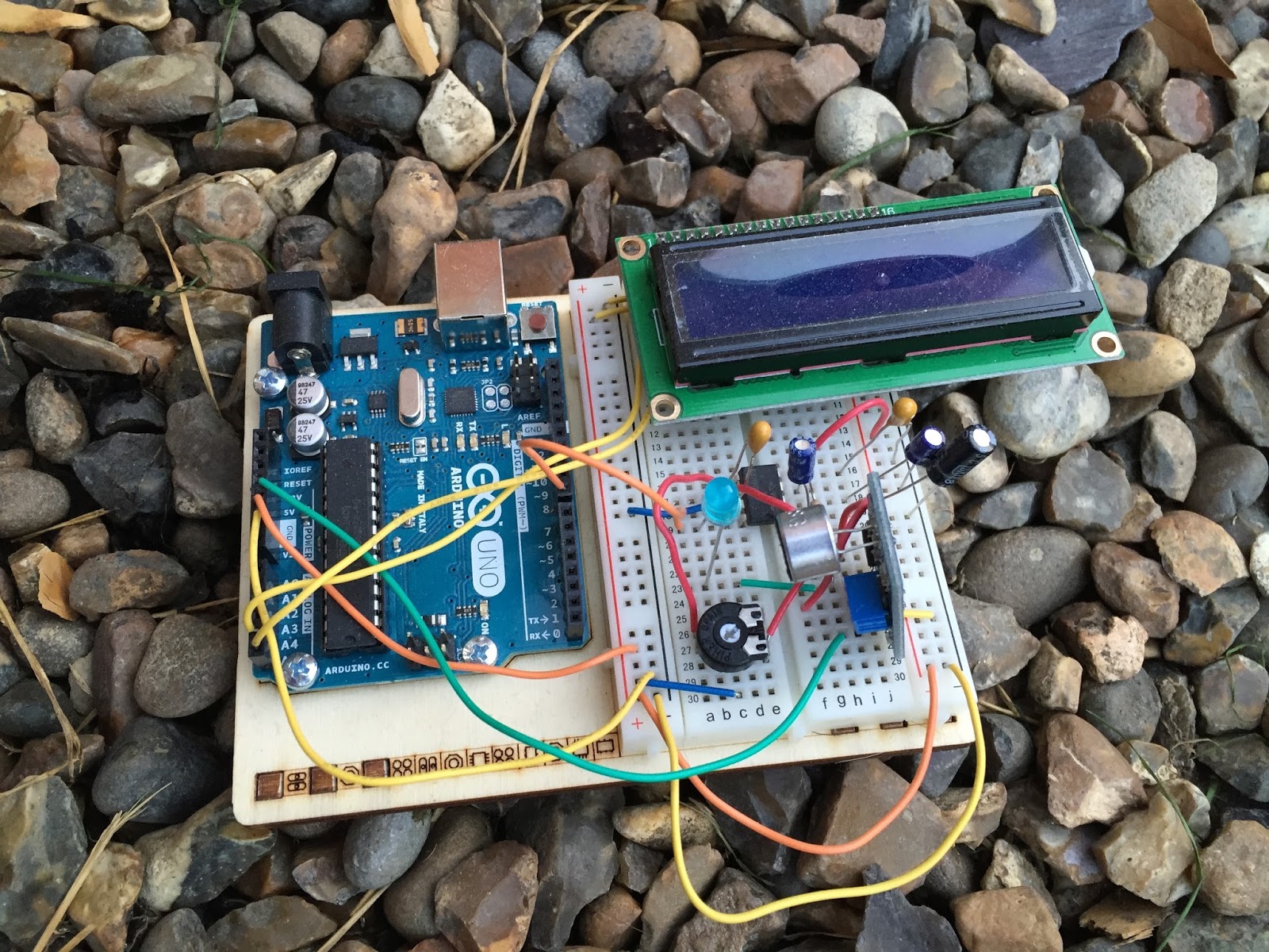 If you do follow me on twitter (and if you don’t – you really should) you will have no doubt seen my recent tweets about constructing a CW decoder. After a number of retweets, and favorites from other very interested hams – I did promise that I would collate all my knowledge into a blog posts and share the details with you all.
So, for those who have not been following me on twitter – here is the sales pitch. I recently started looking at some projects that I could get my Arduino Uno involved in with the radio hobby. I have a number of reasons why I want to combine radio, Arduino and some electronics – more about this later.
I stumbled across a video on YouTube where Budd Churchward showed his Arduino copying and decoding CW straight off the HF band and at a reasonably high speed. I ventured further and wanted to know what electronics Budd was using to achieve this excellent little project.
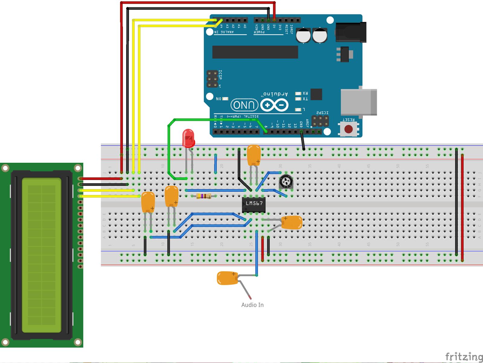
I used the limited shared knowledge and discovered that the electronics is basally a LM567 – Tone decoder chip that (I have since discovered the chip is used in the ARRL book for Arduino Projects) I discovered takes an audio input and converts this to a HIGH / LOW output suitable for the Arduino to use as a signal for decoding.
Finding a suitable project for the LM567 and trying to work out how fellow constructors had configured their LM567s was not an easy task. This did indeed take quite a lot of chasing and head scratching. I will go into more technical detail on the next post – but for the reason why I wanted to complete this ? very simple. I w
ant to create a project that would “inspire” young electronically minded students that might have an interest in radio – (i.e the morse code) some coding experience and some construction / electronic interest. This project covers all 3 areas, and only lightly covers each subject area.
In the next post – I show the LM567, the schematic and give you the list of parts required.
CW decoder – Introduction
If you do follow me on twitter (and if you don’t – you really should) you will have no doubt seen my recent tweets about constructing a CW decoder. After a number of retweets, and favorites from other very interested hams – I did promise that I would collate all my knowledge into a blog posts and share the details with you all.
So, for those who have not been following me on twitter – here is the sales pitch. I recently started looking at some projects that I could get my Arduino Uno involved in with the radio hobby. I have a number of reasons why I want to combine radio, Arduino and some electronics – more about this later.
I stumbled across a video on YouTube where Budd Churchward showed his Arduino copying and decoding CW straight off the HF band and at a reasonably high speed. I ventured further and wanted to know what electronics Budd was using to achieve this excellent little project.
I used the limited shared knowledge and discovered that the electronics is basally a LM567 – Tone decoder chip that (I have since discovered the chip is used in the ARRL book for Arduino Projects) I discovered takes an audio input and converts this to a HIGH / LOW output suitable for the Arduino to use as a signal for decoding.
Finding a suitable project for the LM567 and trying to work out how fellow constructors had configured their LM567s was not an easy task. This did indeed take quite a lot of chasing and head scratching. I will go into more technical detail on the next post – but for the reason why I wanted to complete this ? very simple. I w
ant to create a project that would “inspire” young electronically minded students that might have an interest in radio – (i.e the morse code) some coding experience and some construction / electronic interest. This project covers all 3 areas, and only lightly covers each subject area.
In the next post – I show the LM567, the schematic and give you the list of parts required.
Nifty I Phone Morse Code Decoder
HOT PAW
MORSE CODE DECODER FOR I PHONE

Screen Snap of Hot Paw Morse Code Decoder
I recently installed a ham radio station in my truck. Since then I’ve been having a lot of fun with it, using SSB mostly, since that is a novelty for me. Most of my operating has been using CW, but taking a side trip into PSK occasionally. Logging is somewhat cumbersome in a truck. I used big elastic bands to attach a small clip board to my leg so I could quickly write down a call sign and very basic information. This information would be then transferred to a computer log at home. I tried using the computer in the truck also, and that proved even more cumbersome, having the laptop jammed into the steering wheel.
I like to use a keyboard to send code but no matter what I used, it was a bit awkward in the truck. At the very least, the laptop stays put when its jammed into the steering wheel. Using the passenger seat would require my changing the radio head orientation, the antenna control and paddles which are all set up for easy use from the drivers seat.
Occasionally I’d switch to CW and fumbled for a pen to write down a call sign, time, and band. The guy I was chatting with on 40 meter CW was running just a tad too fast for me to copy ‘everything he sent’, so I missed some of it. It seems that the ‘buffer in my brain’ is smaller than I’d like it to be and with FIFO being the rule, the beginning of a word vanishes as I copy the ending.
(FIFO, First In, First Out’) Some folks may complain that using a ‘decoder’ is cheating somehow. Yes, for a contest, but for every day QSO’s its not cheating at all. If you don’t like it, don’t use it!
I discovered this app and tried it last night for the first time. Wowzah, can it copy code! Just lean it up against your radio, or just near it, and it copies CW. This is a really great help when someone is sending just a ‘tad faster’ than my ability to copy ‘everything’! Its also handy to ‘get the entire call sign’, while I was fumbling with other things in the truck! It works pretty well even in poor band conditions, and has Farnsworth Method as well as regular copy. It has ultra high speed copy, but I have not tried it. 1oo WPM code is hard to come by on the air.
This proves very useful in the truck, but my guess is that other hams will find it handy in other ways.
PIXIE 2 QRP Transceiver build
PIXIE 2 QRP Transceiver build