Posts Tagged ‘LM386’
 Simple interference fix for the Chinese Pixie
The Chinese Pixie transceiver operating at 7023 kHz has become very popular. It often costs less than 5 USD on Ebay. Like most Pixies it is susceptible to broadcast breakthrough and intermodulation. Much of this is caused by the keying circuit of the audio amplifier, the LM386. The cure is to move the muting diode from the power supply pin (no. 6) to the bypass pin (no. 7). I have described this in another blog post with title: “Using pin 7 of the LM386 to reduce BCI and add side tone to Pixie 2“.
Here are two pictures that show how this can be done for the Chinese Pixie. One needs an additional resistor in the range 10 – 47 ohms. I have used 10 ohms in the picture. It replaces the old R3 of 1 k. The diode D3 is not mounted, and instead it is mounted under the PCB with the minus (denoted by the ring) connected to where D3’s minus was, and the plus side connected to pin 7 of the LM386.
 |
| R3 is indicated by the lower left arrow, and the old placement of D3 is shown with the upper arrow |
 |
| Arrow showing where D3 instead should be soldered. The minus, indicated by the ring, is to the left in the image |
Simple interference fix for the Chinese Pixie
The Chinese Pixie transceiver operating at 7023 kHz has become very popular. It often costs less than 5 USD on Ebay. Like most Pixies it is susceptible to broadcast breakthrough and intermodulation. Much of this is caused by the keying circuit of the audio amplifier, the LM386. The cure is to move the muting diode from the power supply pin (no. 6) to the bypass pin (no. 7). I have described this in another blog post with title: “Using pin 7 of the LM386 to reduce BCI and add side tone to Pixie 2“.
Here are two pictures that show how this can be done for the Chinese Pixie. One needs an additional resistor in the range 10 – 51 ohms. If you can fit it, then use the large 51 ohms resistor that come with some of the kits (I think it is meant for a dummy load). I have used 10 ohms in the picture. It replaces the old R3 of 1 k. The diode D3 is not mounted in the holes provided, and instead it is mounted under the PCB with the minus (denoted by the ring) connected to where D3’s minus was, and the plus side connected to pin 7 of the LM386.
|
| R3 is indicated by the lower left arrow, and the old placement of D3 is shown with the upper arrow |
|
| Arrow showing where D3 instead should be soldered. The minus, indicated by the ring, is to the left in the image |
The post “Simple interference fix for the Chinese Pixie” first appeared on the “LA3ZA Radio & Electronics Blog.”
The LM386 Pixie challenge
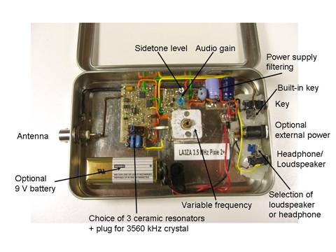
The Pixie 2 is this minimal transceiver which I and many others have played around with and had lots of fun with. My 80 m version is shown to the right, but right now it is very popular with some incredibly cheap Chinese ones on sale on Ebay and other places.
The Pixie 2 uses the versatile LM386 amplifier for its audio output. I have shown previously on this blog how its gain can be boosted and how it can implement a CW filter, and also how the muting can be improved. However, during transmission, the LM386 just sits there idle, although it can be used to amplify a sidetone from an external oscillator.
But I’m sure the old 70’s LM386 can do better than this. Despite its age, recently some pretty amazing uses of this chip have been demonstrated. It can be used as a regenerative receiver at least up to medium wave frequencies and it can also be used as an envelope detector/demodulator.
The LM386 challenge is this: Is is possible to implement a sidetone oscillator for the Pixie using only the LM386 with as few other components as possible? The output level needs to be controllable in order to make it comparable to that of the Pixie in the receiver mode.
The best data sheet for the LM386 seems to be the one for NJM386 from New Japan Radio Co. It is, as far as I know, the only one which shows the various muting circuits including the one using pin 7 which I have explored. It also shows the LM386 as an oscillator: both a sinusoidal and a square wave one.
In order for the LM386 to be useful as a sidetone oscillator, I believe that the oscillation must take place in the input circuitry. That seems to be the only way to ensure that the output doesn’t come out at a blasting full rail-to-rail swing as in the square wave oscillator example in the data sheet.
By the way, the data sheet referred to above is also the basis for the improved Spice model for the LM386 that just was developed. It came partly as a response to my complaint over how poor the present one was. Maybe the new Spice model, developed by EasyEDA, could help solve the LM386 challenge?
The LM386 Pixie challenge

The Pixie 2 is this minimal transceiver which I and many others have played around with and had lots of fun with. My 80 m version is shown below, but right now it is very popular with some incredibly cheap Chinese ones on sale on Ebay and other places.
The Pixie 2 uses the versatile LM386 amplifier for its audio output. I have shown previously on this blog how its gain can be boosted and how it can implement a CW filter, and also how the muting can be improved. However, during transmission, the LM386 just sits there idle, although it can be used to amplify a sidetone from an external oscillator.
But I’m sure the old 70’s LM386 can do better than that. Despite its age, recently some pretty amazing uses of this chip have been demonstrated. It can be used as a regenerative receiver at least up to medium wave frequencies and it can also be used as an envelope detector/demodulator.
The LM386 challenge is this: Is is possible to implement a sidetone oscillator for the Pixie using only the LM386 with as few other components as possible? The output level needs to be controllable in order to make it comparable to that of the Pixie in the receiver mode.
The best data sheet for the LM386 seems to be the one for NJM386 from New Japan Radio Co. It is, as far as I know, the only one which shows the various muting circuits including the one using pin 7 which I have explored. It also shows the LM386 as an oscillator: both a sinusoidal and a square wave one.
In order for the LM386 to be useful as a sidetone oscillator, I believe that the oscillation must take place in the input circuitry. That seems to be the only way to ensure that the output doesn’t come out at a blasting full rail-to-rail swing as in the square wave oscillator example in the data sheet.
By the way, the data sheet referred to above is also the basis for the improved Spice model for the LM386 that just was developed. It came partly as a response to my complaint over how poor the present one was. Maybe the new Spice model, developed by EasyEDA, could help solve the LM386 challenge?
Regenerative receiver based entirely on the LM386
I got a tip the other day that there is an interesting circuit over at the RadioBoards Forum where an LM386 IC is used as a regen receiver for the medium wave band. It is the user ‘Selenium’ who has come up with that circuit. I think it is quite an amazing application of this IC – so here it is:
 |
| LM386 as a medium wave regen receiver by user Selenium on RadioBoards Forum |
Interestingly, both the + and – inputs are tied together (pins 2 and 3). It is also quite unusual to connect pin 7 to anything but capacitors (for bypass or extra input as I have done), so that may change the bias of the input stage. Further, the smaller the impedance from pin 1 to ground, the larger the gain (here 10 uF in series with 1k).
If you want to read more about the regen circuit, go to the RadioBoards Forum here.
Regenerative receiver based entirely on the LM386
I got a tip the other day that there is an interesting circuit over at the RadioBoards Forum where an LM386 IC is used as a regen receiver for the medium wave band. It is the user ‘Selenium’ who has come up with that circuit. I think it is quite an amazing application of this IC – so here it is:
|
| LM386 as a medium wave regen receiver by user Selenium on RadioBoards Forum |
Interestingly, both the + and – inputs are tied together (pins 2 and 3). It is also quite unusual to connect pin 7 to anything but capacitors (for bypass or extra input as I have done), so that may change the bias of the input stage. Further, the smaller the impedance from pin 1 to ground, the larger the gain (here 10 uF in series with 1k for low frequencies and 100 pF for high frequencies).
If you want to read more about the regen circuit, go to the RadioBoards Forum here.
Another Pixie
Yet another variation on the Pixie arrived by email today from Sverre Holm in Norway who has LM386 mods to reduce BCI, provide mute and add sidetone.
See http://la3za.blogspot.no/2003/04/using-pin-7-of-lm386-to-reduce-bci-and.html .
This looks a very useful mod to this simplest of circuits. Sverre also added a much wider tuning range that helps to get contacts. Low power does not seem to be the main handicap.


