Posts Tagged ‘LF’
 VK4YB Lights Up West Coast On 630m
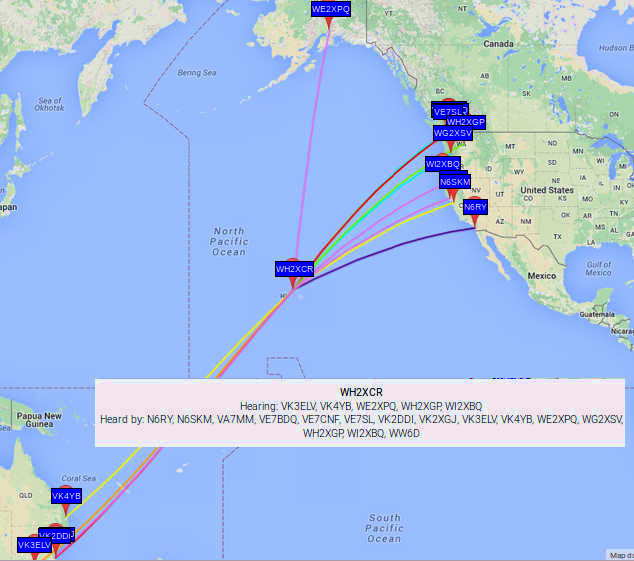 The past few weeks have seen many of the VK 630m WSPR stations making it into North America's west coast and points east. VK2DDI, VK2XGJ, VK3ELV and VK4YB have been the signals most often seen. Particularly dominant is the signal from Roger, VK4YB, the northern-most station, located in Moorina, Queensland, near the Pacific Ocean.
Roger's signal has been decoded locally by myself as well as VE7BDQ and VA7MM, creating excitement over the more normal nightly spots from the central states.
2016-04-13 11:10 VK4YB 0.475646 -28 QG62ku 5 VA7MM CN89og
2016-04-13 11:20 VK4YB 0.475647 -29 QG62ku 5 VA7MM CN89og
2016-04-13 11:28 VK4YB 0.475647 -28 QG62ku 5 VA7MM CN89og
2016-04-13 11:28 VK4YB 0.475644 -23 QG62ku 5 VE7BDQ CN89la
2016-04-13 11:36 VK4YB 0.475644 -26 QG62ku 5 VE7BDQ CN89la
2016-04-13 11:52 VK4YB 0.475643 -25 QG62ku 5 VE7BDQCN89la
2016-04-13 11:56 VK4YB 0.475643 -28 QG62ku 5 VE7BDQ CN89la
2016-04-07 08:54 VK4YB 0.475643 -25 QG62ku 5 VE7SL CN88iu
2016-04-07 09:36 VK4YB 0.475644 -29 QG62ku 5 VE7SL CN88iu
2016-04-07 10:08 VK4YB 0.475644 -29 QG62ku 5 VE7SL CN88iu
2016-04-07 10:18 VK4YB 0.475644 -29 QG62ku 5 VE7SL CN88iu
2016-04-07 11:04 VK4YB 0.475644 -29 QG62ku 5 VE7SL CN88iu
2016-04-13 11:06 VK4YB 0.475644 -24 QG62ku 5 VE7SL CN88iu
2016-04-13 11:10 VK4YB 0.475644 -23 QG62ku 5 VE7SL CN88iu
2016-04-13 11:20 VK4YB 0.475644 -23 QG62ku 5 VE7SL CN88iu
2016-04-13 11:28 VK4YB 0.475644 -28 QG62ku 5 VE7SL CN88iu
2016-04-13 11:32 VK4YB 0.475644 -25 QG62ku 5 VE7SL CN88iu
2016-04-13 11:52 VK4YB 0.475643 -18 QG62ku 5 VE7SL CN88iu
2016-04-13 11:56 VK4YB 0.475643 -22 QG62ku 5 VE7SL CN88iu
2016-04-13 12:16 VK4YB 0.475643 -27 QG62ku 5 VE7SL CN88iu
2016-04-13 12:28 VK4YB 0.475643 -26 QG62ku 5 VE7SL CN88iu
2016-04-13 12:32 VK4YB 0.475643 -25 QG62ku 5 VE7SL CN88iu
2016-04-13 12:54 VK4YB 0.475644 -24 QG62ku 5 VE7SL CN88iu
2016-04-13 12:58 VK4YB 0.475643 -24 QG62ku 5 VE7SL CN88iu
2016-04-13 13:10 VK4YB 0.475643 -25 QG62ku 5 VE7SL CN88iu
2016-04-13 13:24 VK4YB 0.475643 -27 QG62ku 5 VE7SL CN88iu
2016-04-13 13:28 VK4YB 0.475643 -27 QG62ku 5 VE7SL CN88iu
Roger has sent the following information to me regarding his well-planned system:
My antenna is serendipitous.
I am a complete novice on 630m. I only came on the band about 2 months ago at the request of a local friend, Peter, VK4QC. That is not quite true, because I was on the band once before, about a year ago and made one contact and then managed to burn out the front end of my Drake TR7, which I had roughly converted to 630m operation.
My QTH is atop of a stony ridge on 10 acres. The previous owner said there was some soil somewhere, but I haven't found it yet! Ground conductivity is very poor, I think. If you drive in two stakes about six inches apart, an ohmmeter says infinity. That's if you can drive in a stake. Because after the first quarter inch you hit shale rock. Interestingly the shale layers are at about 60 degrees to the horizontal. There are some quartz inclusions. Yes, I have tried crushing the quartz and panning it - no gold!
Getting back to my story, I needed to put up a 630m antenna in a hurry. The idea of winding a big loading coil with the rotatable inner coil was a bit daunting. And putting down ground radials or an earth mat was out of the question. So, using only some wire, string and a bow and arrow, this is what I came up with:
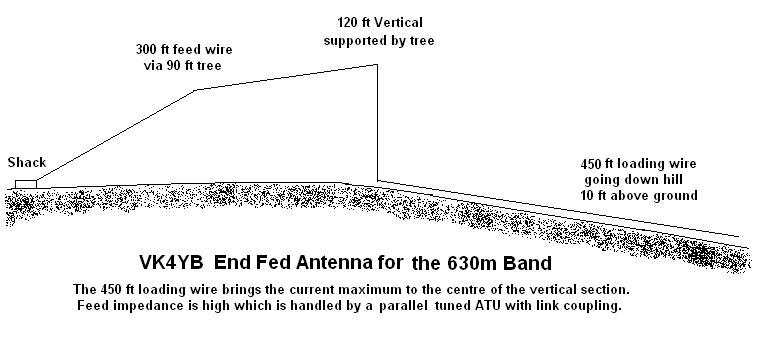
What is missing from that drawing is that the wire is running North-East to South-West, all in a straight line, with the shack at the North-East end. It is line-of-sight from the top of the vertical section to the Pacific ocean. I didn't put the direction on the original drawing because I didn't think it was important. I thought it was essentially a top-fed vertical and would therefore be omni-directional. Nothing could be further from the truth. Experience has shown that it is very directional. I have never had a single report from Japan, and yet my signal has peaked at -3 in Hawaii (about the same distance). Also VK3ELV, using a quarter wave near vertical, gets almost nightly reports from both Japan and Hawaii and at similar strengths. That would seem to indicate a front to side ratio of more than 20dB for my antenna, which is surely impossible?
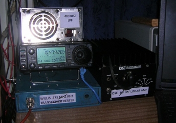
I estimate the feed point impedance is about 3000 ohms. The ATU has 48 turns on the secondary, tuned by fixed capacitors of 960 pF in parallel with a 500 pF variable which is about two thirds meshed. The primary is 5 turns fed by the transverter having a 50 ohm nominal output. The impedance at the top of the secondary should be near 5000 ohms, but the antenna feed wire is tapped about two thirds of the way up the secondary coil, which gives 1.03 : 1 SWR. The earthy end of the coil is connected to the mains earth and the metal work of the shed. I haven't tried terminating the far end. I did think about connecting it to the fence wire that runs round the property but I thought that might be a bit dangerous. There would be high voltage points in places. The transverter output is nominally 50 watts, but it is giving about 90 watts in reality.
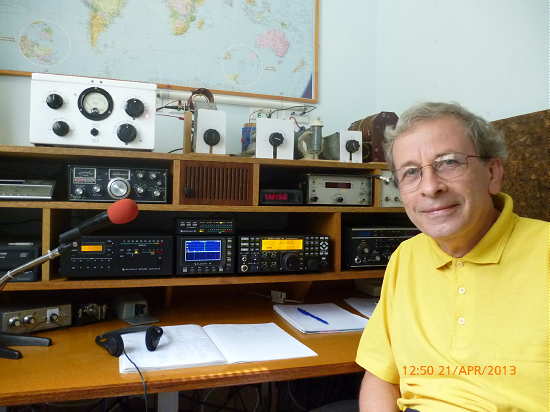 |
| Roger - VK4YB |
Like many on 630m, Roger is using an Elecraft K3 into a transverter to generate his 630m 90 watt signal. It is interesting to see the strength of Roger's signal here throughout the night but particularly during the 1152-1156Z time slot. His signal peaked at -18db, right at the level of audibility ... CW levels, but quickly dropped. Throughout the night however, his signal was easily within range of the capabilities of the two-way JT-9 WSPR QSO mode ... had either of us been seriously involved in a two-way JT-9 QSO attempt during that night, it would have been quick work I think.
John, VE7BDQ, has already managed to push his WSPR signal to VK on more than one occasion ... this from a typical, suburban backyard inverted-L. The possibilities are exciting, but will mean some middle-of-the-night vigilance!
As activity on 630m increases in both VK and VE, we are beginning to see more and more DX possibilities arising, particularly during the Spring and Fall equinox periods when this path seems to peak. As activity in Japan picks up, it is only a matter of time before some of them begin showing up in numbers here on the west coast, as the path to JA has always been reliable and somewhat less demanding than the path to down under. I suspect also, that as the present solar cycle draws down (and supposedly goes 'quiet'), 630m Trans-Pacific signals will grow even stronger,and on most other paths as well.
In view of the JT9 QSO possibilities, I think it is clear that I now need to seriously think about building a transverter, allowing me to at least be in 'ready-mode' for the coming 630m challenges ... hopefully for the next equinox.
Top Hats
 When it comes to discussion of 630m, the topic of antennas seems to top the list. One of the easiest ways to enjoy what 630m has to offer is to try and utilize a low band antenna that may already be in place. An 'inverted-L' for 80 or 160 can be readily bottom-loaded and with a few radials, can provide a good starting point ... but with a little additional work, its efficiency can be easily improved by expanding the top horizontal (top hat) section.
Jim, W5EST, has posted an interesting description of the pros and cons of the 'top hat' in a recent KB5NJD daily 630m report. Those thinking about getting on the band or those considering ways of improving their present antenna might find the information helpful.
Top Hat Advantages:
Higher EIRP comes from a more nearly uniform current distribution all the way up a TX vertical. https://en.wikipedia.org/wiki/T-antenna . But remember that adding top hat doesn’t help you if your license is subject to a legal limit EIRP that’s reached by your station already.
A vertical without a top hat has no current at its tip, meaning the upper part of a hatless vertical is inefficiently used. Average RF current for a hatless short vertical is only half what an RF ammeter shows at the antenna base. Top hat lets a shorter vertical antenna yield same total radiated power TRP by increasing its degree-amperes, as discussed March 31, this blog.
2 amperes of 630m RF base current in a 10° tall hatless short vertical can give 10 degree-amps (2 x ½ x 10°) and yield 15 degree-amps with an ample top hat. A top hat can increase average RF current by about a quarter to half, which could as much as double the TRP.
Top hat increases antenna system capacitance. You get more flexible QSY by decreasing the system Q. SWR increases rapidly as your frequency departs from antenna system resonance, see graph Feb. 10, this blog. With lower system Q the SWR doesn’t increase so rapidly. Then you can QSY temporarily a little way without retuning or by just retuning a little in the shack instead of outdoors at the ATU.
Decreased Q somewhat lowers antenna voltage KV from antenna base to top hat. On 630m Q = (2π 475)L/R by definition and Vantenna = 1.4 Q P / I < Vbreakdown. See Jan. 16, this blog.
Top hat wires can be symmetrically or asymmetrically positioned to give approximately similar capacitance whichever way. I’ve not modeled the effect of a top hat on the azimuth and elevation antenna patterns of an electrically short vertical. I don’t think the effect is very significant. But if you know a link or some better information about this, let us know.
If your radials have extended way beyond the extent of a small top hat high above, then providing longer top hat conductors above the radials can more efficiently utilize the radials. If the radials mostly go in one or two directions, then for highest antenna system capacitance the hat wires should extend in those directions to couple best with the radials. Your experience may suggest this last is not too important, especially if you have a perimeter conductor and/or several ground rods and your soil has favorable conductance.
Another top hat advantage is that top hat conductors are compatible with structural support and stabilization for the very top of an MF/LF vertical antenna. You get added degree-amperes–and steadying at the top to boot.
If the top hat slants upward, its system capacitance contribution is somewhat decreased compared to a top hat of same length horizontally, but the vertical slant contributes radiated power. Depending on the arrangement of antenna and trees on some properties, using a shorter vertical with an upwardly slanting asymmetrical top hat may make the antenna system both easier to guy and less obvious to neighbors.
Putting in a top hat or improving a top hat increases the degree-amperes of a short vertical mainly by distributing the same RF amperes more uniformly. Adding more radials and longer radials decreases the antenna system resistance and increases the degree-amperes of a short vertical mainly by increasing the RF amperes of antenna current itself.
Top Hat Disadvantages:
A top hat obviously requires outdoor work to construct or revise it. You may be able to simply increase your transmitter power TPO more conveniently than to do the outdoor work.
A top hat needs to extend more or less horizontally from the top of the vertical, although the angle is not too critical within +/-45°. Distant supports for the top hat at that top level may be unavailable or expensive and inconvenient to provide. If the top hat were attached to the vertical below the top of the vertical, the otherwise radiation-beneficial top segment of the vertical becomes mostly unused.
If the top hat slants quite steeply downward, its effect on system capacitance may be a wash– more capacitance by closer approach to the ground and less capacitance because same length top hat conductor extends less outward over the ground below. That defeats a reason for putting up a top hat in the first place.
Moreover, if the top hat slants steeply downward, then vertically downward RF current in the top hat cancels part of the radiation from the vertical antenna and at least partially defeats the improvement in vertical antenna current uniformity that the top hat is intended to confer.
A long top hat may not fit on the available real estate. Even if it fits, it may add to visibility as far as difficult neighbors are concerned.
Adding a top hat means you need to retune the ATU after the addition. But so does improving the radials or just about anything else you do.
Top hat conductors add more weight on a vertical than lighter-weight guying does. The weight of the top hat likely adds to the support demanded of the antenna base. If you put downward-slanting top hat conductors under tension at their far ends to keep them from drooping in the middle, then a lot of that tension will be imposed on the vertical too. That can produce a buckling force on the vertical which may call for additional guying halfway up the vertical.
Top hat conductors convey a declining but substantial RF current along their length. That involves I2R losses in the skin effect resistance of the top hat conductors. However, if your earth resistance is high or your radial/grounding system is not very elaborate, some loss in the top hat probably does not decrease the RF amperes of antenna base current very much at a given TPO compared to the improvement in radiation TRP that the top hat gives you.
If skin effect resistance losses in the top hat are significant compared other losses in the system, reducing top hat losses generally means more conductors or heavier conductors in the top hat. That translates to more weight for the whole system to support.
A top hat translates KV of antenna top voltage to its ends. If the top hat extends all the way to leaf cover of trees or shrubs, unexpected sparks might jump to them in quiet weather, or in windy weather, or sometime when such trees or shrubs grow nearer to the top hat end(s).
Generally top hat advantages outweigh their disadvantages so long as you plan intelligently. Please tell us your experiences with top hat advantages and disadvantages!”
 |
| A G3XDV LF top hat |
Jim often adds an interesting op-ed piece to the KB5NJD daily report and sifting back through the past few weeks will provide some great 630m 'food for thought' bed time reading!
630m To Down Under
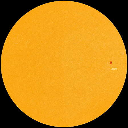 |
| Today's Sun courtesy: http://sdo.gsfc.nasa.gov/ |
With the sun remaining reasonably quiet over the past several days, a sudden spike in the geomagnetic field on Saturday afternoon saw a number of trans-Pacific spots showing up on 630m WSPR mode.
 |
| courtesy: http://wdc.kugi.kyoto-u.ac.jp/ |
 | |
| courtesy: https://www.google.ca/maps |
 |
| VK3ELV 630m |
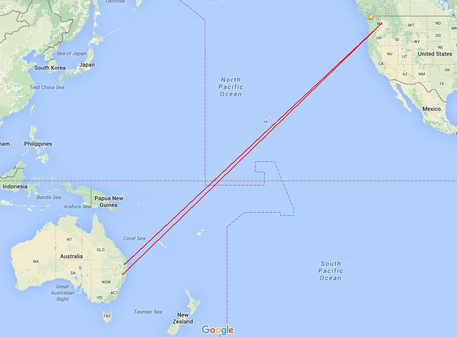 |
| courtesy: https://www.google.ca/maps |
Although VK3ELV's signal was right at the edge of WSPR decoding levels (-29db), it would only take a few more db to allow a two-way JT9 digital mode QSO to take place ... maybe something that will be possible in the coming years of solar minimum and much better LF/MF propagation. To be readable on CW would need an equivalent true power output increase of at least 16 times, requiring VK3ELV to run around 2,000 watts output!
Over the years I have seen ZL6QH a number of times on 2200m (QRSS CW mode) but this is my first reception of VK and, hopefully, not my last.
To keep up to date with overnight activities on 630m, visit the excellent site of KB5NJD. John posts a detailed daily summary of events. In addition, you will find some excellent resources to help you get involved in this part of the spectrum ... and remember, you don't need a big backyard or a big antenna to have fun on 630m.
ARRL Working For LF / MF Future

As the rollout of new LF and MF ham bands grows closer for U.S. amateurs, earlier this month, the ARRL requested the FCC to carefully consider the procedural requirements governing the advance notification of local electric authorities of their intended 630m / 2200m operation. The FCC had suggested that under certain circumstances (mainly the distance to the nearest PLC signal-carrying power lines), amateurs would be required to notify and co-operate with power authorities ... but it was all very vague and seemed to place the conditions under which operating authority would be granted into the hands of the power companies.
In what appears to be a preemptive move to head-off the (possibly) overly onerous and impossible roadblocks suggested by power company representatives, the ARRL filing states:
“ARRL does not object to such a notification requirement, provided that it is appropriately circumscribed, not overbroad in its applicability, and not overly burdensome for radio amateurs to comply with,” the League’s statement asserted.
In addition, the power authority Utility Telecom Council (UTC) has been notably silent on the issue ... slowing the process even further.
"The ARRL noted that comments filed by the Utilities Telecom Council (UTC) called for a system of “quasi-coordination” by radio amateurs before commencing operation on 2200 meters (135.7-137.8 kHz). In its remarks to the FCC, the ARRL pointed out, however, that the UTC has not volunteered any information with respect to how a notification process might work nor offered any PLC database information to the ARRL or to the amateur community so prospective users of the band could determine if their operation might be problematic."
The League took the opportunity to remind the FCC, once again, that the low ERP levels generated by amateurs operating on the new bands would have a low probability of creating any interference and further pointed out that PLC systems operating between 9 and 490 kHz are not subject to protection from licensed services.
The ARRL also indicated that any sort of blanket notification requirement prior to transmitting on 2200 or 630 meters “would be clear regulatory overkill,” and that utility companies should clearly be required to demonstrate how amateur operations would cause harmful interference to their PLC (unlicenced) operations.
It's good to see the ARRL still being proactive with regards to procuring these new frequency allotments on behalf of U.S. amateurs ... hopefully making implementation sooner rather than later. The entire ex parte filing can be read here as well as the ARRL's own news posting of the procedure here.
In the meantime, I'll make yet another call-to-arms to fellow Canadian amateurs, who already have these two new bands but aren't using them ... new activity from the western provinces would be especially welcome as there are a now a number of well-equipped stations in VE7 who would like to work you.
PAØRDT Miniwhip Shakedown Continues
Those of you that have been following the recent set of four YouTube videos posted in my recent PAØRDT Miniwhip Shakedown blog, regarding the care and feeding of the PAØRDT active e-probe antenna, may be interested in a fifth video in the series, posted by Mike in the U.K.
PAØRDT's recent modification of the isolating transformer, in the miniwhip coupling unit, provides much better immunity to common mode noise-coupling in the HF bands. Mike shows the installation and operation of the new unit along with some additional grounding out at the antenna.
Those of you that are looking for a possible solution to relatively good reception on LF or on the 630m band, might find the answer with a carefully thought out installation such as the one shown in Mike's video series.
Although living in the suburbs often means dealing with a lot of noise, particularly on LF / MF, Mike's system shows that excellent low noise reception is indeed possible. It is important to 'probe' your backyard with the antenna itself in order to find the quietest location for installation.
More information on the PAØRDT miniwhip and other low-noise LF / MF antennas may be found in previous blogs here.
An RF-Quiet Light Dimmer?

I admit it. I have an extraordinarily kind next door neighbour!
Ever since erecting a new, much bigger LF antenna several years ago, she has allowed me to run its large, three-wire 100' tophat, directly over the top of her house to a tree on the far edge of her property. As well, she removed her only light dimmer, knowing that it was creating a LOT of nasty RF 'hash' throughout the LF / MF spectrum, seriously degrading my LF reception. To hear the RF noise-signature of a typical light dimmer, listen here, on the ARRL's helpful page of 'household' RFI recordings ... that's just how it sounded here as well!
She recently did a major renovation, which included a new multi-light dining-room fixture and expressed to me a desire to be able to dim it ... oh-oh, I was definitely not looking forward to this.
I did a little web-research and soon learned that some of the most RF-quiet dimmers were being produced by Lutron. One model in particular, claimed to pay special attention to RF noise-filtering and that was the "Centurion", whose smallest model is a 600 watt-capable unit, with a large finned heatsink front plate ... model #C-600P-WH.
I decided to order one from the only dealer I could find in Vancouver that seemed to carry this line of dimmers. The cost was just a little over $40 Canadian (sells for about $25 in the U.S.A.) ... cheap enough if it would do the job!
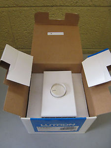
When the unit came in, I picked it up on my next ferry trip to the city and upon my return, installed it the following afternoon. Before doing the installation, I fired-up the receiving system, tuned to 300kHz, and with the baby monitor set up beside the speaker, took the portable monitor with me.
After installing the new dimmer, I turned on the baby monitor, held my breath ... and turned on the light fixture. Wow ... not a trace of hash could be heard! Adjusting the dimmer from high to low produced no difference in the noise level. I later did a more thorough bandscan and could find no evidence of RFI, on any frequency. The only RFI that I could detect was when placing my Sony ICF-2010 close to the actual dimmer. I was unable to detect any noise further than 6" away from the lights or the dimmer!
So it seems that this model can be highly recommended, for your own home or if you have a next door neighbour 'light-dimmer problem'.
PAØRDT E-Probe Improved VLF Noise Performance
 |
| courtesy: http://www.leeszuba.com/projects/ |
A recent blog posting of four videos showing the installation of a new (Roelof-made) PAØRDT active E-probe antenna revealed that there appeared to be a difference between his earlier model and his latest. It was noticed that the noise ingression levels were different between them, with one showing less noise on LF than on HF, while the other one behaved just the opposite. The newer PFU has the antenna ground isolated from the receiver's ground while the older one does not. Noise coupling, with the new one was higher on HF and lower on LF, which was just the opposite of what was noted with the older unit with its un-isolated ground ... overall LF performance over the newer system was deemed to be better as seen in the final video here.
The only difference seemed to be in the coupling isolation transformer, used in the power feed unit (PFU), likely similar to the one shown at the bottom of this page.
Roleof's transformers are wound on a Magnetics 0W40705TC toroid, whose high mu ferrite has an Al value of ~8350. I mentioned to Roelof that is seemed unusual that the noise levels would be greater on HF than on LF, with the new transformer, as usually it's the other way around when it comes to noise. The changes noted in the video lead to further transformer testing by Roelof, who indicated :
The isolating transformer consists of two bifilar windings on a high mu core. My guess is that the interwinding capacitance spoils the isolation at HF. I have just tested an isolating transformer with two separate windings opposite each other on the tiny core. Sure enough, this solves the feedthrough at HF and VLF performance is not impaired at all.
I have never given this a second thought as I believed it was specific for my location. Never too old to learn!
Further testing indicated:
I have evaluated both transformer types on my spectrum analyser and found the following.
The current transformer with a twisted bifilar winding is a
transmission line transformer. In a 50 ohm system, it covers 4 kHz (!) to 200 MHz at -3dB. Which is very good.
The new one, using the same core and separate windings is an other
story. It covers just 4 kHz to 8 MHz at -3dB. At 30 MHz the loss is
13 dB. So, excellent for VLF / LF/ MF, it won't do for upper HF.
I will try other core material and see if a feasible compromise is
possible.
To be continued.
further...
I first tried a FT-37-43 toroid with 10 turns for each winding.
This core is suitable for higher frequencies and I expected it to
work better than my high mu (8300) cores.
Nope, it was far worse and at 30 MHz the loss was already > 20 dB.
I reverted back to my magical cores and reduced the number of turns
to 3. This yielded a nice bandwidth (-3dB)from 50 kHz to 50 MHz.
Used in the mini-whip interface, there is no more a difference
between shared grounds and isolated grounds on either VLF / LF or
HF.
Though the lower -3dB point is at 50 kHz, I still have excellent
reception of the Russian Alpha stations between 10 and 15 kHz.
It looks like this transformer is an excellent compromise for this
purpose.
I have often found that in practice, high mu cores are excellent for
wideband transmission line transformers. They are good for
traditional rf transformers as well!
and:
I just have tested a binocular core, the BN-73-202, available from
W8DIZ.
With two windings of two turns each of insulated hook up wire (to
keep interwinding capacitance low), gives a transformer from 80 kHz
to over 100 MHz. In practice reception down to 10 kHz is still
excellent.
There is no difference between isolated or common grounds either.
The coupling with this binocular core is a little better than with a
toroid. At LF / MW, I don't find any loss at all.
The FT-50-75 will do fine with two windings of 4 turns each.
I have some FT-50-77 cores at hand and will see how they work out.
I am surprised at the wide bandwidth that can be achieved.
and:
I have been testing a FT-50-77 ferrite toroid for use as wideband
isolation transformer.
Three turns on the Magnetics (aka magical) cores, give an inductance
of 60 uH. Used as a wideband Isolation transformer, the -3dB
bandwidth ranges from 80 kHz to 50 MHz.
For about the same inductance, the FT-50-77 core needs 6 windings.
Used as wideband isolation transformer, the lower - 3dB point is 100
kHz, the upper is 12 MHz. At 30 MHz the loss is already 8.5 dB.
Though not suitable as wideband isolating transformer, it still can
be used for the range 100 kHz - 3 MHz.
It looks that for good wideband performance the Al value must be >
5000 and the number of turns should be =< 3.
Interesting stuff and the best thing is that it has really lowered
my noise floor!
A summary posting to the RSGB's LF reflector indicates that the new transformer scheme is providing quieter VLF reception and good performance up to 200MHz
For years, I have been using a rf - isolating transformer to
separate antenna and receiver ground.
This is a home made transmission line transformer, consisting of 11
bifilar turns on a small high mu toroid (AL=8300). The inductance is
1.2 mH. The measured -3dB bandwidth in a 50 ohm system covers 4 kHz
- 200 MHz.
It appeared that the isolation was not perfect, due to the
inter-winding capacitance. I have made a new transformer on the same
core with two windings of each tree turns. The windings are opposite
each other on the core. The bandwidth is now 45 kHz - 50 MHz. The
loss is 1.3 dB.
Despite the raise in the lower -3dB point, reception at VLF is much
improved due to lower noise ingress. See attachment.
The screen runs from 1 kHz - 13 kHz. At the right hand the dashes
from the Russian Alpha system can be seen. The white band is with
common ground. Harmonics of the 50 Hz mains can be easily spotted.
In reality the picture will be better,as the sensitivity of the
PERSEUS drops considerable below 10 kHz.
The level of interference on 380 kHz caused by a plasma TV in the
neighbourhood is also much reduced.

An excellent video demonstrating the dramatic effects of isolating the ground in the e-probe antenna system on LF was posted today by PY3CRX. Marcus used the Magnetics hi-mu core with 5 + 5 turns (~ 390 + 390 uh).
For those not having access to the Magnetics material, it looks like the BN-73-202 binocular core is a good performer, from 10kHz - 100MHz. The FT-75 and 77 material also fair well but with differing bandwidths. Cores are available from Amidon as well as from W8DIZ's Kits & Parts.


