Posts Tagged ‘Electronics’
 DIY Magnetic Loop Antenna – Part 1
Do you live in a neighborhood with a restrictive antenna policy and despair of having a useful HF antenna?
Can you solder or know someone who can?
A magnetic loop antenna may be the answer and they are not as difficult to build as you might think. Like getting on the air for the first time or taking your license exam there is a certain amount of uncertainty when you first approach magnetic loop antennas, there are a few new ideas to grasp. However, thanks to other hams like Steve AA5TB there are tried and tested designs, calculators & building methods that are known to work and that you can follow.
 At the heart of every radio and MLA (Magnetic Loop Antenna) is the resonant circuit. The combination of an inductor (a wire has inductance, but a coil of wire has more) and a capacitor (two conductors separated by an insulator) in a circuit will resonate or ‘ring’ at a certain frequency. Sound vibrations at a certain frequency can cause a piano string to vibrate in sympathy and a vibration of the correct radio frequency will cause a resonant circuit to electrically vibrate in sympathy.
Since there is no such thing as a free lunch, the sacrifice you make with a MLA is that it needs to be re-tuned whenever you change frequency on your transceiver. The frequency range over which it is resonant is very small, typically only a few hundred kilohertz at the most.
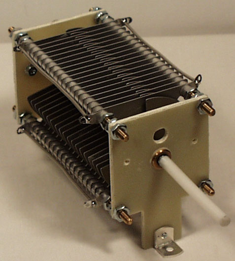
The materials you can get your hands on is going to decide the capabilities of your MLA. Ideally you’ll have a loop made from a conductor with very low resistance (usually copper) and a capacitor that can handle high voltages. A variable capacitor is required if you want to use your antenna on multiple frequencies but you can use or make a fixed capacitor if you operate on one frequency, for Eg PSK31.
A MLA calculator like the Excel spreadsheet from Steve AA5TB or this web page from 66pacific.com will help you to decide what size components you’ll need to make your antenna.
The four pieces of information required are:
- What frequency or frequencies do you wish to transmit on?
- How large do you want the loop to be (It should have a circumference less than 10% of the design frequency wavelength, both calculators help you figure this out)
- The diameter of your conductor (Three quarter inch (0.75 inch) copper pipe is a good start)
- How much power you want to use (The voltage across the capacitor is proportional to the input power to the MLA)
 A MLA of a certain circumference will be more or less efficient based on the frequency you transmit at. It is worth changing the loop size in the calculator to get the best efficiency possible in your favorite band.
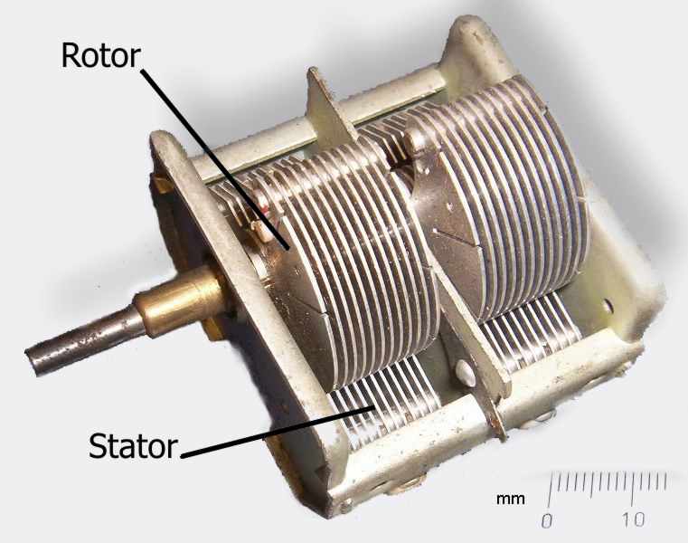
Now I understand – Phase Locked Loops
Every now and then I come across great books or videos that explain a concept in such a way that it becomes immediately obvious what is going on. I’m a great believer in learning by demonstration or even better, learning by doing.
I came across another explanatory video recently that I thought was too good to keep to myself. It covers a topic that was a complete mystery to me: Phase Locked Loops. We utilize them in almost every modern transmitter and receiver yet most people I have talked to view them as a black box that, fortunately, does its job well and usually without interruption.
The video below does a good job on opening the black box and showing just what makes phase locked loops … well, lock.
Hellschreiber and microprocessors – Bridging more than 80 years
ZL1HIT (Bryan Rentoul) has bridged a gap of more than 80 years by combining the text transmission system developed by Rudolf Hell in the late 1920’s with current microprocessor technology.
| A sample of received Hellschreiber test from Bryan’s beacon |
Hellschreiber sends a line of text as a series of vertical columns. Each column is broken down vertically into a series of pixels, normally using a 7 by 7 pixel grid to represent characters. The data for a line is then sent as a series of on-off signals to the receiver, using a variety of formats depending on the medium, but normally at a rate of 112.5 baud.
This process was historically accomplished with mechanical equipment but there are very few examples of this equipment still in operation and it is now sent and received by computer. Hellschreiber is very tolerant of noise and interference and requires only simple transmitters and receivers to work effectively.
 |
| German Hellschreiber unit in operation |
With a microprocessor generating the digital on-off signals a simple crystal oscillator transmitter can be used to form a beacon station, one that transmits a call sign and perhaps some other information over and over. Changing the transmitted message is as simple as reprogramming the microprocessor or having it respond to a connected input, for Eg. A thermometer, light sensor, switch, etc.
Receiving the signal and decoding requires a radio receiver capable of CW reception and a computer running any of several free software packages like FLdigi or Digital Master 780.
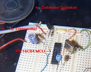 |
| The ZL1HIT beacon using a PIC microprocessor and a simple crystal oscillator transmitter. |
For more information and the PIC microprocessor source code please visit the web page of Bryan Rentoul here : ZL1HIT Hellschreiber / PIC Beacon
AmateurLogic.TV 33: One Jam Packed Show
George visits the Twit.tv studios and interviews Randy Hall, K7AGE. Tommy visits the Huntsville Hamfest. Jim builds an Audio Isolation Interface. Peter shows us the DATV QSO Party.
State of Electronics documentary
Karl Von Moller has been putting together a documentary called ‘State of Electronics – A discussion on the electronics industry in Australia’. This looks like a fascinating and thorough look at the electronics industry in one country. Although focussed on Australia much of the content and discussion will be recognizable and similar to other countries. The final version has not been released yet but it looks like it will be great viewing when it is. Seems it is growing to three parts. I’m looking forward to seeing the finished documentary.
Interesting point to note is the documentary has been filmed using a Canon D5 MarkII digital SLR.
Below is the trailer followed by the ‘roll call’ of people who appear in the documentary.


![]()
Learning electronics with the aid of the Internet

You have to learn electronics by building circuits. However, it can be very intimidating to get started and once you have some familiarity you may need further guidance, especially in the art of circuit design. Last week I watched three excellent tutorial videos which show there are some who are putting excellent material on the Web to help others further their learning of electronics. Here are the three.
First video covers some basic, but necessary understanding of multimeters and their use. Essential knowledge for beginners. This is by Colin Cunningham of Makezine.com and part of his ongoing electronics video posts at Make magazine’s website.
The next one steps it up quite a lot in detail but it is Dave Jones of the EEVblog showing how a component can be selected by a designer for a circuit, in this case for a DC-DC booster. It a long video, but shows how to use online catalogues, conduct parametric searches as well as the essential examination of component datasheets. Well worth watching carefully.
FInally, what looks like a new video podcast series from component supplier Element 14 and Jeri Ellsworth. In this video Jeri designs a circuit for some music playing installation art, that is triggered by motion detected by a PIR. This is a great tutorial video and I look forward to seeing more of these. The link to the video is here.
The latest good news seems to be that today it was announced that Jeri is joining Element14′s “Ask an Expert” panel.


![]()
Showing Brownies simple electronics

(Copyright V Steele)
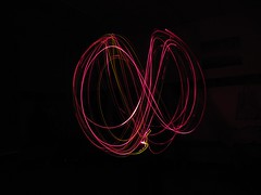
Ginny, my wife, is a one of a group of leaders for a Brownie pack in a nearby village. Last week we showed the Brownies some simple electronics and they had some fun with a really simple circuit.
We had them put a number of LEDs onto a 3V button cell, rather like a LED throwies but without the magnet. Once they had an arrangement of three or four LEDs on a cell Ginny took photographs of them in a darkened room as they waved the LEDs around. Taking a photograph on a slow file speed setting (ISO 80) and over a relatively long period (15 s) the Brownies created some great art by ‘painting with light’. As well as the example above, a small selection is shown below.


(All photographs copyright V Steele)
There was about 22 or so Brownies and we had them work on an LED ‘circuit’ in pairs. They really enjoyed the fun of arranging the LEDs and working out which way around to place them. However, I think they had the most fun with the ‘drawing with light’.
While some were involved with the photography I showed others the fun that could be had with electronics and how circuits could make things work. To do that I showed them how I could not light up an ultra-bright LED with a used 1.5V battery on its own. But, when I used a few components, connected into a Joule thief circuit, then the LED would light up brightly with the 1.5V battery. I also had some plastic optical fibre too and they had fun watching light bending around corners.
We kept the exercise simple and very visual and they all seemed to enjoy it.
If you want to make your own Joule thief you may find the Make magazine podcast below interesting and useful to watch.


![]()


