Posts Tagged ‘Electronics’
 Surface mount soldering
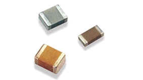
If, like me, you have had an irrational fear of surface mount devices for some time, you will be glad to know its not as bad as you may think. I recently started working with SMD and while I suffer from shaky hands and have poor eyesight, its actually quite a methodical process and not as fiddly as you would think.
I created a 2 part video on SMD soldering using a hot air (reflow) station and using solder paste. In this video I created a QRP dummy load which is a great introduction into Surface Mount Components and at a great price of £5.95 available from Kanga Products
Acorn II – Buildathon instructions
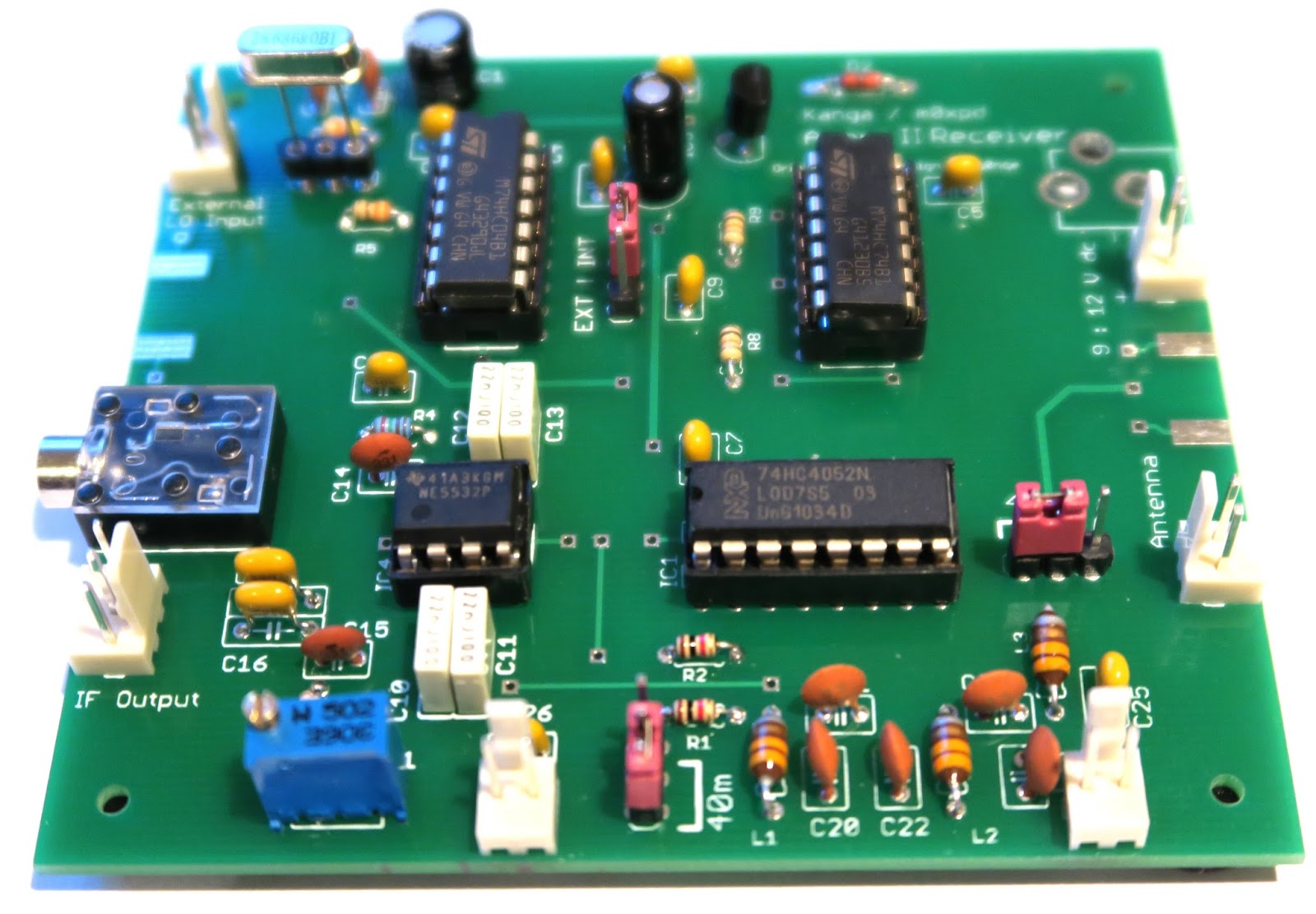
For those who have not seen the Arcorn II SDR kit, you can now purchase the complete kit for just £29.95 from www.kanga-products.co.uk The kit is an excellent entry into SDR receivers and we will be featuring this kit as a a part of the 2015 buildathon at the RSGB convention.
To aide the construction, I have created a set of instructions that may help with anyone who is building this little kit. You can download the PDF here, There are significantly more pages than the Kanga instructions, but for a group construction project we find that lots of space and easy to follow instructions are a great help.
And if you haven’t seen the construction video – here it is again.
Acorn II – Buildathon instructions
For those who have not seen the Arcorn II SDR kit, you can now purchase the complete kit for just £29.95 from www.kanga-products.co.uk The kit is an excellent entry into SDR receivers and we will be featuring this kit as a a part of the 2015 buildathon at the RSGB convention.
To aide the construction, I have created a set of instructions that may help with anyone who is building this little kit. You can download the PDF here, There are significantly more pages than the Kanga instructions, but for a group construction project we find that lots of space and easy to follow instructions are a great help.
And if you haven’t seen the construction video – here it is again.
Arduino Morse Tutor – Update
Its quite humbling really. Ive had this blog now for a number of years. I’ve always had a bit of a love/hate relationship with it. I love the concept of sharing my experiences, failures and successes with who ever stumbles across the blog. But mostly only a couple of entries get found and commented on. Namely my MQ26SR antenna posts are the most popular entries on this blog and I get about 1 email a month asking very specific questions.
That all changed this week. With the addition of my latest Arduino project. All of a sudden and quite literally overnight – the traffic to this blog skyrocketed. My inbox was awash of emails asking questions, my twitter feed was stacked with retweets and favorites of this circuit. I seem to have struck a chord with many folks who, like me, were looking for a Morse Tutor, but don’t want to sit in front of a PC all day.
I’ve had some really wonderful feedback. I have been offered Crowd funding, beta testers and asked if I can supply more information. So I hope this entry can help with my plans for my Morse Tutor version 2, So here are some headlines for you all.
- I am making a kit. I have this in hand and a PCB design is on the screen right now.
- This will be launched as soon as I have figured out some minor gremlins.
- There will be added functionality. And some really cool features too – watch this space.
- The Sketch I have created so far is only a fraction of what is on offer. (plus also a lot of fixes have been included in the Version 2 build)
- Below are 2 drawings – 1 Schematic, 1 Breadboard. This will support Version 1.01 of the code.
Version 2 will include an Audio Amp, an SD card and proper switching logic (either a rotary encoder, or latch chip) four new modes of training and all ready as either a pre assembled kit or kit of parts for you to build & box yourself. And trust me on this, it wont be expensive either.
Arduino Morse Tutor

In a recent conversation with my good friend Lewis, we started discussing Morse code, training and the old equipment that was used to educate and teach the code to newcomers. In particular we discussed the old Datong D70 practice oscillators. Lewis carried on the tell me that his Datong like so many others started sending odd illegal characters and essentially rendered the kit useless. Of course you could whip of the lid and replace the logic chips, but I thought of recreating the Datong functionality in a new Arduino sketch.
So here is a breakdown of what the Datong offered:
- Either Mixed, letter or number combinations
- Groups of 5 characters
- Variable speed ( up to 37.5 word per minute)
- Variable character spacing (up to 4 seconds)
The Datong also allowed you to connect a telegraph key, and your headphones. But for now I will focus on the code generation element of the project.
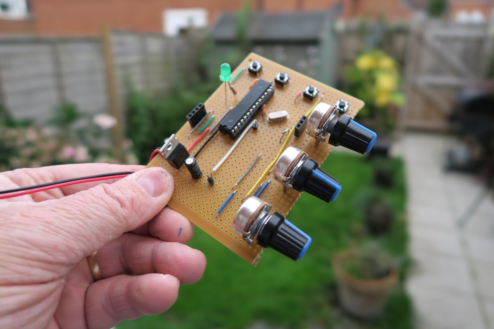
The finished project has just a handful of components and can easily be created on a breadboard, or indeed if you have an old broken Datong you can reuse the box and panel to really replicate the old kit. The complete project includes 3 variable resistors (1K LIN) for Character speed, gap and volume. It also needs a 3 way switch to select the mode.
The Arduino I’m using is the UNO. Arguably the most popular Arduino on the market, but I have also tried the sketch on a Nano and it works fine – just some customisation of pin assignments is all that is needed.
On start up the Arduino checks to see which switch is LOW – it also saves the current mode and checks if the saved mode is the same as the current selected switch. If this is different, then the Arduino has had a change in the mode selection and resets.
When generating the tones, the Arduino randomly selects a character from an array. With that chosen letter – it calls a function and plays the corresponding tone functions. 2 functions exist as a DIT and a DAH.
The rest of the functions are dedicated to allowing the speed and gap to alter and also displaying the results on the LCD panel (completely optional).
Here is a short video of the kit working, and a link to the source code.
Arduino Morse Tutor
In a recent conversation with my good friend Lewis, we started discussing Morse code, training and the old equipment that was used to educate and teach the code to newcomers. In particular we discussed the old Datong D70 practice oscillators. Lewis carried on the tell me that his Datong like so many others started sending odd illegal characters and essentially rendered the kit useless. Of course you could whip of the lid and replace the logic chips, but I thought of recreating the Datong functionality in a new Arduino sketch.
So here is a breakdown of what the Datong offered:
- Either Mixed, letter or number combinations
- Groups of 5 characters
- Variable speed ( up to 37.5 word per minute)
- Variable character spacing (up to 4 seconds)
The Datong also allowed you to connect a telegraph key, and your headphones. But for now I will focus on the code generation element of the project.
The finished project has just a handful of components and can easily be created on a breadboard, or indeed if you have an old broken Datong you can reuse the box and panel to really replicate the old kit. The complete project includes 3 variable resistors (1K LIN) for Character speed, gap and volume. It also needs a 3 way switch to select the mode.
The Arduino I’m using is the UNO. Arguably the most popular Arduino on the market, but I have also tried the sketch on a Nano and it works fine – just some customisation of pin assignments is all that is needed.
On start up the Arduino checks to see which switch is LOW – it also saves the current mode and checks if the saved mode is the same as the current selected switch. If this is different, then the Arduino has had a change in the mode selection and resets.
When generating the tones, the Arduino randomly selects a character from an array. With that chosen letter – it calls a function and plays the corresponding tone functions. 2 functions exist as a DIT and a DAH.
The rest of the functions are dedicated to allowing the speed and gap to alter and also displaying the results on the LCD panel (completely optional).
Here is a short video of the kit working, and a link to the source code.


