Posts Tagged ‘Elecraft mini-module kit’
 Making use of Elecraft Mini-module Kits
Connecting the bits and bobs
I have enjoyed building Elecraft Mini-Module kits. Now to put them to use...
 |
| Elecraft Mini-Module Kits |
What to do?
I built the kits as part of my learning adventure and to improve my soldering skills. It's also helped me learn to follow instructions better (my wife says I need to work on learning to follow instructions). But ultimately these modules are intended to be useful, and in my case they work nicely to when operating my old Ten-Tec Century/21.
My Ten Tec Century/21 is a 1970s CW-only, low(ish) power rig originally intended for Novice license holders of the time. It has no RF output meter or SWR meter. It has poor filtering/selectivity compared to modern radios and its analog tuning dial is a bit vague so you generally only know your frequency within 5 kHz.
The mini-module kits prove useful. I employ the W1 Wattmeter to determine my power output and SWR; the CP1 directional coupler is used to send a 20db attenuated signal to a frequency counter to determine operating frequency, and the AF1 Audio Filter makes operating near adjacent CW signals more pleasant by providing a narrow audio-band-pass filter. The result signal can be transmitted through a LDG tuner into the BL2 switchable balun connected to my attic Doublet.
Bring out your cables
All these independent modules need to be connected, so tying the bits and bobs together requires a few coax jumpers to route the RF around:
- UHF to BNC from the radio to the W1 Power meter
- BNC to BNC From the W1 Power meter to the CP1 coupler
- BNC to UHF From the CP1 coupler J1 input to switched T1 output to frequency counter
- BNC to UHF From the CP1 coupler J2 output to the tuner
And other cables:
- Serial cable from the W1 Power meter to the computer
- 12v power cables for the W1 and AF1 (unless I want to use 9V batteries)
- Audio cable from the TenTec C21 to the AF1
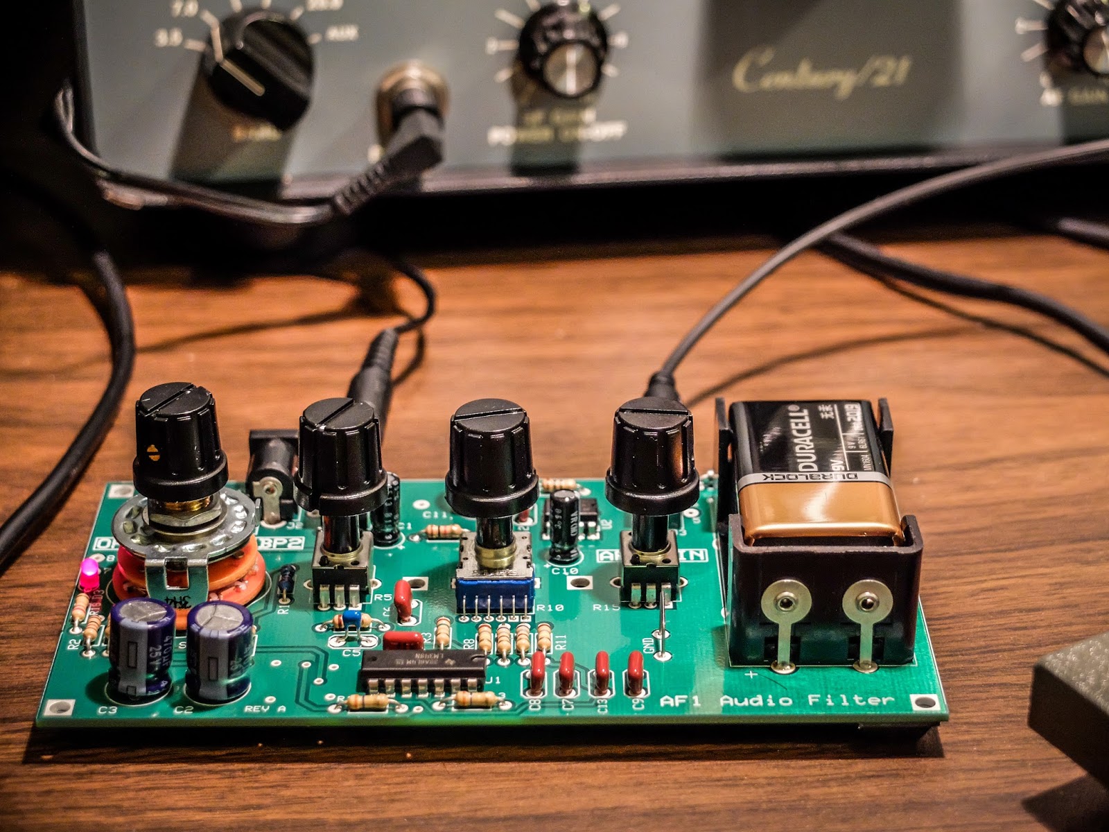 |
| AF1 Audio Filter making crowded band operations pleasurable |
 |
| CP1 Directional Coupler sending off 20dB attenuated signal to the frequency counter |
 |
| Frequency Counter fed by the CP1 directional coupler. |
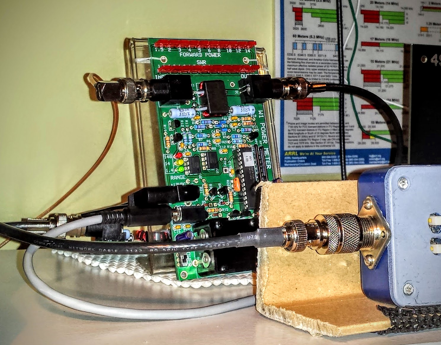 |
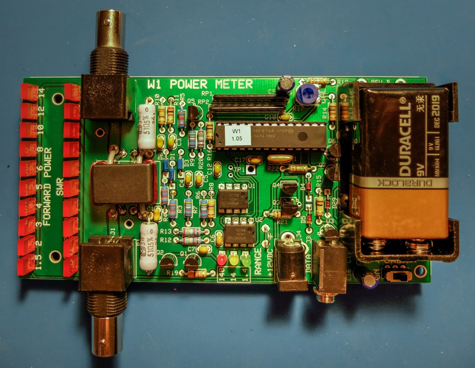
| W1 Power Meter sending its measurement off to the computer |
W1 Power Meter Output to Computer
The W1 has a serial output to a PC for use with the Elecraft W1 software. The software can both configure the meter and display more detail than can be determined from the LEDs. Source code is supplied and the command set is documented so it would be easy to write your own software for this.
The W1 power meter LEDs give you relatively discrete output information for the lower two ranges (0.1w to 1.4w) and (1.5w to 14w). But in the high range (over 14w) the LEDs are only displaying 10 watt intervals. For instance in the high range, when the second LED is lit you don't know if your operating just 20 watts or 29 watts. It won't trip the next LED until it crosses the 10 watt boundary in the high range so it can be useful to look at the measurement on the computer if you are operating QRO. I'm not complaining. I understand that the meter is primarily intended as a QRP meter and for QRP power (less than 15 watts) it offers plenty of information.
Here I brought the TenTec Century/21 up to nearly full input drive (55-60 watts) to see what it could output. The rig probably had a few more watts left in there but I didn't want to push it because I haven't gotten around to replacing some of the out of spec components in the internal power supply. I normally use this radio under 10 watts (I look for about 30 watts input on the drive meter) but I was curious to see what the old girl could do since I had the meter hooked up to the computer display.
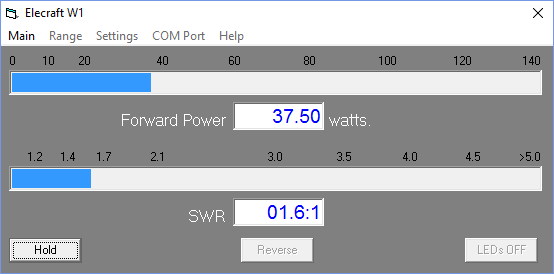 |
| Measuring maximum RF output from the Ten Tec Century/21 |
Nits and Quibbles
My antenna's native SWR at 15m (~21.08MHz) is around 2.5 so it requires tuning (impedance matching). After my LDG auto tuner spends a ridiculous amount of time trying to find a match it settles at 1.7 SWR according to the W1 Wattmeter, while the indication on the Autotuner is that it believes the SWR is 1.5 or better, while the radio on the other side of the W1 meter sees a SWR over 2.5. I only see this behavior on 15m so I think there is some strange impedance reaction occurring in the W1 wattmeter that is changing the reactance on the jumper to the radio. I've tried a few different jumpers, swapping jumpers, etc. But it always presents an abnormally high SWR to the radio at 15m. Now when I transmit into a dummy load I don't see this behavior, so it is some combination of SWR / reactance present at W1 that causes a impedance mismatch downstream toward the radio. I have more investigating to do but for now I am choosing to not use the W1 Wattmeter in-line when operating on 15m.
The CP1 directional coupler is not entirely transparent and raises the SWR by a bit as signal passes through it. You would expect there to be losses according to the -20 db taps (one forward and one reverse). This should work out to about 0.08% loss but I wouldn't expect it to raise the SWR. It adds about 0.1 to your SWR and occurs even if the forward and reverse couplers are switched "off" and shunt their respective loads to the on-board 50 ohm resistors. I'm unsure what accounts for that slight SWR bump but be aware that CP1 contributes some very small losses.
Summary
So the Elecraft Mini-modules are fun to build; and with enough jumper cables, can be combined for experiments and general augmentation of other equipment in your shack. So go out there, build some kits and experiment. It's a rewarding experience.
I'm trying to decide what I'm going to build next.
That's all for now...
So lower your power and raise your expectations
73/72
Richard, N4PBQ
I’ve Got the Power
Elecraft W1 Power Meter
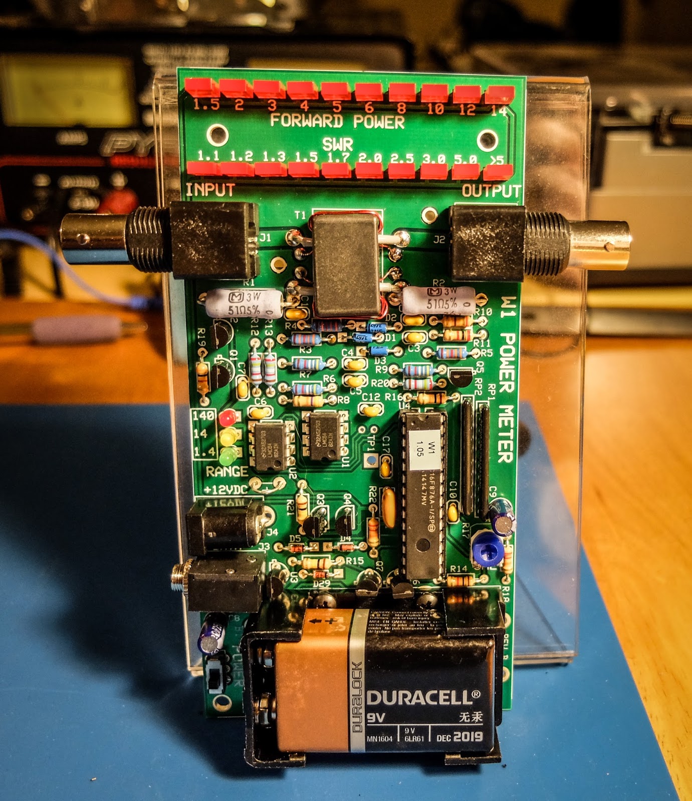
The Elecraft W1 is another fine mini-module kit from Elecraft. It is an auto-ranging power meter measuring as little as 150mw up to 140w. The 150 milliwatt to 1.4 watt range is an especially nice feature for QRP'ers.
 |
| Elecraft W1 Power Meter |
Building
I am new to building kits. My first kit was from 4-State QRP (Regen Receiver). This is my 4th Elecraft kit. The instructions are very detailed and easy to follow and I especially like that they give you the resistor color and capacitor identification right there in the instructions without having to refer to a data sheet somewhere else in the documentation.
All the parts come in a single bag so there is a bit of sorting that you need to do when you receive it. I use a big egg carton to sort and inventory the parts so that I can find them more easily.
This kit was a bit more involved than the other kits I've built from Elecraft. It has a binocular toroid which is fiddly to wind, 3 ICs and a couple of resistor packs. Lots of soldering. The most tedious parts to solder are the tiny transistors. Those solder pads are really close together for someone new to soldering like me, but I took my time and everything turned out ok. I worked on this kit a little at a time over 3 nights. If you can follow instructions and have a steady hand you should be fine.
The kit has some ESD sensitive parts so you'll want to be able to properly ground yourself and your equipment. Make sure your soldering iron is ESD safe and that you are grounded.
Lastly, final calibration is performed using just a multi-meter.
Build options
The meter can be built in a number of different configurations depending on how you plan to use it. The battery holder and BNC connectors can be installed on the top or bottom of the board and the BNC connectors can even be oriented vertically on the back side of the board. If you plan to use it in an enclosure give some thought to the location of the battery holder and BNC connectors before you get to that part of the build.
I plan to use some stand-offs to mount it to the front of an acrylic photo frame that I already had.
 |
| An acrylic-angled photo frame can make a homebrew stand |
Operation
The meter can operate from a 9V battery or from an external power supply via the barrel connector on the side. There is a small power switch at the bottom left of the board.
The top row of LEDs indicate power for a given range. The 3 LEDs mid way down the board to the left indicate the current power range. The range can be automatic or set via a command through the serial interface.
The ranges are:
- 150 milliwatts to 1.4 watts -- Green LED
- 1.5 watts to 14 watts -- Yellow LED
- 15 watts to 140 watts -- Red LED
Computer interface
There is a 1/8" stereo jack below the power connector that provides a serial interface to a computer. There is a command set for interacting with the meter as well as a sample application available on Elecraft's site that allows a number of settings to be modified such as peak hold and saved to the meter.Elecraft sells a $15 serial interface cable kit. What they don't tell you is that it has a DB-9 connector rather than a USB connector. I don't even have a computer with a DB-9 serial port so buyer beware. You may want to skip their kit and build your own. I happened to already have a DB-9 to USB converter but I'd preferred their kit to provide a USB connector.
Demonstration
Photos
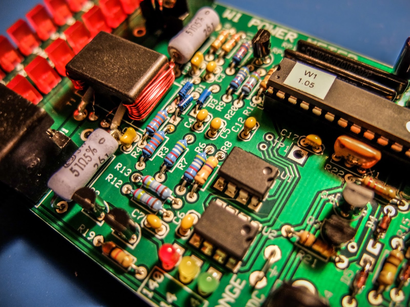 |
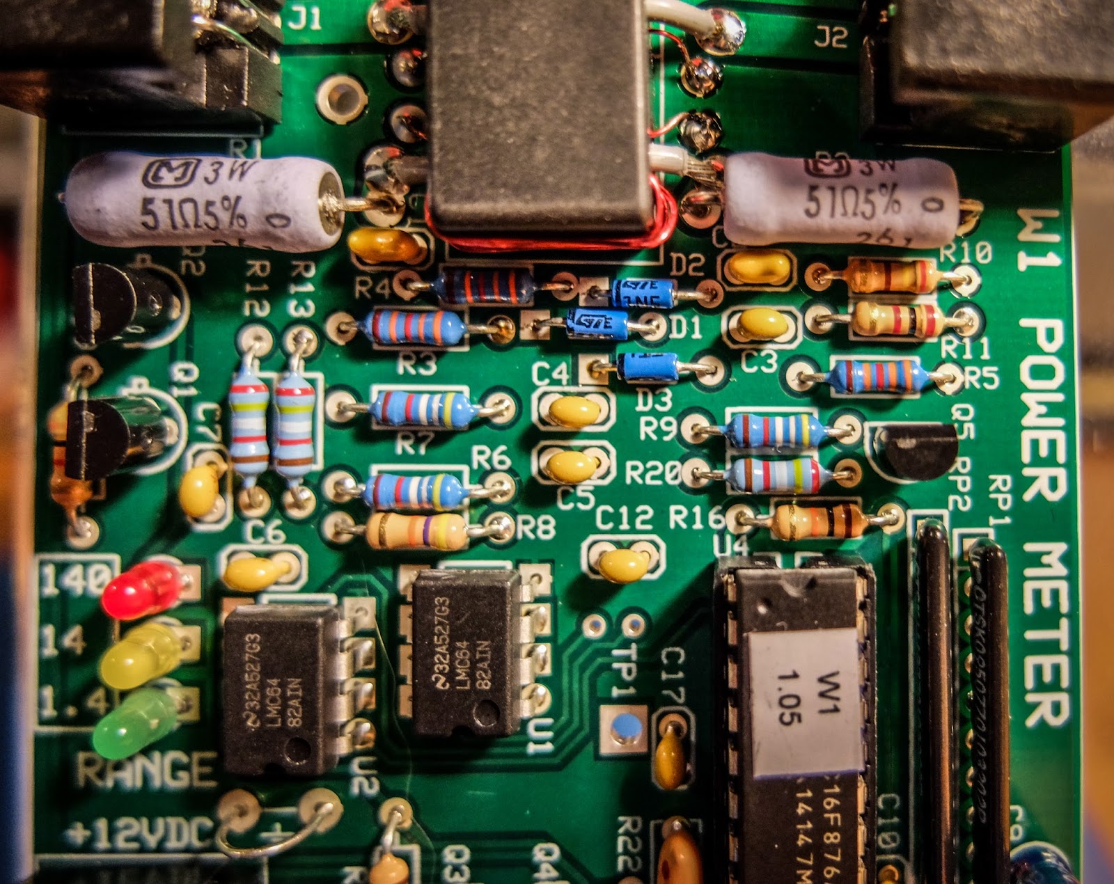
| 3 ICs to solder and toroid winding... lots of fun |
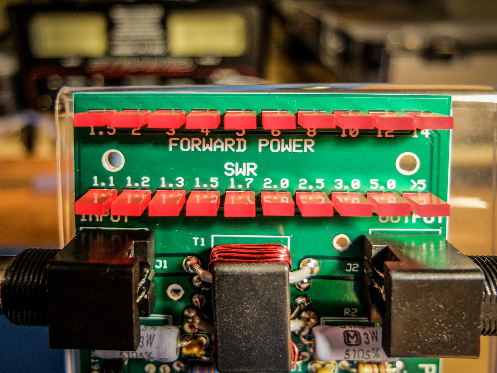 |
| LEDs indicate power in each range and SWR |
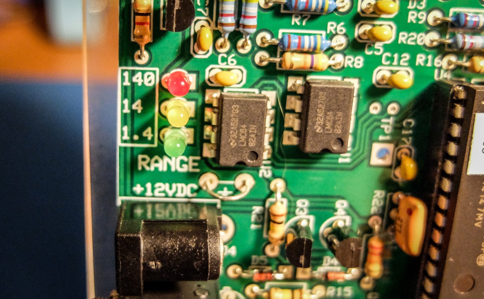 |
| LEDs indicate the power range being displayed |
 |
| Elecraft W1 Power Meter |
That's all for now
So lower your power and raise your expectations
73/72
Richard, N4PBQ
Get a taste of the RF coming and going
Elecraft CP1 - A tasty RF treat
I had some time this afternoon to assemble another Elecraft mini-module kit. This time it was the Elecraft CP1 directional coupler.
 |
| Elecraft CP1 Kit |
Couple what?
Ah, so if your new to this like me you might be asking what does a coupler do? Well it sorta listens in on the signal going out (forward) and reflected (back) and is able to send an attenuated sample of the signal to other devices. It attenuates the sample by either 20db or 30db depending on how you build the kit.The 20db version is good for signals 25 watts and less so that's the way I built it. It was easy to build but my glue under the second toroid wasn't strong enough and you can see it popped up a bit. Also the Elecraft instructions had one confusing instruction concerning mounting the toroids. The instructions say "... When wound and mounted correctly, the enamel wire will emerge from the top of each core and connect to the top hole at each inductor location". Well when you wind a toroid only one of the wires can "emerge from the top of the core" while the other comes from underneath. This confused me for a minute until I finally just went on with the install. Anyway, if you're a stickler for following instructions that one may cause a moment of pause...
The switches for the two outputs forward, reflected (J3, J4) are in the up position when they are not in use. When the switch(es) are in the up position the 50 ohm 3 watt resistor(s) take the place of the switched off output. Don't disconnect an output and leave the switch in the bottom position. I'm not sure what will happen... maybe nothing, probably a bit of a mismatch on the SWR, or maybe it could be like "Crossing the streams" in Ghostbusters. Your mileage may vary.
My uses for a coupler
My old Ten-Tec Century 21 has an analog VFO dial that gives me a good guess at where I'm at but I use an external frequency counter to give me more information. I had it sorta rigged my frequency counter to sample the signal from RF leaked on the shield but I didn't really know how much power I was sending to the counter so this coupler allows it, as well as other devices, to be safely connected to the transmitted signal.I also plan to use the coupler for IMD tests using a oscilloscope and other projects. It's handy device to have in your collection.
My confusion
I will admit I am still such an idiot when it comes to understanding how this stuff works. After I built it I was testing continuity and saw that input/output (J1, J2) both showed a short from ground to center pin on both BNC connectors. I thought I'd mis-soldered something and spent the next two hours unsoldering components and trying to trace the fault...
There was no fault. The way this thing works is a bit of mystery to me but as best I can tell it simply reverses the phase of the signal coming in one side (J1) and leaving the other (J2) and as far as continuity tests go, EVERYTHING has almost zero impedance. I'm still bewildered but it's AC not DC so my continuity tests don't mean much.
But in the end - It works
I finally just resoldered it, scratched my head and thought I'd give it a try. I connected the coupler between my radio and a dummy load and transmitted a watt and noted that the SWR on the radio was fine. Then I hooked up my frequency counter and it worked like a charm sending an attenuated signal to J3 for the frequency counter.
My MFJ watt meter doesn't seem to be all that accurate but I did a power test with it both in-line and absent. My MFJ watt meter measures 300w / 30w so it isn't very accurate at QRP levels. But I noted a slight difference in power reported when the coupler was in-line. If I had to guess by "Mark-One-Eyeball" I'd say the coupler was stealing about 1/2 watt. Maybe a bit more so that's something to consider. I'll know better once I build my Elecraft watt meter since it's accurate down to a tenth of a watt.
That's all for now
So lower your power and raise your expectations
72/73
Richard, N4PBQ
Elecraft BL2
Two Baluns in One
Elecraft mini-module kits offer interesting and useful, little devices and I am learning a bit more about Ham Radio and electronics as I build them. I previously built the Elecraft AF1 audio filter and tonight I assembled the BL2 switchable balun.
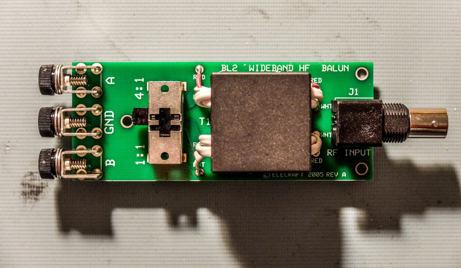
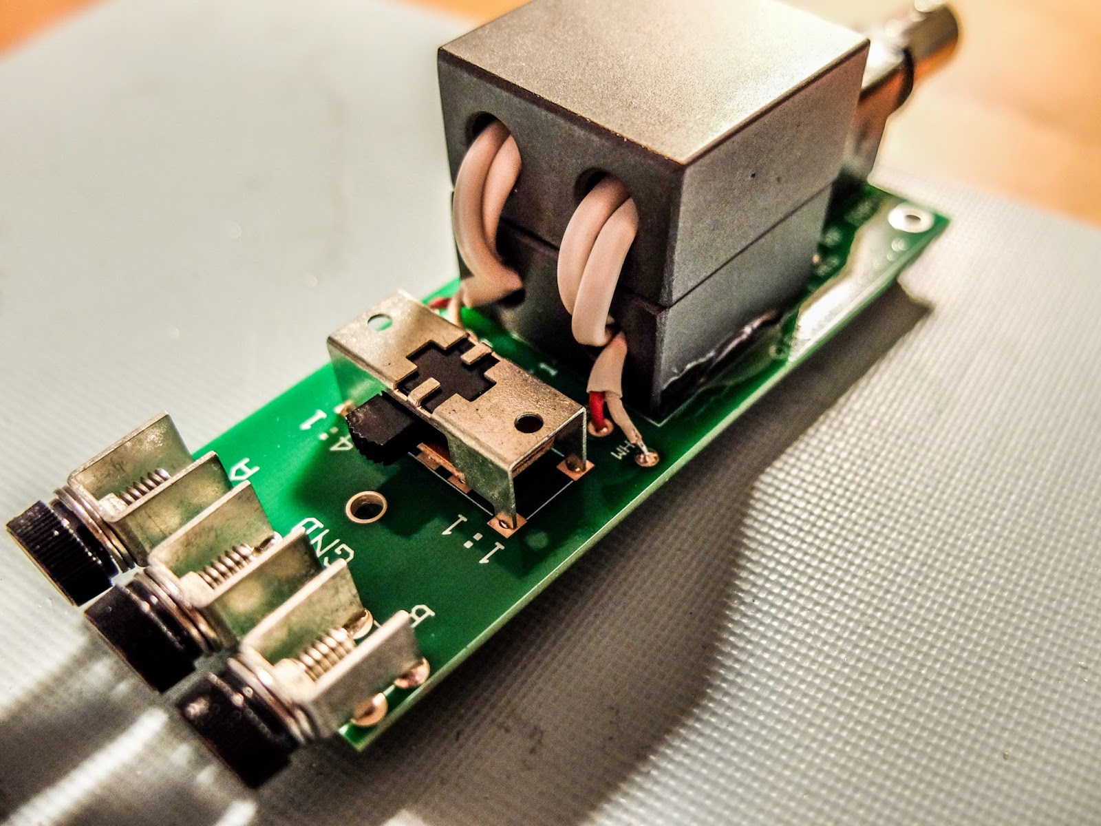 |
| Elecraft BL2 kit |
I wanted a small, low loss, balun for use with ladder line and end-fed antennas that I could switch between 1:1 and 4:1. MFJ makes a commercial pre-assembled switchable balun but I suspect that the quality of its cores do not match Elecraft's.
The kit is obviously an easy build. The most time consuming aspect is getting the four stripped wire ends from the core all equally inserted in their tiny holes.
I tried it out with my attic doublet and the ability to switch between 1:1 and 4:1 made a difference on difficult to tune bands.
According to an email correspondence with Gary (AB7MY) at Elecraft...
According to an email correspondence with Gary (AB7MY) at Elecraft...
- The ground lug is there to be used to bleed off static voltage on an antenna that is not DC or earth grounded.
- We don't recommend using the balun with an end fed wire. It will have too much loss. The balun is for use with a balanced antenna and a low impedance of 200-300 ohms or less.
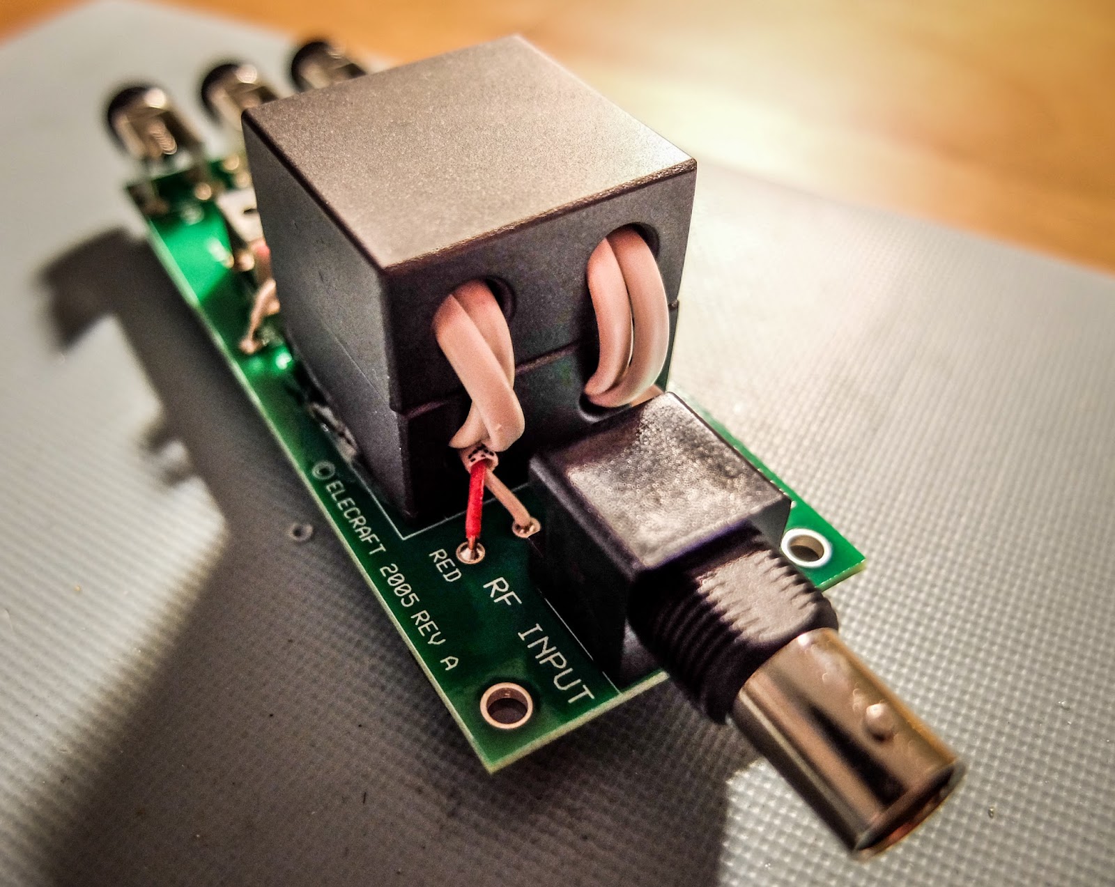
Too Fragile?
The only drawback is the lack of an enclosure resulting in a relatively fragile mechanical connection to the antenna and coax. I had hoped the board would be thicker than average epoxy board with some mechanical reinforcement of the connectors but it's standard thickness and the connections are only held on by their solder points. 450 ohm ladder line is pretty stiff stuff and I saw the connectors flex on the board as I attached the antenna.
I will need to get it in an enclosure before much field use.
Summary
I enjoyed the simple build and winding the cores and tracing out the continuity. I've been studying for my Extra ticket and learning more about inductance. Building even something as simple as a balun is interesting to me.
Update 2-8-2016
N4HAY recently performed a thorough test on the BL2 to measure its loss and current balance capabilities in blog (http://zs6rsh.blogspot.com/) in this blog post.
So lower your power and raise your expectations
72/73
Richard, N4PBQ


