Posts Tagged ‘cheap VHF’
 Recent tinkerings (9 Jan 2011 edition)
Several people have commented over the years that I should “write more” on the blog. I usually respond that I could spend my free time tinkering/hamming or blogging, but not both. Here are a month’s worth of blog posts as freestyle poetry:
- A section on my workshop has been added to k8gu.com under Engineering.
- Discovered that although the SoftRock VHF Ensemble II won’t fit (barely) into the Bud CU-473 diecast box I bought for it, it will fit into an extruded enclosure that housed an ancient X-band radar detector I picked up at Dayton in 2002 in hopes of stripping the Gunn diode assembly and getting on 10 GHz. Bonus points for thriftiness. Photos will follow once I finish the project.
- Did not observe Quadrantid meteor pings with the SoftRock VHF Ensemble II, but did notice something interesting about the W3APL beacon. Need to investigate.
- Have more CE/K8GU QSL cards again, finally. Tonight, I might finish the bureau (and, ashamedly one direct) cards languishing. Some K8GU (and AA8UP, no kidding) bureau cards are sitting here staring at me, too. Not a big project, though.
- Operated the NAQP CW on Saturday (8 January 2011) for four hours and twenty minutes and made 318 QSOs x 128 multipliers for 40,740 points before log-checking discounts. This total is pleasing to me especially considering that it was almost all leap-frogging SO2R search-and-pounce, which can be very fatiguing. It’s fun to see the rate meter stay over 100 when you’re S&Ping. Good Sprint practice.
- Still the best 30 minutes on the radio every week: I operated the NS Ladder on Thursday (6 January) night and made my customary 30 QSOs x 24 multipliers for 720 points. Hopefully, adding 160 will give me some momentum to increase this score back over 1000.
- We had a spell of 50F (10C) weather on New Years’ Eve. So, I put the 2-meter beam back up on the chimney. It was formerly mounted on a steel mast that was ratchet-strapped to the chimney. A strong wind (>50 mph gusts) before Christmas bent the mast (actually a fence top-rail) and I had removed it. I cut the bent lower portion of the mast off and attached the remaining top portion with rotator to a “girder” constructed from two pieces of treated 2″ x 4″ x 10′ lumber joined with a half-dozen lag screws. Again, I ratchet-strapped the entire assembly to the chimney. The present configuration is much stronger and less prone to damage. The 3-element 50-MHz Yagi is still on the ground until I actually get the transverter finished, which should be soon (as it has been for 12 months now).
- Repaired a SoftRock v6.2 downconverter for WF1L and learned that you can solder leads back onto SOIC packages if you’re careful.
- Have had delightful exchanges with KN6X and ZL1CDP about repairing the TS-930S. Some of these discussions (and their fruits) may make it onto the site at some point.
- Back in December, I started integrating the W1GHZ transverters using UT-141 semirigid jumpers with pre-installed SMA connectors obtained on attractive terms from Max-Gain Systems. Mitsubishi RA18H1213G (1296 MHz) and RA30H0608M (50 MHz) modules arrived from RF Parts. May have a lead on something less expensive with more gain for 903 MHz via HA1AG. The big remaining tasks in all three transverter projects are the sequencer and IF interfacing.
- Also in December, I had dinner with NS Ladder father Bill, N6ZFO, in San Francisco at the Hyde Street Seafood House & Raw Bar, which is a favorite of NA Sprint father, Rusty, W6OAT. Yes, I did feel that I was in the presence of greatness. (I had their excellent pork chops since I’m not into seafood, especially raw seafood.) Like most contesters, Bill’s a super, fascinating guy apart from his radio contesting interests.
W1GHZ 1296 MHz RX working!
I spent about two hours last night assembling the W1GHZ 1296RSU and 1152LO boards from his paper “Multiband Microwave Transverters for the Rover—Simple and Cheap.” Once again, I trekked over to W3APL beacon site at lunch and put the pair through their paces on RX with the IC-290H as the IF radio. It worked! Here’s a clip:
One of the interesting things about the 1296-MHz beacon is that it’s FSK, not CW. You’ll notice this after about 15 seconds when it starts sending its callsign. The higher pitch tone is “keyed” and the lower is “unkeyed.” Brian, ND3F, was at the beacon site with us last week to check out a problem (turned out to be a dead power supply fan). He told us that it’s common for microwave beacons to operate in FSK mode so you always have a carrier to tune across (and swing your antenna across). Who knew?!
Anyhow, it’s time to start building the other trappings, including enclosures, sequencers, filters, PAs, and T/R switches! Apart from the PA parts and some connectors, the other components are on-hand and ready.
W1GHZ 903 MHz RX working!

Although I built the W1GHZ 903-MHz transverter and 756-MHz LO boards last winter, I didn’t have time or inclination to test them until this week. These were purchased as a part of the first (October 2009) group buy orchestrated by W8ISS. Instead of the INA-10386 MMIC recommended by W1GHZ, the W8ISS kits featured a Sirenza SGA-3586Z MMIC as the LNA, as suggested by the 4s_microwave group. A better part (with NF < 2 dB), recommended to me by W9SZ, is the the SGA-4586Z, which I used on my 903 board and will use on my 1296 board. This requires the bias resistor (R3, 51 ohms, on the 1296 board) to be changed to 100 ohms.
Since there is a lot of foliage between me and the W3APL beacon, I took the liberty of carting the transverter and IF rig to the beacon site (sorry no photos) on my lunch break yesterday. Sure enough, it worked like a charm with the beacon pounding in on 147.0615 MHz. The nominal beacon frequency is 903.055 MHz, so I don’t know if the difference is in my LO or the not-GPS-locked beacon drifting around. At any rate, I’m pleased enough to continue the project…
The 1296RSU transverter and 1152-MHz LO boards are on the left in the photo above. They have not yet been populated, but that’s an evening’s work.
Keyboard Trays, QRP Rig, and SoftRocks
Time, as they say, has been of the essence of late. So, when I do have time to play radio, I rarely have a chance to write about it. Here are some photos of my latest tinkerings.
Keyboard Trays
Sarah has always talked about using a keyboard tray at work as a part of an ergonomic workstation. Until recently, my work invovled enough variety of computer and non-computer time that I did not think about it. But, after coming home from work with stiff shoulders and wrists, I decided something should be done. While I was at it, I upgraded the HF and VHF/SDR operating positions at K8GU with pull-out trays, as well. These were $10 each at IKEA and pretty easy to install, although I told Sarah that I was grateful that she didn’t witness my contortions to hold them up with my knees while driving the first screws.

Liberating my inner QRPer
Back in high school, I built a Small Wonder Labs SW-40 that I had seen in a QST article. It lived in a variety of enclosures, but spent the last decade in the ugly PC board half-enclosure that looked like a redneck pickup truck at right. I decided to put it into a proper enclosure, being the diecast box at left.

Despite the fact that I made the radio impossible (no room for front panel controls) to assemble the first time I drilled the board mounting holes, I’m pleased with the result. Four dabs of gray epoxy cover the errant holes. I probably could sand and polish those now. The power connector is a pair of Anderson Power Poles.

VHF Softrock and Enclosures
Readers of the blog have seen the screen capture from my new Softrock Ensemble II VHF. Tony does not advertise these on his site because they are not 100% supported with documentation yet. Robby, WB5RVZ has done a great service to the community by preparing step-by-step instructions for most of the SoftRock series. I’m not a step-by-step kind of guy, so I just used his photos showing the locations of the 0.1 uF and 0.01 uF chip capacitors and built the rest my way: mount all chip caps, all SMT ICs, all through-hole ICs and sockets, all through-hole resistors and diodes, all through-hole capacitors, all inductors, and all connectors. It worked right away.
I also have two v6.0 SoftRocks that I built a few years ago while I was in grad school. One of these (for 160) has been a bare board all these years and the other (for 40 and 80) has been living in an ugly little RadioShack black plastic project box. I decided to upgrade them to diecast boxes with external power connectors (also PowerPoles—I’m slowly switching the station over) and a switch for 40 and 80 meters. Here’s the happy family of little radios…

The 160-meter SR v6.0 is on top of the diecast box holding the SR v6.0 40/80. The Ensemble II VHF is on the right. It’s unfortunately too long for either size diecast box. I don’t like the commercially-available box for it. So, we’ll have to see…
144-MHz SoftRock

144-MHz SoftRock Ensemble II VHF by KB9YIG and VE3NEA Rocky 3.6. Yup, that’s W3APL/B (off the back of the beam) and WA1ZMS/B in the same waterfall. How cool is that?! More later… This has many implications for many projects!
VHF/UHF firepower

As if I don’t have enough projects already, I recently obtained these two surplus FAA AM-6155 amplifiers on, as usual, very attractive terms. I don’t have the equipment to properly test them at this point. But, that is coming. The FAA specified these to do 50 watts continuous duty AM. With modification, they will do about 300-400 clean watts with 10 watts of drive on 144, 222, and 432 MHz. Once I get the first two working (on 222 and 432), I plan to find two more of them and use them on 50 and 144 MHz. For 50 MHz, I plan to remove the VHF/UHF cavity and components and install an RF deck using the same Amperex DX393 or Eimac 8930 tube. Comments and ideas welcome. They’re a lot cheaper than bricks! One of my units appears to be at least partially converted already, but I’ve only had it open for a few minutes with my brother Seth, who got all of the mechanical aptitude in the family.
Note: Thanks to WY3X for catching my error on the tube type. He also notes that 300 watts would be a conservative maximum on 432. I plan to run the amps with very low drive after tuning so I can compete in the ARRL’s low power category at 100 watts on 222 and 432.
Super-sizing the “cheap Yagi” (Part 2)
The two most expensive parts of a VHF/UHF Yagi are the boom hardware and the feedpoint. So, I set about eliminating these costs, keeping in mind that I may only have the antenna installed for a year or two at this QTH.
The feedpoint mechanical construction has been addressed in a previous note. However, I should back up and discuss changes from the K1FO Yagi. In its original configuration, the K1FO antenna is fed with a T-match. This is mechanically complex, although some might argue that it’s sturdier than my solution. I elected to feed the antenna with the WA5VJB hairpin design (38-inch element with harpin 1/4-wave stub spaced 1 inch for 19 inches—this is just a convenient and inexpensive ruse for direct feed without splitting the driven element) for the moment. Yes, I am aware that the K1FO antenna has a natural input impedance considerably lower than 50 ohms, but this is just the first (essentially mechanical) prototype. I’ll do some modeling eventually and determine if I can or should optimize it further.
There are four choices for a boom: PVC pipe, fiberglass, aluminum, or wood. PVC is heavy and too flexible for anything longer than two or three feet. (I see people asking questions in forums all the time about building antennas out of PVC. Why bother when wood and aluminum are so readily-available?) Fiberglass is light and strong, but unless you have access to a lot of it, it’s the most expensive of these options and the most difficult to work. That leaves aluminum and wood. Aluminum is hard to beat for strength-to-weight ratio and ease of working. But, wood will give it a run for its money on cost for a reasonable strength up to a point. Since I had a bunch of wood readily available, I elected to build the boom from wood. This is probably pushing the practical upper limit for a wood-boom antenna.
For the boom, I used three pieces of 1 x 2 select pine that was weatherproofed with a clear lacquer:
![]()
The 0″ reference point for the element position measurements is at the left end. Don’t forget to leave a couple of inches at the end.
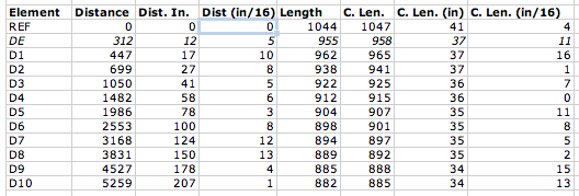
The original WA5VJB designs were optimized for 1/8-inch diameter elements, which is fortunately quite inexpensive (part #8974K14, $2.11/each, working out to a $12.66 antenna, plus about $5 for shipping…you can buy a lot of Al rod and still ship it for $5.) from McMaster. The K1FO designs are provided for 3/16- and 1/4-inch elements, costing $4.13 or $6.03 for six-foot pieces respectively. That was a little rich for my budget, but then I looked at the Metric-dimensioned 6061 aluminum rods. 5 mm is a little more than 3/16 inches and these rods are only $1.64/each ($19.68 for 12 six-foot lengths; examining the element length table below should give you an idea how much savings there is if you get some buddies together to build a few of these…forget buddies, build an EME array)! So, I built the antenna out of 5-mm diameter rods using the 3/16-inch dimensions.
The table contains initial element lengths and offsets in inches. Do not build this antenna! (Do as I say, not as I do.) It appears to be a good performer, but it has not yet been optimized as discussed above. The columns “Dist (in)” and “Dist (in/16)” refer to the integer and fractional portions of the distance, respectively. Likewise, “C. Len. (in)” and “C. Len (in/16)” refer to the element lengths.

Using a cheap Dawia SWR meter at the end of the feed cable, I can tell that the SWR is less than 1.7 across the low portion of the band. Actually, it’s relatively flat around 1.5-1.7 all the way up to 144.5 MHz where I quit measuring. The pattern is apparently good. My “local” beacons that I can pretty much always count on are WA1ZMS (to the southwest) and W3APL (to the northeast). WA1ZMS runs a lot of gas to an excellent antenna system from an even more excellent QTH. I can fade either of them into the nulls when listening to the other. When I turn the antenna, they fade pretty rapidly into the noise, as well. Good F/B, F/S, narrow forward lobe, etc.
So, the upshot is: I built the unmodified K1FO-12 design for 144 MHz on a wood boom for $30 and about 5 hours of tinkering with basic hand tools. I can turn it and my 3-element 50-MHz Yagi with a 60-year-old CDE TR-2 TV rotor. My TS-700S happily blasted 10 watts into it even at SWR of 1.7. I’ll need to verify the cable loss and determine if my newly-acquired Mirage B3016 will tolerate it.
I will post models and photos eventually (once I find the files again…oops) for the 11-element disaster and the 12-element one I built. Yagis are tricky to optimize well. So, I’m somewhat disinclined to mess with the K1FO design and more likely to switch from the WA5VJB driven element to the T-match if I decide that the SWR matters that much.


