Posts Tagged ‘amateurradio.com’
 A Shock-Absorber for a Wire Antenna
Of the three support-points for my wire antenna, one of them has caused me some concern. The end of the longest span of my New Carolina Windom is attached to a rigid, unguyed 12 foot steel mast by a very short length of rope — not nearly long enough to stretch and absorb the shock that a wind-whipped wire might induce in a good storm. Furthermore, this 12 foot mast is set in a small 3′ tripod without any reinforcement below the roof. Obviously this isn’t good enough for a heavy load, but I’m hoping it will suffice to support one end of a 42′ wire. As a precaution, I’ve built a shock-absorber into the system:

This is a spring that I bought at the local hardware store. I didn’t do any calculations to select the thing. I just went through the drawers and handled all the likely-looking springs they had. This one felt about right when I pulled on it. I tied it into the 3/32″ braided dacron/nylon rope with a loop long enough to match the length of the spring when fully extended. The electrical tape is to prevent chafing for as long as it stays on.
The spring is strong enough that on a calm day it doesn’t stretch at all, but it still has plenty of give if the wire gets to whipping around. Will it help this antenna-system weather the storms we get out here in western Minnesota? Time will tell!


![]()
Waterproofing Coaxial Connectors
For a great tutorial on waterproofing coaxial connectors, check out this post by Paul, AE5JU, over at K9ZW’s blog. I didn’t use Scotch 130C Coax Seal like he does since by the time I discovered its existence I was out of time to acquire it for this project. Next time!
[Update: After the helpful comments I received on this from VE3WDM and others at amateurradio.com, I’ve ordered some coax seal and plan to finish the job as soon as it arrives. What I’ve done here is better than nothing — certainly good enough until I can get the good stuff — but it doesn’t afford long-term protection.]
[Update: When I went to put on the coax seal, I discovered my nice pretty electrical tape already coming apart after less than two weeks! Use coax seal! Another thing I’ve learned about is “Magic Tape,” the self-amalgamating silicone tape you can easily find even at stores like Target and Walgreens. Some hams have told me it works great to put over the coax seal.]
What I did do was wrap the connectors with teflon plumber’s tape, then covered it with black 3M electrical tape. The teflon tape is intended simply to keep adhesive from gumming up the connector. I put several layers of electrical tape down and made sure to wrap the last layer up, i.e. toward the sky, so that the turns are stacked like shingles on a house with their seams pointed downward. Here’s a slideshow:


RF Choke
The New Carolina Windom uses part of the feedline as a vertical radiator — the voltage balun used to feed the off-center fed dipole allows common mode current to travel down the feedline. How do you determine how much of the feedline radiates? From what I’ve read, you do this by placing an RF choke (sometimes called a “line isolator”) at some point in the feedline to clamp off the common mode current. For an 80 meter version, you put the RF choke 20 feet below the feedpoint. For a 40 meter version (like I’m building), you put it 10 feet below the feedpoint.
To build my RF choke I followed the instructions provided by Len Carlson, K4IWL. In an addendum published here, Mr. Carlson wrote:
A note about the choke [between the balun and the feedline]: The choke [line-isolator] is simply a straight piece of coax with ferrite cores strung on it. Just use the same coax that you are using for the field line from the Xceiver to the choke. I have made a mod to the choke also. Instead of bending it back inside of the CPVC tube, make it a straight piece of coax about 0.3 meter. The length is not critical but should be no shorter than about 12 inches. Use as many ferrite tubes that will fit in-line on that length.
I built my RF choke using 12 FB-56 ferrite beads (mix 43) from Palomar Engineers strung on a piece of RG-58 coax and secured on each end with wire-ties. While Mr. Carlson chose CPVC for a lighter enclosure, I used PVC. In order for the SO-239 bulkhead-mount coax connectors to fit in the endcaps, I had to go with 1 1/4″ pipe. This did make for a pretty large enclosure — the beaded coax in the pipe does slop around a bit in there when shaken. If I have to do this all over again I’ll figure out some way to secure the innards of this thing (maybe by injecting some expanding foam?). As it was I inserted a few inches of double-sticky foam mounting tape inside the last end to be sealed, which did help somewhat.
I attached one end of the beaded coax directly to an SO-239 connector/end cap, but the other end required several inches of slack to stuff into the tube when it came time to push the final end-cap onto the pipe.
Here is a slideshow of my RF choke. After I took these photos I covered the coax connectors with cling-wrap and spray-painted the whole thing forest green.


1 KW 4:1 Ruthroff (Voltage) Balun
Building baluns is just about the easiest construction project there is in ham radio. It pays to build your own, too. I’ve read reports from some disappointed hams out there who have paid good money for poor-quality baluns. The ones worth buying might cost you almost twice what you’ll pay to build your own. So I decided to build my own balun for the New Carolina Windom that I’m putting up. The total cost of materials was $40.  Balun")
The New Carolina Windom is essentially an off-center-fed (OCF) dipole. The big difference is in the balun that you use to feed the antenna. A current balun is the proper choice for an OCF dipole, since it effectively chokes common-mode current from standing on the feedline. But for a New Carolina Windom you want common-mode current on the feedline, since you deliberately use a portion of the feedline as a radiator (an additional RF choke is necessary to clamp off this common-mode current at a certain point on the feedline, but I’ll discuss that in a future post). Therefore, you use a voltage balun, not a current balun. The voltage balun allows some common-mode current to stand on the feedline.
Now, before I go any further I must warn you that I am not an electrical engineer. Baluns are a bit mysterious to me, but from the discussions I’ve read on the internet it seems I’m in good company. If you want to learn more about baluns, I recommend Jerry Sevick’s book, Understanding, Building, and Using Baluns and Ununs, available here.  This book has everything — easy-to-follow instructions for building different kinds of baluns, helpful tips from Sevick’s own experience, as well as some deep discussion of theory that should satisfy even a graduate student of electrical engineering. I followed his instructions for building a 4:1 Ruthroff (voltage) balun.
When building a balun there are several factors you must take into consideration. Do you want it to handle a full kilowatt, or are you willing to be forever limited to QRP? Now, I enjoy QRP (I love my little HW-8!), but I also want to have the option for QRO. Therefore, I chose to use not just one toroid, but two — and to use teflon-coated wire instead of the cheaper stuff you can get away with for QRP. I bought 100 feet of stranded (that’s right, stranded — it works fine!) 14 AWG silver-plated copper teflon-coated wire off of ebay for $34, shipped. That’s enough to build quite a few baluns!
When choosing the wire you’ll use in your balun, you must choose the wire size carefully. The diameter of the conductor and the distance between the center of each conductor determines the impedance of the pair you’re winding around the core. In a 4:1 balun, you want an impedance of 100 ohms. Since impedance around a core is only about 80% of that in free space, that means you want a guage and spacing that gives you 125 ohms. You can use the handy caculator for “Impedance of 2-Wire Transmission Line” at KW2P’s website, or you can figure it out yourself using this formula:
Zo = 276 * log 2(S/D)
S = distance between the centers of the two wires
D = diameter of the wire
Any unit of measurement works (inches, mm) as long as you use the same unit for both S and D.
You’ll notice that the spacing between the wires is critical. I used thin strips of strapping tape to tightly bind the wires together every couple of inches, and watched closely to make sure no gaps appeared as I wound the pair on the toroid.
Another thing you have to decide on is the permeability of the core. There’s lots of debate about this. I followed Sevick’s recommendation to use a permeability of 125 (ferrite mix 61). I purchased my two FT-240-61 cores from kitsandparts.com, stacked them, and taped them together using 3M Scotch glass-fiber strapping tape.
Now, what to put the thing in once you have it wound? The last time I built a balun, I put it in a project-box from Radio Shack. I won’t do that again — the plastic is just too thin. You want something strong enough to stand up to the stress put on the box by the eyebolts that you use to hang the balun and connect the antenna-wire to it. PVC pipe and end-caps are popular, but to house a balun this big it ends up being fairly expensive and downright heavy! I found the perfect solution at Menards for just under $7. It is a weatherproof enclosure made from PVC plastic and comes with a neoprene gasket to seal the cover to the box. I used neoprene washers for all the bolts and sealed all the entry-points (except for the binding posts and the bulkhead SO-239 coax connector) with silicone.
I spent a little time in the hardware store picking out the nuts and bolts for this thing. You want to make sure the bolts don’t work loose, so use lock-washers and lock-nuts where you can. I also used star-washers for each lug that I fastened to a bolt. Star washers have teeth in them that cut into the metal, ensuring a good connection. A fellow at the hardware store also cut me a small square of heavy plexiglass for 50 cents to use for securing the wound toroid inside the box.
When you have built your balun, you can test it by putting a pure-resistive load across the terminals and measuring the SWR across the spectrum you intend to use. For a 4:1 balun, that means a 200 ohm load (4*50=200). The SWR should be 1:1 across the spectrum. Here’s a video showing the test of the balun I built:
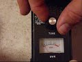
It looks good! I’m looking forward to using this balun. If you would like to build one of these and have any questions, ask away. I’ll give you whatever advice I can. Just remember — you’ll get what you pay for!


![]()
Antenna-Day #2, in My Son’s Words
I’m afraid we still don’t have the antenna up, but things are looking good to get it done next week. I have lots of stuff to post regarding this project, but that will have to wait until I have more time. In the meantime, here is my son’s account of what we did on Tuesday of this week:
Helping Dad Build His Antenna, Day 2
by Antonio Mitchell, Thursday, October 13, 2011On Tuesday we began our official work. Dad bought his parts that were on his shopping list and also a titanium drill bit. We kept getting a step closer to finishing our project with each thing we did. It felt good to be getting the project done.
When Dad came home from his shopping trip we began to get ready to go onto the roof. The bolts for [one of] the tripod’s feet were put on, and also the ladder was brought out. We had a bucket which Dad tied some knots to. The bucket was to put things in that would help us put up the tripods. In the bucket were bolts, drill, level, roofing compound, and tape measures. My dad hauled up the first tripod using a rope. Then after that came the bucket.
Once everything was on the roof we set the tripods on each end of the house. We started with the smaller tripod. I made sure it was level and Dad drilled the holes.Once the holes were drilled we spread roofing compound. I helped put the tripod back, while Dad screwed the bolts in. We did the same for the other tripod as well.
After the tripods were on the roof we finished working on the mast. The titanium bit really worked well. It took us till supper-time to finish the tripod and the mast. My dad’s back wasn’t doing well so we did not get to put the mast on the roof. Hopefully soon.


![]()
Antenna-Day #1, in My Son’s Words
As my son’s homeschool teacher I’m giving him plenty of writing assignments this year. Yesterday I asked him to write an essay, and I told him he could write it on anything he wanted. Here’s what he wrote:
Helping Dad Build His Antenna
by Antonio Mitchell, Tuesday, October 11, 2011My dad has been meaning to build his antenna for his radio for a while. We (my dad and I) finally got motivated and had some free time as well to build the antenna. We began yesterday to build it. Some complications slowed us down.
Yesterday, we went to Wilmar. The first stop was Walmart. When we were in Walmart I got my glasses back. After that we began our search for parts at Menards. It took us a while to find some parts. The whole trip to Wilmar, shopping, and going home took quite a few hours. My dad had to meet with a church member. While he was gone he got a piece of metal cut for the tripod legs.
When he came home several hours later my mom and I were raking leaves. He began to put together a jig to help hold the poles together. We began to drill holes into the poles. It took both of us to do it. The bit finally broke. After supper my dad worked on making a balun. He also made a new shopping list of parts. It will be a great joy to see the antenna up on our roof.


![]()
Enough Planning! It’s Time to Put This Antenna Up!
Hopefully Monday will be an antenna-building day. I don’t know that it will all come together in one shot, but if I don’t get this project going it’s never going to get done.
I spent some time in the hardware store yesterday, picking out the many different bits and pieces that I’ll need for the job. Hard to believe how much it all added up to. Gulp! At least I had a coupon for $10 off of my purchase. As it is there are still a couple more little things I need, but I’ll have to drive up to Willmar for those on Monday.
Here’s a rough sketch that I made last March, dusted off and updated slightly. There are still a couple of unknowns — those are the figures in red. I’m not certain that I’ll need to attach anything to the adjacent church-building, since I may get away with just draping the wire in a nearby tree. But I’ll figure that out as I go. I’ve planned enough! It’s time to put this antenna up!


![]()


