Posts Tagged ‘amateur radio’
 PARP 52–QSL Bureau and more
 The Practical Amateur Radio Podcast episode 52 is now available for download or stream. You can subscribe via iTunes, Zune or stream directly from MyAmateurRadio.com Want to stream on the go from your favorite smart phone device? You can do that as well via our mobile site.
In this new episode, I discuss the QSL Bureau Service as it relates to US Amateur’s. The bureau service is a great, inexpensive method of QSL’ing those DX contacts. Our featured website segment discusses the Ham Nation podcast/netcast as well as Mike Baxter, WA0XTT.
Please visit MyAmateurRadio.com to listen or download this new episode.
Thank you for listening and thank you for sharing your knowledge with others. The Practical Amateur Radio Podcast, creating Elmers one podcast at a time.
Until next time…
73 de KD0BIK
DIY Magnetic Loop Antenna – Part 2
Part 1 of the DIY Magnetic Loop Antenna covered mostly theory and materials so now its time to move on to designing the magnetic loop antenna (MLA).
If you have priced a commercially made MLA you’ll see prices start at $400 and keep going up, and up. If they cost so much you would think they must be difficult to build or use expensive parts, right? Well, it is certainly possible to spend more and get a higher quality MLA but a low cost MLA will still work very well.
For the purposes of this article we’ll assume that you want to build a loop to cover the 20-10M bands. I’ll run through the calculations required to build the MLA.
The required information for the MLA calculator is:
- Length of the loop
- The conductor diameter
- Frequency/s of operation
- Input power to the antenna
- We don’t really know the best length of the loop at the moment so I’ll pick 9 feet circumference as a starting point (It’ll still fit in the trunk of my car)
- Since we seem to be having better luck with sunspots now I’d like to try 10M so we’ll start with 29 Mhz as the highest frequency we’ll use.
- I have some copper pipe left over from an ice-maker install, it is 1/4 (0.25) inch in diameter.
- Input power to the loop will be 100W.
 A peak voltage of 5181V will require a minimum spacing of 1.7 mm (peak voltage / breakdown voltage per mm) between the closest conductors in the capacitor. That would rule out an old air spaced variable capacitor from a vacuum tube radio but you could still use a wide spaced variable capacitor from an antenna matching unit or transmitter. A vacuum variable capacitor would be great (watch the minimum capacitance) or a home-made capacitor would also be fine provided you checked the breakdown voltage of the insulating material.
 My Morse Journey
As I’ve mentioned many, many times. My attempts at learning Morse code or CW as a teenager were unsuccessful. While I’ve mentioned my excuse was too many distractions (cars, sports, girls). I also believe my failure was a learning block which I couldn’t overcome. Perhaps another way to word this was a learning block I didn’t know how to overcome.
Since getting my license in 2007, CW has been a mode I’ve wanted to operate. I will admit that I’ve fiddled around in Ham Radio Deluxe DM780 and have also downloaded and installed other software applications to decode via the computers soundcard to text translation. I’ve decoded many times, but have never actually attempted to send via these mechanisms.
Please understand that what I’m going to say next is my opinion and only my opinion. But if I have to use computer software to send and receive CW signals, I might as well stay away from that mode. Again…this is my opinion for my own operational style and my own way of thinking.
So having said that, I am in the process of researching methods of learning Morse code. I’ve spent some time talking to some friends and researching information on the internet. I plan to wrap up this discovery phase and get started in the next few days.
While I know many learned CW from simply studying the dots and dashes which make up each letter or from listening to code tapes. I’m looking for alternative methods as I’ve tried the code tapes and studying an A is .- with not much success. Of course, I also understand I’m a much different person now than I was 30 years or so ago. Most of this will be similar to overcoming my obstacles with earning extra last summer. Meaning, I just need to focus and get it done but at the same time not setting unnecessary pressures on myself.
Morse code is very much alive on the bands and it is a mode I dearly want to enjoy. I’ll be certain to most frequent updates to share both my successes and frustrations along my Morse journey.
Until next time…
73 de KD0BIK
Handiham World for 15 February 2012

For Handiham World, I’m…
Patrick Tice, [email protected]
Handiham Manager
Will Solar Cycle 24 Be 17 Years long?
Read an interesting Blog today about three Norwegian scientists who used historical solar green corona emissions data to predict that Solar Cycle 24 will be 17 years long, 4.5 years longer than Solar Cycle 23:
http://wattsupwiththat.com/2012/02/11/quantifying-the-solar-cycle-24-temperature-decline/
The Norwegian study referred to in the Blog is available for download here:
http://arxiv.org/pdf/1202.1954v1.pdf
We are currently in Cycle 24 which has, thus far, been lackluster as far as sunspots and solar flux go. I haven’t read the Norwegian study in detail, yet – I’m curious to know when the Norwegian authors think Cycle 24 will peak and at what level of solar activity and how they reached their conclusions.
My fingers are crossed for a vigorous Cycle 24 peak as it would be nice to have a bout or two (or three) of temperate latittude F2 propagation on 50-MHz before sliding down to the Cycle 24/25 trough!
73
Bill AA7XT
HamLog App Upgrades–WOW!!!
I’ve blogged about iOS apps before, but I can’t remember if I’ve previously mentioned anything about HamLog. I’ve owned HamLog for a few years now. I’ll honestly say for the record I don’t currently use it, but feel that will soon change.
HamLog is an iOS and Android application developed by Nick Garner, N3WG. Nick has developed over a dozen different apps. One I mentioned briefly in another blog post is his Pocket SOTA app. You can view Nick’s listing of Apps from his website.
As I mentioned, I’ve owned HamLog for a few years. I believe Nick developed and released it in 2009. I’ve watched Nick make many changes to the HamLog app over the years. While I’ve tried using it to log contacts, I found I could log via pen and paper much faster. Especially with operating SOTA, you can easily find yourself generating a large pileup. The extra time it takes to manually key in all the info was just something I wasn’t interested in for my own operational setup. Until now…
Please take a few minutes to watch this video. Nick introduces some new enhancements to the HamLog App as well as a new piece of hardware called Pigtail Air. Pigtail air will allow for true rig control through the HamLog app and of course will speed up the logging process.
I believe the Pigtail Air device, coupled with my new KX3 (when it arrives) and my iPad will make a fantastic SOTA or portable logging setup. I’ll now have an excuse to buy that Otterbox Defender iPad case.
Until next time…
73 de KD0BIK
Heathkit’s first amateur transmitter – Heathkit AT-1
The Heathkit AT-1 represents the commercial embodiment of the simple Master Oscillator Power Amplifier (MOPA) transmitter using a crystal controlled 6AG7 oscillator plus a 6L6 final output tube.
Although it was possible to design and build a simpler transmitter, the goals of output power and stability could become mutually exclusive when trying to operate with only one tube. For a novice class license holder of 1951 the Heathkit AT-1 represented a solid performing rig that would be relatively easy to construct and operate.
The Novice remained the primary entry license until the Morse code requirement was eliminated for Technician licenses in 1990. On HF it permitted code transmissions only, with a maximum power of 75 watts, (input to the transmitter’s final amplifier stage) on limited segments of the 80, 40 and 15 meter bands.
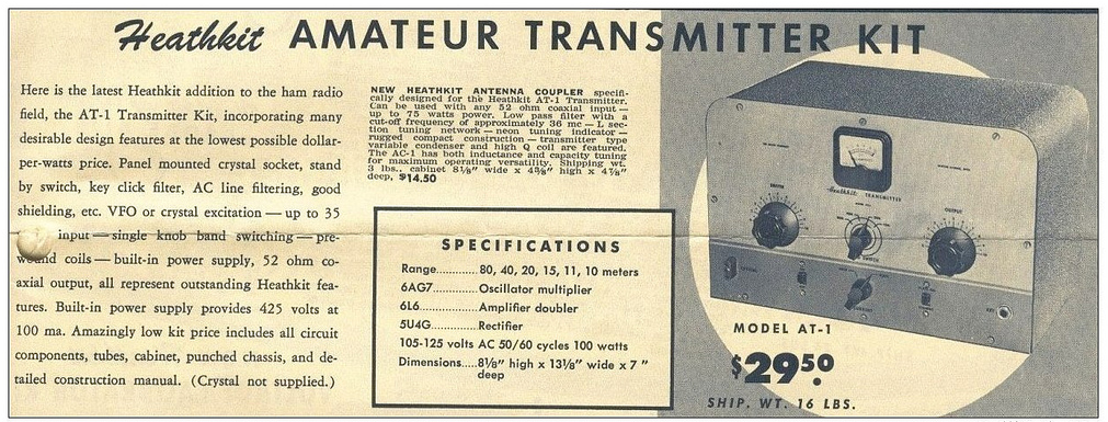 |
| For $29.50 and the loan of a few tools you could get some use out of that new novice license |
The earlier MOPA circuit from the ARRL handbook of 1941 below shows a layout remarkably similar to the circuit of the AT-1 although it is designed for plug in coils rather than the band-switching arrangement of the later Heathkit transmitter.
| MOPA transmitter using a 6L6 and an 807 as the power amplifier (ARRL Handbook 1941) |
For a little added complexity MOPA transmitters generally offered better stability of frequency and keying waveform than single tube crystal controlled or self exited rigs. The straight forward design of the AT-1 should have looked familiar to novice class hams after studying the ARRL handbook or other radio publications.
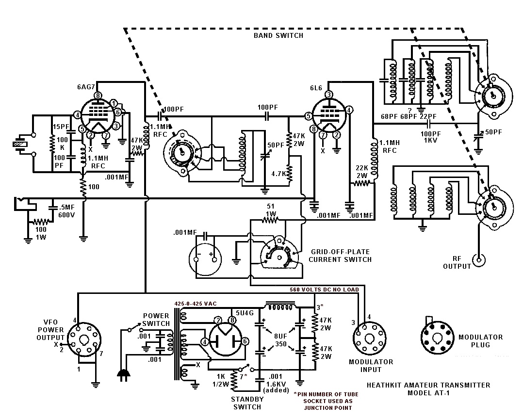 |
| Heathkit AT-1 Circuit diagram showing band-switching arrangement and link coupled output |
Once the novice had upgraded his license the AT-1 could be expanded by the addition of the Heathkit VF-1 variable frequency oscillator to allow transmission on any frequency within the allowed band.
 |
| The Heathkit VF-1 Variable Frequency Oscillator |
The VF-1 covered 160-80-40-20-15-11-10 meters and used an OA2 voltage regulator tube to provide a stable voltage for the oscillator. Ceramic coil forms, solid construction and high quality components were used to help increase stability.
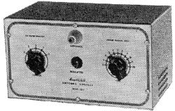 |
| The Heathkit AC-1 Antenna Coupler. Designed to attach to a single wire by the insulated post on the front panel. |
 |
| Heathkit AC-1 Antenna Coupler circuit diagram |
Although Heathkit did not produce a AM modulator for the AC-1 there is provision for modulator connection on the rear panel. The earlier ARRL manuals have several suitable circuits for modulators that would work with the AC-1. Most functioned by driving a modulation transformer with the output from an audio power amplifier. The secondary of the modulation transformer would be carrying the DC plate supply for the power amplifier tube plus or minus the instantaneous voltage of the audio waveform. By changing the plate voltage to the final amplifier tube the radio frequency output would be controlled by the amplified audio frequency resulting in amplitude modulation.


