Posts Tagged ‘amateur radio’
 Ham Radio Deluxe
![]()
You may remember back in September, I blogged about the news of the developer (Simon) of Ham Radio Deluxe selling to several US hams. I followed one of the threads over on the QRZ forums until I basically grew bored of the hate and non-sense being discussed. At that time (Sept. timeframe) no one really knew what was going to happen or when we would learn the fate and future of the HRD software. While many had conjured up ideas of users receiving cease and desist letters, as I stated then (and what has been proven since) I didn’t think anyone had anything to worry about.
As the old year (2011) turned into the new year (2012) news began to surface about the plans for Ham Radio Deluxe. The new owners (Rick Ruhl, W4PC Mike Carper, WA9PIE and Randy Gawtry K0CBH have since released two free updates (version 5.1 and 5.11) and offered users a $59.95 support plan which covers version 5.11 and version 6 at no cost. Ham Radio Deluxe version 6 is scheduled to be available around the Dayton Hamvention timeframe of this year.
I learned about HRD before I even earned my license and was using it with my Yaesu FT-897 as I tuned around the bands listening. Once I got my ticket I used it to log my first HF QSO’s on 10 meters and have used it since. The value of what Ham Radio Deluxe brings to me in the enjoyment of the hobby is certainly more than I can associate a cost to. I’ve looked into alternatives for casual QSO logging, rig control and the digital modes and have found nothing that even comes close to beating HRD in its present form.
After watching the video below, I’m actually excited about the opportunity for HRD version 6 and beyond. Some of the new features discussed will be an integration between N1MM logger and DM780. This to me will be worth the investment to upgrade to version 6. I do love N1MM logger for contest operations, but I rarely use anything other than DM780 for digital modes. When I try to use other applications for PSK or RTTY, I’m like a fish out of water. For that reason I don’t do a lot of true digital contest operations.
If you haven’t already, please take about 52 minutes of your time and watch the video below which is made available by Gary Pearce, KN4AQ and his Amateur Radio Video News (ARVN) service.
I’ve had no contact with any of the three mentioned owners and simply blog about this particular subject because I want to. The opinions expressed are simply my own. I fully understand and appreciate that not everyone will share my thoughts and opinions on this subject.
Until next time…
73 de KDØBIK
Handiham World for 07 March 2012
Welcome to Handiham World.

On March 5, 2012 the latest version of the United States Amateur Radio Bands chart from ARRL became effective. If you will recall, last November the FCC made some changes to the 60 meter band, and this new chart brings us up to date. Of course that will mean that you will want the latest version on your computer or in your ham shack for reference. Prior to this week, only upper sideband operation was allowed on the channelized 60 meter band. Few of us had actually made the move to 60 meters and made contacts, partly because of the odd restrictions in frequencies and modes, but also because many antenna systems just didn’t tune on 60 meters. Even so, those who were adventuresome took the plunge and were delighted to find that propagation on 60 meters made it quite a useful alternative to 75 and 40 meters since it has characteristics of both of those popular bands. This morning I was surprised to be listening on 5.330.5 MHz and hear a station in the southeastern United States calling CQ using CW at around 30 words per minute. He called off and on for perhaps 15 minutes, obviously using a programmed keyer before he was finally answered by a station somewhere on the East Coast. I have to admit that 30 words per minute is too fast for me to copy comfortably, so I had to listen up to make sure I was hearing correctly. After all, only upper sideband operation was allowed on the 60 m band. When I was sure I was copying the call sign correctly, I decided to check the frequency chart on my wall just to confirm that only upper sideband operation was allowed. The chart confirmed this, but then I recalled the changes that the FCC had made and decided to check the ARRL website for a new frequency chart. Sure enough, a new version was available and had been released just two days ago!
The difference is pretty significant, because the effective radiated power, the modes of operation, and even one of the channelized frequencies have been changed. Let’s go over the “new” 60 meter band as shown in the ARRL Frequency Chart. Here is the new information for our blind members in an easy to listen format:
The 60 meter band is also known as the 5.3 MHz band. Only General, Advanced, and Extra Class licensees may use 60 meters. All of these license classes have full band privileges.
The five channels available on a secondary basis with a maximum effective radiated power of 100 W PEP relative to a half wave dipole are:
5.330.5 MHz
5.346.5 MHz
5.357.0 MHz
5.371.5 MHz
5.403.5 MHz
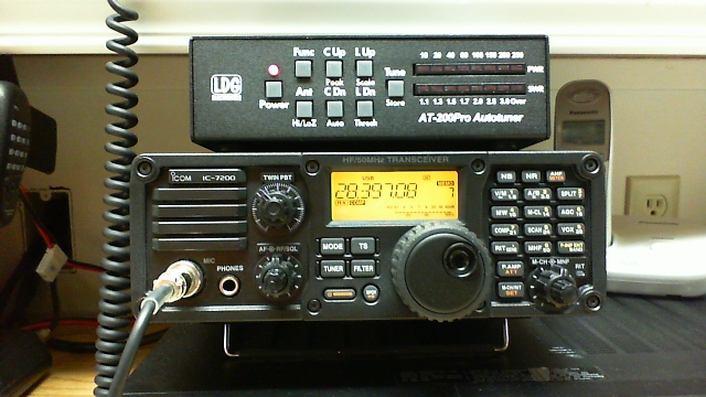
Some readers and listeners may find it odd that we have listed two decimal points in each frequency. I decided to do it that way because this preserves the concept of the “5.3 MHz band”. The ARRL chart lists kilohertz, so that the frequency would read 5330.5 kHz, for example. On my ICOM IC-7200 transceiver the readout follows our listing in megahertz and has two decimal points.
Only USB suppressed carrier voice, CW, RTTY, and data such as Packtor 3 transmissions are allowed on the 60 m band.
There is a bandwidth restriction on 60 m. Bandwidth is limited to 2.8 kHz centered on 5.332, 5.348, 5.358.5, 5373, and 5.405 MHz respectively. (For example, you will be on the right frequency if you use upper sideband and tune to 5.330.5 MHz, which is the carrier frequency.)
All things considered, the 60 m band has been improved by these changes. It is still quite unique in its channelized nature, but the addition of new modes of operation do increase its versatility and will make it more attractive to a wider variety of users. Although there is no restriction on which mode of operation may or should be used on which channel, I did hear the CW station on 5.330.5 MHz, perhaps because that is the traditional lowest frequency spot on the band where CW operators might decide to congregate. Perhaps at some time in the future there will be at least an informal band plan beyond the more or less agreed upon use of 5.403.5 MHz as a DX frequency. The increase in power from 50 W to 100 W makes the band more useful still, especially during summertime band conditions when more power is likely to be needed to be heard above thunderstorm static.
I hope you will consider giving the 60 m band a test drive if you have a General Class license or above and an antenna that can be tuned to 5.3 MHz. I think you will be surprised and delighted with the propagation characteristics on 60, and will likely add it to your regular list of useful frequency bands.
For Handiham World, I’m…
Patrick Tice, [email protected]
Handiham Manager
DIY Magnetic Loop Antenna – Part 3
Well, I finally have had time to sit down and put together part three of the DIY Magnetic Loop Antenna, sorry it has taken so long!
This post will cover building and coupling the loop to your transceiver. After reading through posts one and two you should have a good idea of the parts you’ll use and the physical dimensions of the main loop.
DIY Magnetic Loop Antenna – Part 1
DIY Magnetic Loop Antenna – Part 2
Most magnetic loops have the capacitor at the top of the main loop and the gamma match or matching loop at the bottom, this arrangement avoids running the feed-line through the center of the antenna.
You can assemble the main loop from continuous copper tube or from eight straight sections and 45 degree joiners. Make sure you have a blow torch or propane torch to solder the joints as you’ll need more heat than a soldering iron can supply. Whichever way you decide to build the main loop make sure that all joints are soldered or clamped as securely as possible, you want the lowest resistance possible to avoid your output power turning into heat. Other materials can be used for the main loop such as aluminium or low loss coax but copper pipe is easy to work, has low resistivity and available from just about every hardware store.
To construct the frame of the antenna you can use PVC pipe. It is a cheap and relatively sturdy building material and is available in a range of thicknesses, just about any hardware store will stock a wide selection of fittings. It insulates well and can be glued once you are sure your project is in its final form.
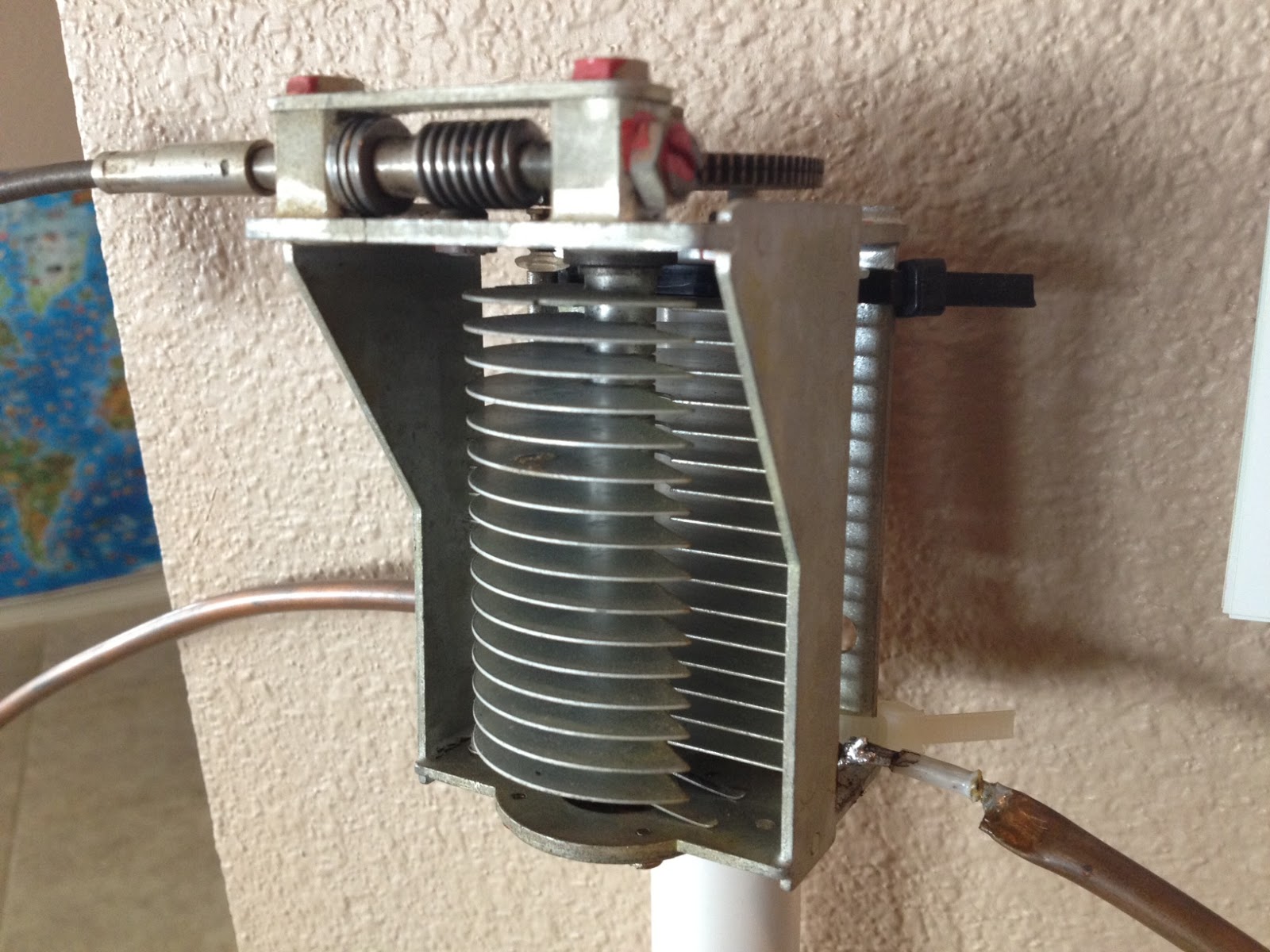
Once the main loop is constructed you’ll need to connect your capacitor to the two ends of the pipe at the top of the loop. Depending on the capacitor you may want to solder tags to the ends of the loop so they will be easier to attach. Copper pipe is a great conductor of heat and takes a lot to heat up and solder while it is not advisable to apply the same amount of heat to your capacitor.
It is also a good idea to attach the capacitor to a solid support so that the connections are not under strain.
The main loop and the capacitor forms the resonant circuit of the magnetic loop antenna.

To couple the main loop to your transceiver and match the expected 50 Ohms impedance you can use one of two methods. Probably the easiest is to use is a loop of insulated wire 1/5 the circumference of the main loop. The smaller loop is placed at the bottom of the main loop and can be shifted around to provide the best match. If you have an antenna analyzer you’ll be able to set it to the desired frequency, tune the variable capacitor for resonance and then move the small matching loop around till you have achieved close to 1:1 SWR. If you don’t have an antenna analyzer you can tune the capacitor for the greatest received noise and then on low power tweak the capacitor and move the coupling loop around for best SWR. Do NOT touch the loop while it is transmitting, use a wood or plastic rod to make adjustments as there are high voltages and intense RF fields near the loop.
An alternative to the coupling loop is the gamma match. The shield of the coax feed cable is connected to the base of the main loop while the inner conductor is connected to a point approximately 1/5 of the circumference around the loop. Its a good idea to use stiff wire (large gauge) for the gamma match as it can be critical of the position and orientation and once you have it in the right position you won’t want to move it again.
It would be preferable to have the ability to remotely tune the loop. A motor with a reduction gear could be used to move the variable capacitor but because the point of resonance is very narrow there should be a way of slowing the motor down. A simple control circuit using variable pulse width modulation could be used to slow the motor down while still retaining enough torque to move the capacitor. Whatever method is used to move the capacitor it should be well insulated from the other components of the antenna. Several thousand volts are generated on the MLA and care should be taken to ensure they don’t find their way onto control leads and back into the shack. Control leads should also be wrapped around toriod inductors as they leave the near field of the antenna to reduce the possibility of RF travelling along them.
With a SWR bridge and microcontroller you could build a fully automatic tuner that swept through the range of the tuning capacitor when the SWR rose above a defined limit indicating that the transmit frequency had changed.
With a little creativity and knowledge you could have an impressive MLA the equal of multi-thousand dollar military style units.
Hopefully this has given you some ideas for constructing your own loop antenna. Regardless of if you go top-of-the-line and buy a vacuum variable or build for economy and QRP you’ll have a compact, useful and unique antenna.
Handiham World repost for 01 March 2012
Welcome to Handiham World.
Ice! Are you ready?

Photo: Ice and snow cling to the dipole at the WA0TDA station in Minnesota. The 450 Ohm feedline and the antenna wire are carrying a coating of heavy ice, as are the nearby tree branches.

Photo: Iced birch tree branches pull the antenna wire down.
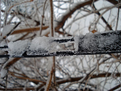
Photo: Heavy ice coats the 450 Ohm ladder line in this close-up.
Here it comes: The annual Spring severe weather season is here in North America. Tornadic winds hit in the southern Midwest states of Missouri and Kansas last night, while the same huge weather system brought Minnesota freezing rain and snow. The transition from winter to summer often means that we will be visited by bad weather that can take down antennas and put stations off the air at the very time their communications capability may be needed. This storm was well-forecast because it was being watched even as it approached the west coast from the Pacific. Computer modeling lends a new degree of confidence in such forecasts, so it is perhaps a bit easier than ever to be ready.
The problem for any given amateur radio operator is that forecasts cannot predict exact weather circumstances in a small geographic area. In this particular storm, heavy snow fell north and west of my location but we only got about 3 inches worth. Our snow was preceded by rain – freezing rain – which coalesced around antenna wires and tree branches. When the snow came, it added to the mass already collecting on the branches and wires. This was a prescription for power outages because tree branches would inevitably begin to break under the weight of the ice and fall across power lines. The power lines themselves, if in the clear, seldom collect enough ice to fall on their own. Sure enough, this morning almost 15,000 customers were without power here in the Twin Cities. Since the storm was more severe in the northwest part of the urban area, that was the place with the most power outages. Even so, in my town there were over 400 customers without power. Our power never failed or even flickered, probably partly because of just plain luck and good switching at the power company to keep failed power lines from bringing down the entire system. One thing I looked for specifically when purchasing my property was underground power lines. I have lived in too many neighborhoods where tree branches fell across lines and cut the power in almost every severe storm.
So what can you do to keep your own antenna systems from failing under the weight of snow and ice?
Wire antennas should be installed so that they have some “give” to them. That means that if the wire should be stressed by the extra weight of ice, the antenna will be able to bend with the weight enough to avoid outright failure. There are various methods of making a wire antenna a bit more flexible. The obvious one is to make sure that when the antenna is installed that the wire is not pulled up tight. Sometimes ingenious methods can be designed to allow an antenna anchored in a tree to move freely as the tree moves in the wind. Usually unless the tree is exceptionally flexible it will be enough to simply allow enough slack in the antenna wire to make for reasonable movement.
Rigid metal antennas are another story. Most amateur radio beam antennas are made of aluminum tubing. Some types of aluminum tubing are “aircraft grade” and may flex more than standard tubing before breaking. No matter what kind of aluminum tubing is used, it is not immune to severe damage from ice loading. If the weight of the ice itself bending the aluminum doesn’t break it directly, wind that comes up after the ice is coated onto the elements may very well finish the job and bring the entire structure down in pieces. I am not sure that there is any practical way to prevent this kind of damage in a beam antenna system, but perhaps someone with experience can weigh in on the matter and let us know. Few amateur radio operators have tilt over towers that can perhaps be used to bring the whole antenna down close to the ground with the elements 90° to the surface of the earth so that water will run off of them. But what happens to the horizontal portion of the tower that will then be collecting ice? It’s hard to figure out how to prevent ice damage on a beam antenna system, so keep your insurance paid up.
An antenna that is coated with ice and snow will not necessarily tune correctly. When I tried using the LDG auto tuner this morning to tune my 200 foot wire antenna on a frequency that had been previously “memorized” by the tuner, it behaved exactly as if it were visiting that 75 m frequency for the very first time. The tuner cranked away for a while before finally settling on what had to be a very different combination of capacitance and inductance to allow for a reasonable standing wave ratio. Once the ice melts off the wire, the auto tuner will have to search again for a new combination as things return to normal. One thing to consider is that not all automatic tuners will be able to match an antenna that is heavily loaded with ice and snow. The operator must be aware of this and be careful not to operate with a high standing wave ratio.
The antenna wire itself is not the only thing affected by ice and snow. If you are using open wire feed line as I am, you can expect ice loading on the feed line to contribute to changes in how the antenna behaves on the air. If you use coaxial cable, your only real concern is weight of the ice on the cable itself. Any place feed line comes into the house it should have a “drip loop” so that water can drip off the bottom of the loop of feed line as the ice melts. This prevents the water from following the cable through the wall of the house and into the ham shack.
Your antenna system will be more robust if you use good quality materials to construct it in the first place. Good antenna wire may be more expensive initially, but it will be more likely to stay up under ice loading than some bargain wire. As the old saying goes, “a chain is only as strong as its weakest link”. In terms of a wire antenna system, this means that a cheap insulator could easily be a failure point no matter what kind of expensive wire and feed line you use. Needless to say, you should always take the time to secure wires properly to center and end insulators so that it will not work loose under pressure as ice pulls on the wire.
Following a weather event such as high wind or icing, you should plan to inspect your antenna systems for any possible damage or tree limbs that might’ve fallen against the antenna wire. Any kind of antenna system should always be located well away from power lines so that a failure in either the power line or the antenna will not make one of them come in contact with the other.
Tomorrow it will be March, and that is the month that I usually think of as being the start of this severe weather transition season. Maybe it’s time to take a look at that go-kit and make sure that you are ready.
For Handiham World, I’m…
Patrick Tice, [email protected]
Handiham Manager
Handiham World for 29 February 2012
Welcome to Handiham World.
Ice! Are you ready?
Photo: Ice and snow cling to the dipole at the WA0TDA station in Minnesota. The 450 Ohm feedline and the antenna wire are carrying a coating of heavy ice, as are the nearby tree branches.
Photo: Iced birch tree branches pull the antenna wire down.
Photo: Heavy ice coats the 450 Ohm ladder line in this close-up.
Here it comes: The annual Spring severe weather season is here in North America. Tornadic winds hit in the southern Midwest states of Missouri and Kansas last night, while the same huge weather system brought Minnesota freezing rain and snow. The transition from winter to summer often means that we will be visited by bad weather that can take down antennas and put stations off the air at the very time their communications capability may be needed. This storm was well-forecast because it was being watched even as it approached the west coast from the Pacific. Computer modeling lends a new degree of confidence in such forecasts, so it is perhaps a bit easier than ever to be ready.
The problem for any given amateur radio operator is that forecasts cannot predict exact weather circumstances in a small geographic area. In this particular storm, heavy snow fell north and west of my location but we only got about 3 inches worth. Our snow was preceded by rain – freezing rain – which coalesced around antenna wires and tree branches. When the snow came, it added to the mass already collecting on the branches and wires. This was a prescription for power outages because tree branches would inevitably begin to break under the weight of the ice and fall across power lines. The power lines themselves, if in the clear, seldom collect enough ice to fall on their own. Sure enough, this morning almost 15,000 customers were without power here in the Twin Cities. Since the storm was more severe in the northwest part of the urban area, that was the place with the most power outages. Even so, in my town there were over 400 customers without power. Our power never failed or even flickered, probably partly because of just plain luck and good switching at the power company to keep failed power lines from bringing down the entire system. One thing I looked for specifically when purchasing my property was underground power lines. I have lived in too many neighborhoods where tree branches fell across lines and cut the power in almost every severe storm.
So what can you do to keep your own antenna systems from failing under the weight of snow and ice?
Wire antennas should be installed so that they have some “give” to them. That means that if the wire should be stressed by the extra weight of ice, the antenna will be able to bend with the weight enough to avoid outright failure. There are various methods of making a wire antenna a bit more flexible. The obvious one is to make sure that when the antenna is installed that the wire is not pulled up tight. Sometimes ingenious methods can be designed to allow an antenna anchored in a tree to move freely as the tree moves in the wind. Usually unless the tree is exceptionally flexible it will be enough to simply allow enough slack in the antenna wire to make for reasonable movement.
Rigid metal antennas are another story. Most amateur radio beam antennas are made of aluminum tubing. Some types of aluminum tubing are “aircraft grade” and may flex more than standard tubing before breaking. No matter what kind of aluminum tubing is used, it is not immune to severe damage from ice loading. If the weight of the ice itself bending the aluminum doesn’t break it directly, wind that comes up after the ice is coated onto the elements may very well finish the job and bring the entire structure down in pieces. I am not sure that there is any practical way to prevent this kind of damage in a beam antenna system, but perhaps someone with experience can weigh in on the matter and let us know. Few amateur radio operators have tilt over towers that can perhaps be used to bring the whole antenna down close to the ground with the elements 90° to the surface of the earth so that water will run off of them. But what happens to the horizontal portion of the tower that will then be collecting ice? It’s hard to figure out how to prevent ice damage on a beam antenna system, so keep your insurance paid up.
An antenna that is coated with ice and snow will not necessarily tune correctly. When I tried using the LDG auto tuner this morning to tune my 200 foot wire antenna on a frequency that had been previously “memorized” by the tuner, it behaved exactly as if it were visiting that 75 m frequency for the very first time. The tuner cranked away for a while before finally settling on what had to be a very different combination of capacitance and inductance to allow for a reasonable standing wave ratio. Once the ice melts off the wire, the auto tuner will have to search again for a new combination as things return to normal. One thing to consider is that not all automatic tuners will be able to match an antenna that is heavily loaded with ice and snow. The operator must be aware of this and be careful not to operate with a high standing wave ratio.
The antenna wire itself is not the only thing affected by ice and snow. If you are using open wire feed line as I am, you can expect ice loading on the feed line to contribute to changes in how the antenna behaves on the air. If you use coaxial cable, your only real concern is weight of the ice on the cable itself. Any place feed line comes into the house it should have a “drip loop” so that water can drip off the bottom of the loop of feed line as the ice melts. This prevents the water from following the cable through the wall of the house and into the ham shack.
Your antenna system will be more robust if you use good quality materials to construct it in the first place. Good antenna wire may be more expensive initially, but it will be more likely to stay up under ice loading than some bargain wire. As the old saying goes, “a chain is only as strong as its weakest link”. In terms of a wire antenna system, this means that a cheap insulator could easily be a failure point no matter what kind of expensive wire and feed line you use. Needless to say, you should always take the time to secure wires properly to center and end insulators so that it will not work loose under pressure as ice pulls on the wire.
Following a weather event such as high wind or icing, you should plan to inspect your antenna systems for any possible damage or tree limbs that might’ve fallen against the antenna wire. Any kind of antenna system should always be located well away from power lines so that a failure in either the power line or the antenna will not make one of them come in contact with the other.
Tomorrow it will be March, and that is the month that I usually think of as being the start of this severe weather transition season. Maybe it’s time to take a look at that go-kit and make sure that you are ready.
For Handiham World, I’m…
Patrick Tice, [email protected]
Handiham Manager
Morsemail and LCWO.net
The time has come when I can’t put off learning Morse code any longer, With an interest in vintage amateur radio and the impending restoration of a Heathkit AT-1 I’m going to need to use CW sooner or later.
So I have been checking out resources for learning Morse code and stumbled across two that really intrigue me.
The first is LCWO.net, a web browser based Morse code learning tool that is usable on any internet connected computer. It is available free of charge and there is no software to install. LCWO.net keeps track of where you are in your lessons and where you need to concentrate your effort. The Koch method is the primary tool available but they also offer code group practice, callsign and plain text training modes along with a service to convert text to Morse MP3s for download and use offline.
Once you are on the way to CW proficiency and want to communicate with others you can always fire up a rig and get on the air … What if you don’t have a rig or need a confidence boost before ‘going live’?
Well, you could always send Morsemail using the Morsemail client from http://brasspounder.com:8873/.
Morsemail is, “A simple text format that encodes mark and space times to make it possible to send Morse coded messages via email” but a recently added feature allows for QSOs using a internet repeater hosted on brasspounder.com. You can use a mouse or actual key wired to the mouse or joystick buttons to send CW which can be emailed or sent through the repeater live.
Now I just have to carve out the time to sit down and use these resources!
Handiham World for 22 February 2012
Welcome to Handiham World.
Have you ever belonged to a book club or discussion group? Sometimes public libraries or local bookstores sponsor such activities. The idea is for everyone in the group to read a book and then come together to discuss it in a relaxed and cordial atmosphere.
I started thinking about this idea of having a discussion group while I was listening to one of our Handiham nets. As luck would have it, I was also browsing through the e-mail from my local radio club and one of the messages in my inbox had a list of potential radio club program topics. The idea of the book club discussion group and the message about radio club program topics started to mix and merge in my brain. Perhaps it would be a good idea to have a discussion topic on a regular basis during one of our nets, but make it related to a particular article about ham radio, much the same as a book club would discuss a particular novel. This would be different than the trivia net in that a roundtable discussion would be essential to make it work. The norm in many amateur radio nets is for the net control station to run the net in what I will call a “linear” format. In other words, the net control station opens the net with a preamble and then follows a pattern of calling for stations to check in with traffic or announcements or just to get on the station list for that day. Once checked into the net, a station operator need not feel obligated to check in a second or third time. In fact, if the net is run in this kind of linear format, the expectation is that permission will be requested from the net control station to “re-check” because it is assumed that once a station has checked in the net will move on to each new check-in in succession.
Of course this kind of linear format will not work in a discussion net. By its very nature, a discussion requires back-and-forth dialogue as ideas and concepts are presented and then commented on by the group. If you were sitting in a room at the library or bookstore with other book club members who have read the book of the month that has been assigned for discussion, how would you prefer that the chairs be arranged? My preference would be to put them in a circle rather than in a long line along one wall of the room. Having chairs in a circle promotes discussion, and what we want in a discussion group is the interchange of ideas. It is not an accident that this kind of ham radio net is called a “roundtable”. Sitting around the table encourages discussion.
So a linear format net is different in that very fundamental way from a roundtable discussion net. If you tune across the amateur radio bands and really get familiar with what is going on, you will soon learn that groups of friends meet at various places on the bands around the same time every day or evening. Most of these groups are really just informal roundtable sessions and did not have a specific net mission or formal structure. There are, however, some discussion nets that are more formal in that the discussion topic may be limited by the group to a particular interest area such as religion or aviation. What I would propose is something just a little bit different in that the discussion topic would change depending on which article is the assigned reading of the week. The net would discuss that particular article and then participants would be able to weigh in with their opinions and suggestions as well as comment on the opinions and suggestions of the other net participants.
One consideration with this kind of a targeted roundtable discussion group is that it tends to work best when there are not too many people trying to participate. If the group gets too large, this will hamper discussion because by the time everybody gets a chance to say their piece the allotted time for the net may be nearly over. As with any kind of a net, everything will run more smoothly when all of the participants know and follow the rules. Some of the basics are:
1. Always yield to the net control station.
2. Stick to the topic.
3. Be sure you have read the article before joining the net as a participant. If you have not read the article, don’t bother checking in but feel free to listen.
4. Try to be as brief and concise with your thoughts as possible so that everyone will have a chance to talk.
5. Play nice! Be respectful of everyone’s opinions.
6. Take notes during the discussion so that you can comment on what has been said while you are waiting for your turn.
7. Maintain good engineering standards for your station and computer system so that your audio is clean and easy to understand.
8. Be on time for the net. Remember, the discussion will begin right away so the expectation is that only the stations who are on time will participate in the discussion. Latecomers are welcome to listen to the discussion.
9. As the discussion comes to a close, be ready with ideas for the next week’s topic. At that point, the net control station can ask for other ideas and see if there is any consensus about the next article to be discussed. Sometimes this will not be possible to nail down, given the limited time available on the air. In that case, an e-mail message with a topic can be sent to the discussion group participants.
10. If the net decides that the topic will be carried over into the next week or that some other follow-up needs to be done, put that in your notes to make sure that you don’t forget to do whatever “homework” needs to be done before the next net session.
You can see that this is a whole different ballgame than the nets that we are used to. Most typical linear format nets require virtually no preparation and ask very little of participants. A discussion roundtable net requires a different level of commitment but at the same time can be a more rewarding experience because of the depth of your participation. Roundtable discussion nets are not for everyone, and no one need apologize if they are just not willing to commit the time and effort that this kind of net requires. I have often found myself tuning around the bands and listening to different roundtable conversations without actually participating. There is nothing wrong with doing a lot of listening – after all, you can learn a lot by listening. If a topic area seems beyond your understanding, listening is probably your best choice until you learn enough to join in. On the other hand, some people are adventuresome and jump off the highest diving board as soon as they get to the pool. “Learn by doing”, they will say, and they might just be right!
This morning I enjoyed listening on 3.930 MHz. “The Morning Group” is up here in Minnesota, but I’m sure you have similar groups located near you. Round table discussions need not be formalized with a net control station, nor do they have to have a scheduled topic. You may find this kind of informal net to be an interesting way to stay in touch with a small group of friends who share some of your interests. On the other hand, a directed net with a net control station can give a formal roundtable with a designated topic for the day just enough direction to make for a lively and fun conversation.
For Handiham World, I’m…
Patrick Tice, [email protected]
Handiham Manager


