Posts Tagged ‘aa4oo’
 The Last of the Hybrids – Kenwood TS-830s
Hybrid Goodness

The Golden Age of the Hybrid: Best of Both Worlds?
Why the 6146?
 |
| Image of Finals from another site |
Do old electrolytic capacitors always need replacement?
1. The "Capacitor Plague" of the 90s
2. Physical Size and Heat Dissipation
3. Operating Margins
The "Don't Be Reckless" Disclaimer
Original HV caps
 |
| See the solder splash and arc-over on the lead to the left 500v cap? |
Replaced
 |
| Replaced with modern caps |
Finally on the air after a rookie mistake
I freaked out! No bias means the tubes run wide open and turn into oven elements.
Operation
The "Tune-Up" Dance
If you’re coming from the world of modern "no-tune" solid-state rigs, the front panel of a vintage hybrid will have some controls with unfamiliar names like DRIVE, LOAD, PLATE, CARRIER, etc. Before you throw your callsign out there, you have to perform the "Tune, Dip, and Load" ritual.
This isn't just for nostalgia; it’s about matching the high impedance of those vacuum tubes to your 50-ohm antenna system and bringing the tank circuit into resonance. Skip this step, and you aren't just risking "band splatter"—you’re asking those precious 6146B finals to cook themselves to death.
The Warm-Up: Low Power into the Dummy Load
Never tune up "live" on the air if you can help it. I always start by switching over to a dummy load. After a good look at the manual, I set the mode to TUNE, the meter to ALC, and set the CARRIER knob to about a quarter turn.
With the DRIVE knob centered, I flipped the switch to SEND. I peaked the DRIVE and tweaked the CARRIER until the meter stayed happily within the ALC range, then flipped back to REC. This gets our low-level stages talking to the finals without stressing the tubes.
The "Dip": Finding Resonance
Next comes the most satisfying part of hybrid operation: Dipping the Plate.
Set the meter to IP (Plate Current).
Pre-set the PLATE knob to the segment of the band I’m targeting.
Flip to SEND and carefully sweep the PLATE control until the needle "dips" to its lowest point.
This "dip" is the signal that your circuit is in resonance. You want to center the needle right at the bottom of that valley and flip back to REC quickly—tubes don't like sitting in a non-resonant state for more than a few seconds!
Putting "Fire in the Wire"
Now that we’re resonant in low-power mode, it’s time to give those 6146s their legs. I switched the mode from TUNE to CW to get the full HV (High Voltage) on the plates.
Keep an eye on that plate current! You want to stay at or below 265mA. Use the CARRIER knob to keep the drive power in check.
I noticed something interesting during this stage: the LOAD peaked at a different spot in full power than it did in the low-power TUNE mode. This required another quick "re-dip" of the PLATE. Some folks say a shifting peak like that points to a "soft" 12BY7 driver tube, but since I’m seeing a solid 100 Watts out on 40m and 30m, I’m not ready to convict the driver just yet.
It’s quite a process compared to pushing a button on a modern rig, but there’s a soul to this machine that makes every contact feel earned.
On-Air Performance and Operating Impressions
Voice Operations on 40m
I started by making several Phone contacts on the 40-meter band. Audio reports were positive, and the rig stayed stable on frequency. Before getting on the air, I spent some time balancing the gain between the D-104 microphone and the radio’s internal mic gain. To do this, I monitored the meter in ALC mode while watching the RF output on my dummy load to ensure I wasn't over-driving the gain.
CW Operations on 30m
Moving up to 30 meters for some CW, I sent out a single call—primarily to check my frequency on the Reverse Beacon Network (RBN). I was immediately answered by KB6UN. We had a productive 25-minute ragchew discussing antennas, hamfests, and vintage gear. The TS-830S performed admirably throughout the contact.
Operating Oddities
While the TS-830S is feature-rich compared to my Ten-Tec Century/21 or Heathkit HW-101, it has several design quirks that take some adjustment.
CW Offset and Tuning
On a modern transceiver, the VFO display typically indicates your actual transmit frequency. On the TS-830S, the transmit frequency is offset by 800 Hz from the indicated frequency. This may be common in older gear, but without a digital VFO on my other vintage rigs, the offset is much more apparent here.
Zero-Beating Without a Filter
The sidetone on this rig is fixed at 800 Hz. While you can use the RIT to adjust the listening frequency, you must be careful not to do so until you have zero-beat the other station. Unlike my modern rigs, there is no "spot" function or visual indicator for zero-beating.
On my HW-101, the sharp 250 Hz CW filter helps peak the signal when you are on frequency. Since this TS-830S lacks a narrow CW filter, I have to rely on a manual tone-match:
Switch the gain knob to turn off break-in mode.
Hold down the key to hear the internal 800 Hz sidetone.
Match the pitch of the incoming signal to that sidetone.
Interestingly, the RF meter peaks when the station is not at a zero-beat, so the needle cannot be used as a tuning aid. Additionally, since this radio predates built-in keyers, you’ll need an external unit or a mechanical key. The jack is wired for a standard "tip = dit" configuration.
The AF/Sidetone Conflict
My primary complaint involves the sidetone volume. In this design, the sidetone level is tied directly to the AF (audio frequency) gain control. I prefer to operate with the RF gain turned down and the AF gain turned up to manage band noise, but this makes the sidetone deafeningly loud during transmission.
Currently, I have to manually turn the AF gain down before every transmission and back up to listen. I am planning to research a modification to separate the sidetone level from the main volume control to make CW operation more practical.
Filtering and Narrow-Band Operation
This transceiver predates the era of Digital Signal Processing (DSP), relying entirely on analog circuitry and crystal filters. While the TS-830S offered optional crystal filters for CW, this particular unit is only equipped with the standard SSB crystal filter. There is no digital noise reduction or sharp audio peaking for CW signals.
What this rig does provide—which was likely a novel feature at the time—is a Variable Bandwidth Tuning (VBT) control. This allows you to linearly narrow the IF bandwidth down to approximately 500 Hz with a 6 dB slope. It is certainly not "sharp" by modern standards; even with the bandwidth dialed all the way down, I can still hear stations within 2 kHz of my frequency.
To help manage interference, the radio includes:
Adjustable Notch Filter: Useful for knocking down a specific nearby CW carrier.
IF Shift: This allows you to move the passband relative to the signal to further reject adjacent QRM.
While these controls are effective for an analog design, they are a far cry from a modern rig like my Yaesu FT-DX10. On the Yaesu, I can achieve a razor-sharp focus on a single CW signal and essentially make the rest of the band disappear. On the hybrid, you are always operating with a much wider "window" into the RF spectrum.
The things I like
Thermal management and fan noise
One thing I immediately noticed about the TS-830S is how quiet the fan is. Despite the fact that the vacuum tubes generate a significant amount of heat—essentially operating at "oven" levels—the fan is variable speed and remains very quiet even when moving a large volume of air.
I have complained about the fan noise on my FT-DX10 numerous times. Operating the Kenwood reminds me of the design choices Yaesu has made with their modern rigs; simply mounting a standard muffin fan on the back is a far less sophisticated solution compared to the integrated thermal design found in this older equipment.
Sound
The TS-830S is technically a dual-conversion transceiver utilizing two intermediate frequencies: 8.83 MHz and 455 kHz. However, its architecture differs from the traditional "Collins type" designs, like the older TS-520. In the TS-830S, the bandwidth of both IF stages is narrowed simultaneously during VBT operation. Because of this specific implementation, it essentially functions like a single-conversion transceiver with an 8.83 MHz IF.
Despite the lack of modern filtering, the receiver is very pleasant to listen to. In fact, other than the volume control issue I mentioned previously, the sidetone on this rig sounds far better than the raspy, digitized sidetone on my Yaesu FT-DX10.
The audio out of the case is excellent. It has a very good speaker that is well isolated, and can go to high volumes without distorting. The case itself has felt / damping materials where edges mate with other panels, to reduce resonance. It is nicely designed. Speaking of the case itself, it is thick metal. Not car ramp thick, but sturdy, not bendy.
There is a definite appeal to switching off the modern SDR rigs and their "super-filtered" audio. Sometimes it’s worth returning to a simpler design that down-converts RF to the audible range without sending the signal through light-years of digital processing before it reaches your ears.
Little things
Conclusions
The Last of the Hybrids – Kenwood TS-830s
Hybrid Goodness
The Golden Age of the Hybrid: Best of Both Worlds?
Why the 6146?
|
| Image of Finals from another site |
Do old electrolytic capacitors always need replacement?
1. The "Capacitor Plague" of the 90s
2. Physical Size and Heat Dissipation
3. Operating Margins
The "Don't Be Reckless" Disclaimer
Original HV caps
|
| See the solder splash and arc-over on the lead to the left 500v cap? |
Replaced
|
| Replaced with modern caps |
Finally on the air after a rookie mistake
I freaked out! No bias means the tubes run wide open and turn into oven elements.
Operation
The "Tune-Up" Dance
If you’re coming from the world of modern "no-tune" solid-state rigs, the front panel of a vintage hybrid will have some controls with unfamiliar names like DRIVE, LOAD, PLATE, CARRIER, etc. Before you throw your callsign out there, you have to perform the "Tune, Dip, and Load" ritual.
This isn't just for nostalgia; it’s about matching the high impedance of those vacuum tubes to your 50-ohm antenna system and bringing the tank circuit into resonance. Skip this step, and you aren't just risking "band splatter"—you’re asking those precious 6146B finals to cook themselves to death.
The Warm-Up: Low Power into the Dummy Load
Never tune up "live" on the air if you can help it. I always start by switching over to a dummy load. After a good look at the manual, I set the mode to TUNE, the meter to ALC, and set the CARRIER knob to about a quarter turn.
With the DRIVE knob centered, I flipped the switch to SEND. I peaked the DRIVE and tweaked the CARRIER until the meter stayed happily within the ALC range, then flipped back to REC. This gets our low-level stages talking to the finals without stressing the tubes.
The "Dip": Finding Resonance
Next comes the most satisfying part of hybrid operation: Dipping the Plate.
Set the meter to IP (Plate Current).
Pre-set the PLATE knob to the segment of the band I’m targeting.
Flip to SEND and carefully sweep the PLATE control until the needle "dips" to its lowest point.
This "dip" is the signal that your circuit is in resonance. You want to center the needle right at the bottom of that valley and flip back to REC quickly—tubes don't like sitting in a non-resonant state for more than a few seconds!
Putting "Fire in the Wire"
Now that we’re resonant in low-power mode, it’s time to give those 6146s their legs. I switched the mode from TUNE to CW to get the full HV (High Voltage) on the plates.
Keep an eye on that plate current! You want to stay at or below 265mA. Use the CARRIER knob to keep the drive power in check.
I noticed something interesting during this stage: the LOAD peaked at a different spot in full power than it did in the low-power TUNE mode. This required another quick "re-dip" of the PLATE. Some folks say a shifting peak like that points to a "soft" 12BY7 driver tube, but since I’m seeing a solid 100 Watts out on 40m and 30m, I’m not ready to convict the driver just yet.
It’s quite a process compared to pushing a button on a modern rig, but there’s a soul to this machine that makes every contact feel earned.
On-Air Performance and Operating Impressions
Voice Operations on 40m
I started by making several Phone contacts on the 40-meter band. Audio reports were positive, and the rig stayed stable on frequency. Before getting on the air, I spent some time balancing the gain between the D-104 microphone and the radio’s internal mic gain. To do this, I monitored the meter in ALC mode while watching the RF output on my dummy load to ensure I wasn't over-driving the gain.
CW Operations on 30m
Moving up to 30 meters for some CW, I sent out a single call—primarily to check my frequency on the Reverse Beacon Network (RBN). I was immediately answered by KB6UN. We had a productive 25-minute ragchew discussing antennas, hamfests, and vintage gear. The TS-830S performed admirably throughout the contact.
Operating Oddities
While the TS-830S is feature-rich compared to my Ten-Tec Century/21 or Heathkit HW-101, it has several design quirks that take some adjustment.
CW Offset and Tuning
On a modern transceiver, the VFO display typically indicates your actual transmit frequency. On the TS-830S, the transmit frequency is offset by 800 Hz from the indicated frequency. This may be common in older gear, but without a digital VFO on my other vintage rigs, the offset is much more apparent here.
Zero-Beating Without a Filter
The sidetone on this rig is fixed at 800 Hz. While you can use the RIT to adjust the listening frequency, you must be careful not to do so until you have zero-beat the other station. Unlike my modern rigs, there is no "spot" function or visual indicator for zero-beating.
On my HW-101, the sharp 250 Hz CW filter helps peak the signal when you are on frequency. Since this TS-830S lacks a narrow CW filter, I have to rely on a manual tone-match:
Switch the gain knob to turn off break-in mode.
Hold down the key to hear the internal 800 Hz sidetone.
Match the pitch of the incoming signal to that sidetone.
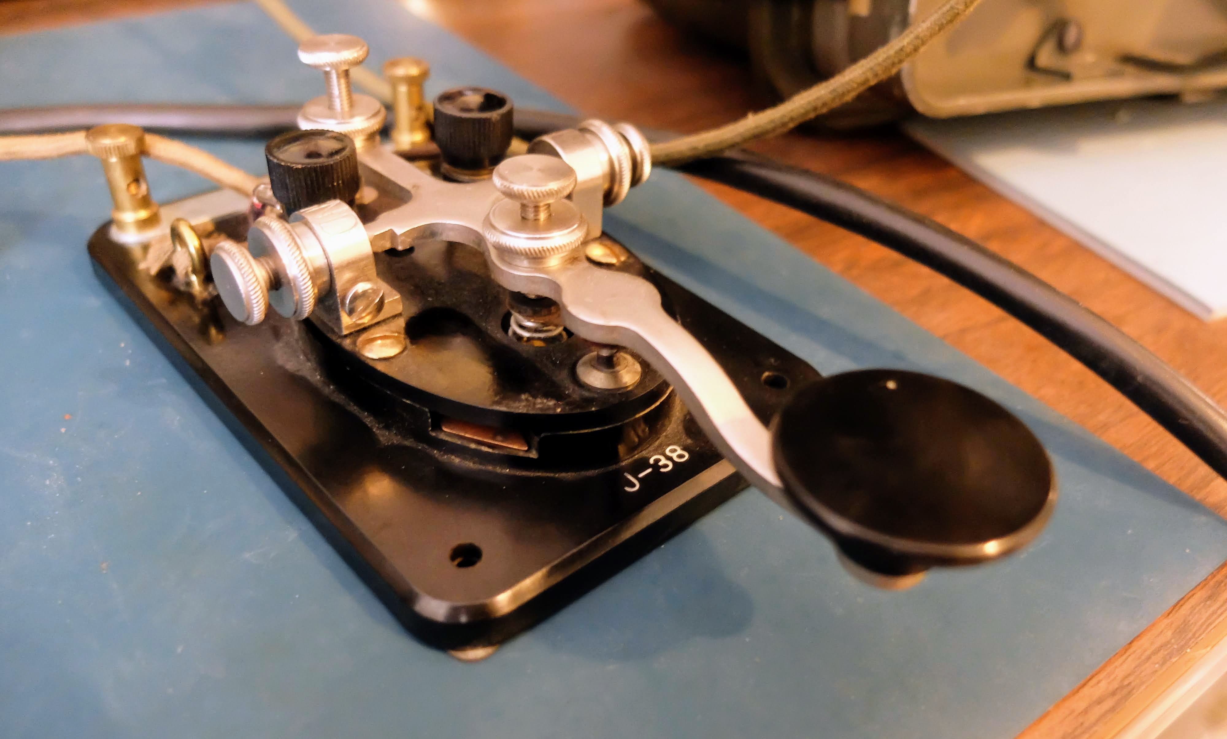
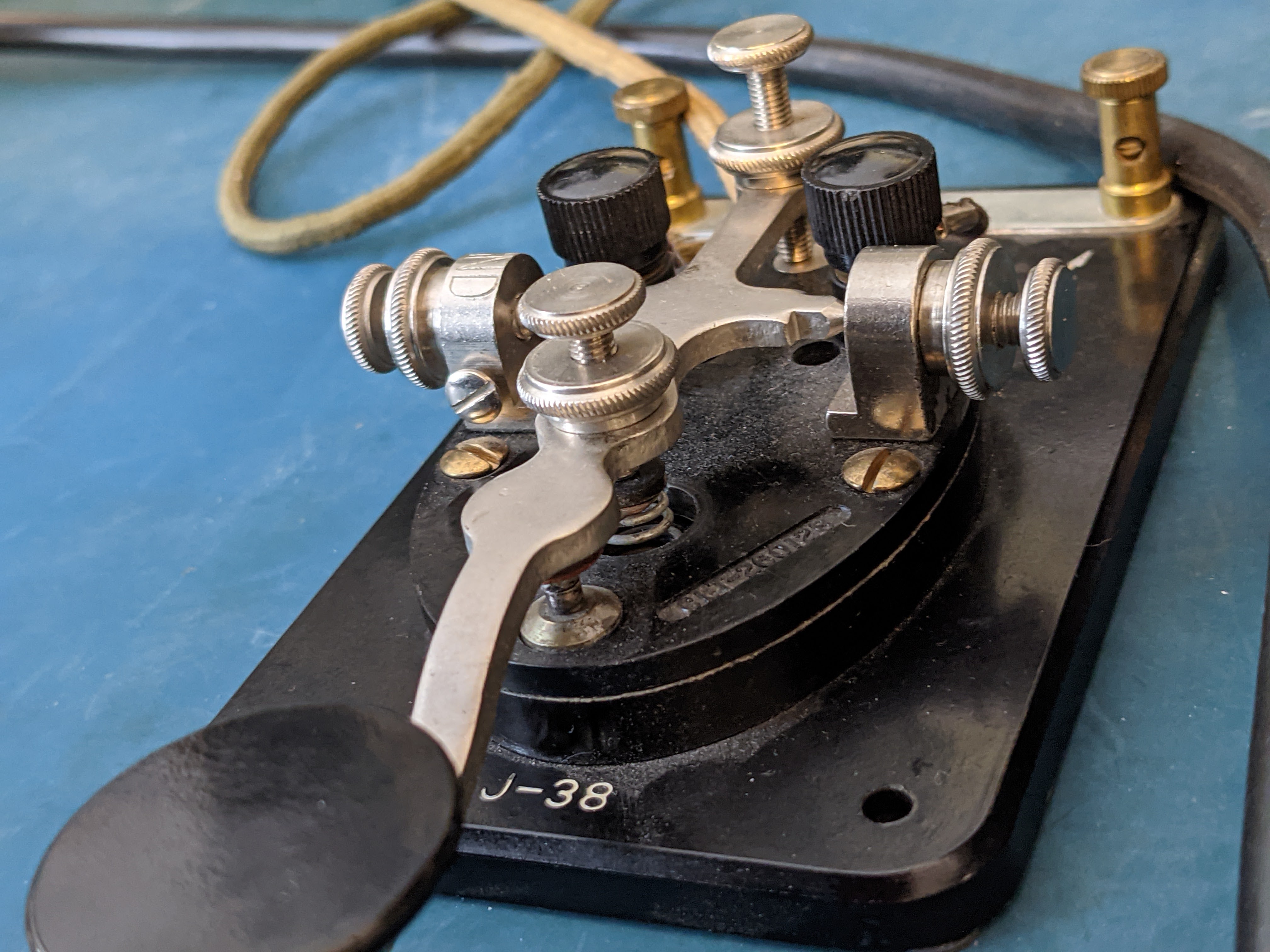
Interestingly, the RF meter peaks when the station is not at a zero-beat, so the needle cannot be used as a tuning aid. Additionally, since this radio predates built-in keyers, you’ll need an external unit or a mechanical key. The jack is wired for a standard "tip = dit" configuration.
The AF/Sidetone Conflict
My primary complaint involves the sidetone volume. In this design, the sidetone level is tied directly to the AF (audio frequency) gain control. I prefer to operate with the RF gain turned down and the AF gain turned up to manage band noise, but this makes the sidetone deafeningly loud during transmission.
Currently, I have to manually turn the AF gain down before every transmission and back up to listen. I am planning to research a modification to separate the sidetone level from the main volume control to make CW operation more practical.
Filtering and Narrow-Band Operation
This transceiver predates the era of Digital Signal Processing (DSP), relying entirely on analog circuitry and crystal filters. While the TS-830S offered optional crystal filters for CW, this particular unit is only equipped with the standard SSB crystal filter. There is no digital noise reduction or sharp audio peaking for CW signals.
What this rig does provide—which was likely a novel feature at the time—is a Variable Bandwidth Tuning (VBT) control. This allows you to linearly narrow the IF bandwidth down to approximately 500 Hz with a 6 dB slope. It is certainly not "sharp" by modern standards; even with the bandwidth dialed all the way down, I can still hear stations within 2 kHz of my frequency.
To help manage interference, the radio includes:
Adjustable Notch Filter: Useful for knocking down a specific nearby CW carrier.
IF Shift: This allows you to move the passband relative to the signal to further reject adjacent QRM.
While these controls are effective for an analog design, they are a far cry from a modern rig like my Yaesu FT-DX10. On the Yaesu, I can achieve a razor-sharp focus on a single CW signal and essentially make the rest of the band disappear. On the hybrid, you are always operating with a much wider "window" into the RF spectrum.
The things I like
Thermal management and fan noise
One thing I immediately noticed about the TS-830S is how quiet the fan is. Despite the fact that the vacuum tubes generate a significant amount of heat—essentially operating at "oven" levels—the fan is variable speed and remains very quiet even when moving a large volume of air.
I have complained about the fan noise on my FT-DX10 numerous times. Operating the Kenwood reminds me of the design choices Yaesu has made with their modern rigs; simply mounting a standard muffin fan on the back is a far less sophisticated solution compared to the integrated thermal design found in this older equipment.
Sound
The TS-830S is technically a dual-conversion transceiver utilizing two intermediate frequencies: 8.83 MHz and 455 kHz. However, its architecture differs from the traditional "Collins type" designs, like the older TS-520. In the TS-830S, the bandwidth of both IF stages is narrowed simultaneously during VBT operation. Because of this specific implementation, it essentially functions like a single-conversion transceiver with an 8.83 MHz IF.
Despite the lack of modern filtering, the receiver is very pleasant to listen to. In fact, other than the volume control issue I mentioned previously, the sidetone on this rig sounds far better than the raspy, digitized sidetone on my Yaesu FT-DX10.
The audio out of the case is excellent. It has a very good speaker that is well isolated, and can go to high volumes without distorting. The case itself has felt / damping materials where edges mate with other panels, to reduce resonance. It is nicely designed. Speaking of the case itself, it is thick metal. Not car ramp thick, but sturdy, not bendy.
There is a definite appeal to switching off the modern SDR rigs and their "super-filtered" audio. Sometimes it’s worth returning to a simpler design that down-converts RF to the audible range without sending the signal through light-years of digital processing before it reaches your ears.
Little things
Conclusions
AI Analysis of Logs for Antenna Directionality
Where is this dang thing pointing?

I have made a lot of contacts when portable but I paper log those and they rarely make it back into my electronic logs, so nearly all of these logs are from my station operation and 95% of those have been on the 80m OCF.
Gemini provided me with this evaluation
- 80m: Broad "figure-8" pattern with maximum radiation broadside to the wire at 55° (NE) and 235° (SW).
- 40m: A "four-leaf clover" pattern. Your strongest performance is at 45° and 315°, perfectly hitting Europe and the US Midwest.
- 20m: Four sharp lobes that pull closer to the wire axis. Your log shows high-gain "spikes" at 35° (Europe) and 330° (West Coast).
- 10m: Eight or more very narrow lobes. Your 10m contacts are extremely directional, primarily clustering at 50° and 130°.
- 80m, Broad Figure-8, Strongly Biased NE/SW: Contacts cluster at 55° and 235°. Coverage is broad but noticeably stronger toward the Northeast US/Canada. High: Matches the broadside radiation of a dipole.
- 40m, 4-Leaf Clover, 4 Strong Peaks: Contacts are highly concentrated at 45°, 135°, 225°, and 315°. You are successfully hitting Europe and the US West Coast via these distinct lobes. Very High: Confirms the 2nd harmonic pattern.
- 30m, Distorted 6-Lobe, NW Dominant: You have a massive cluster toward the Northwest (330°). This band is notoriously asymmetrical on an OCF antenna, and your log shows you've "found" the dominant lobe. Moderate: The theoretical pattern is messy; your data simplifies it.
- 20m, 4 Long, Sharp Lobes, Sharp Spikes: Contacts are extremely localized at 35° (Northern Europe) and 330° (Washington/Oregon). This matches the narrowing of lobes as frequency increases. High: Matches the "tilting" of lobes toward the wire axis.
- 17m, 6 Very Sharp Lobes , Strategic Clusters: Contacts cluster at 13° (New York/New England) and 225° (Mexico). The narrowness of these clusters indicates you are operating within high-gain "fingers" of radiation. High: Confirms the 5th harmonic pattern.
- 10m, 8+ Needle-Thin Lobes, Pinpoint DX: You have specific, isolated successes at 50° and 130°. Many other directions show "nulls" where no contacts were made. Moderate: High-QSB (fading) makes this band less predictable.
Conclusions
I did look at some tools for evaluating directionality based on logs such as https://qsomap.org but the ones I found are visual and require manually evaluating the graphics. There are likely other tools that would do what the AI is doing but I'm not aware of them yet. Please leave a comment if there are log analysis tools that you use for this purpose.
Loop on Ground (LoG) Receive Antenna
Dirt Shark Antenna
How a Humble Wire on the Ground Can Transform Your Radio Listening
My Noisy, Old-Faithful 80m OCF
Receive Only Antennas?
- Magnetic loops- Too fiddly to re-tune when you change bands
- Beverage - Give me land, lots of land
- LNA augmented, phased verticals - Money, money, money
- Loop on Ground - Cheap, but they can't possibly work
Loop on Ground Antenna
How to Make One


Results
Signals are being picked up by the LoG that are lost in the noise and are invisible on the waterfall of the FT-DX10 no matter how much I fiddle with the display gain and display peaking filters. But I can work them when I find them because that 80m OCF is a good performer as a TX antenna.
Conclusion
"Now I see" said the blind man
Begali Intrepid
The Perfect Bug?

A New Design
- The pendulum hinge is at the rear of the key rather than the middle
- The adjustments are all based on magnets rather than springs
- The dwell for the dits has a real control, rather than using various pieces of foam, string or clips to change dwell time
- The dit contact is a sprung plunger that always remains centered on the contact rather than brushing against it at various angles
- The split lever mechanism operates at the center of the key placing the DAH and DIT contacts much closer to one another than a traditional bug
- There is less mass in the pendulum itself than a Vibroplex Bug
- It has a sprung, nylon wheel damper that doesn't clatter
- It weighs a TON (well about 6 lbs) and feels welded to the desk without having to use non-slip material or using spit to semi glue them in place (yech, yes I use spit to hold my keys to my desk)

Preparing for Use

In Use


Conclusions?

The Endurance of CW in Amateur Radio
CW Spans a Century

 |
| Radio Telegrapher School for Enlisted Specialists 1921 |
What other modes have remained as popular standards using standard ham equipment and continuously in use by amateur radio operators as CW?
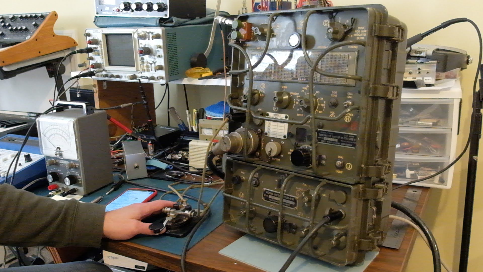
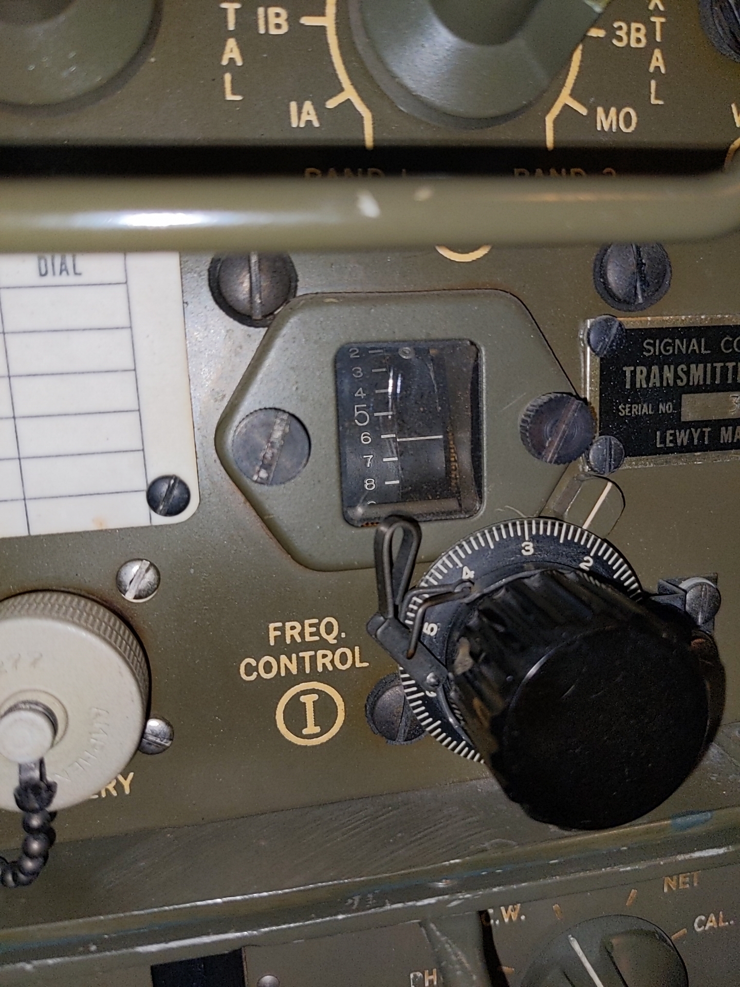
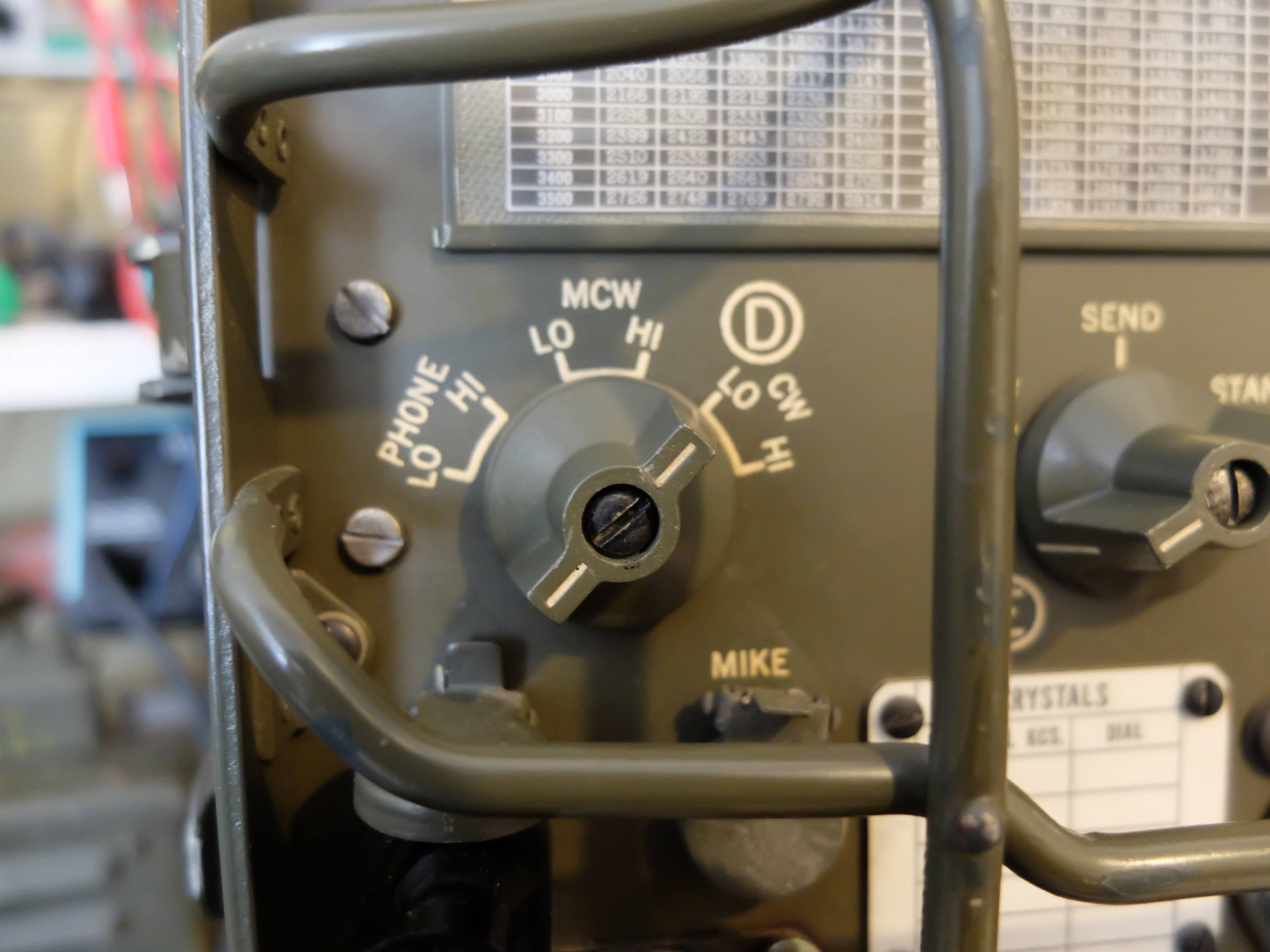
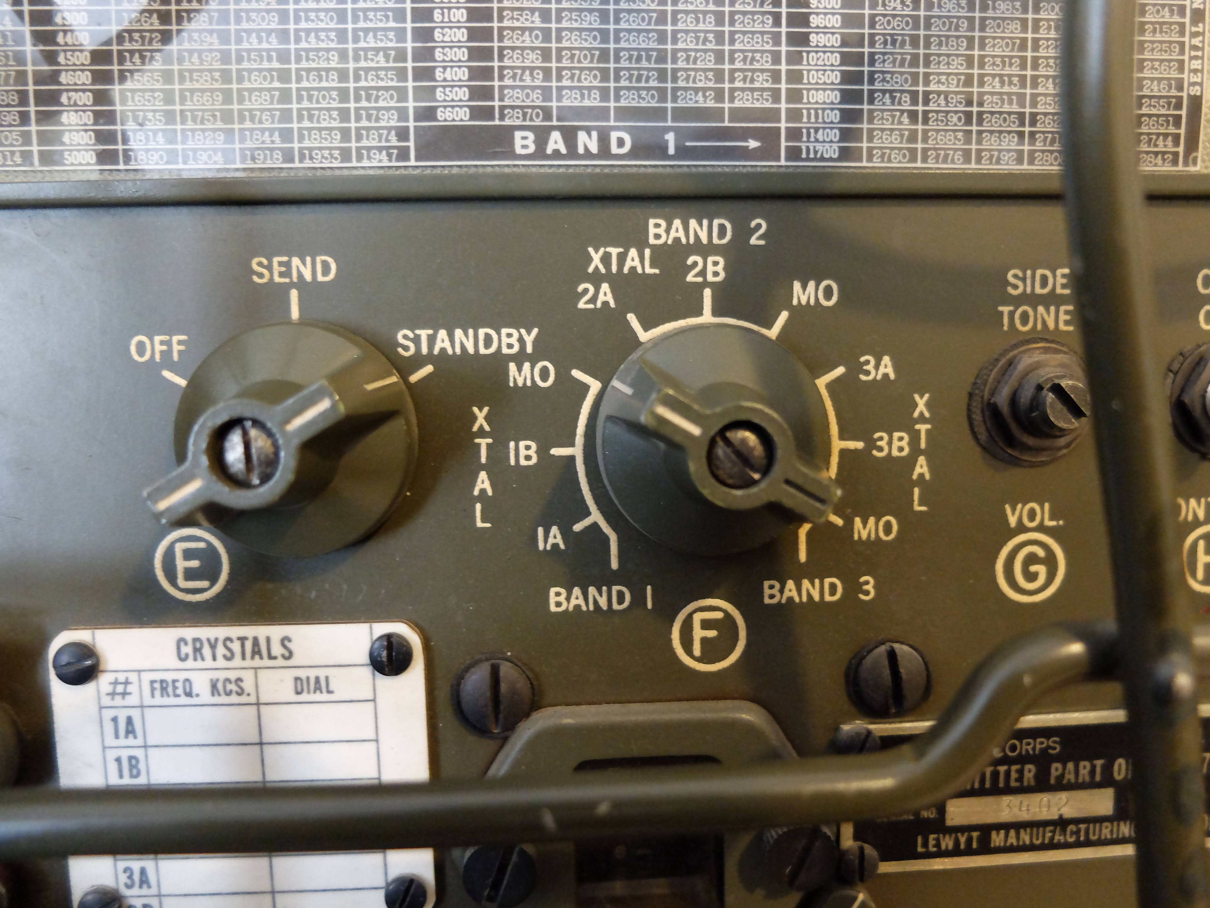
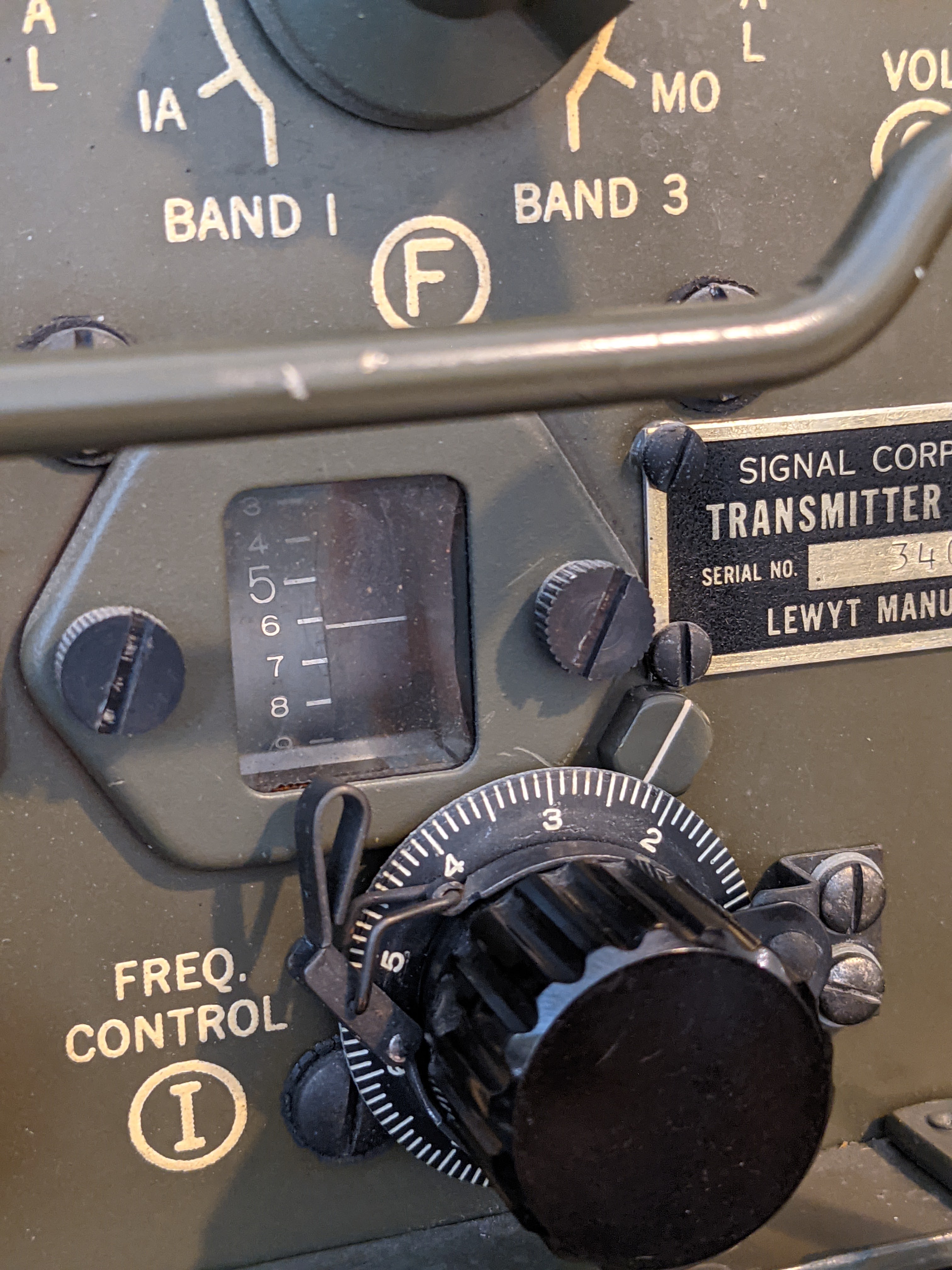
AN/GRC-9 aka “Angry Nine”
AN/GRC-9 - Long lived military comms
 |
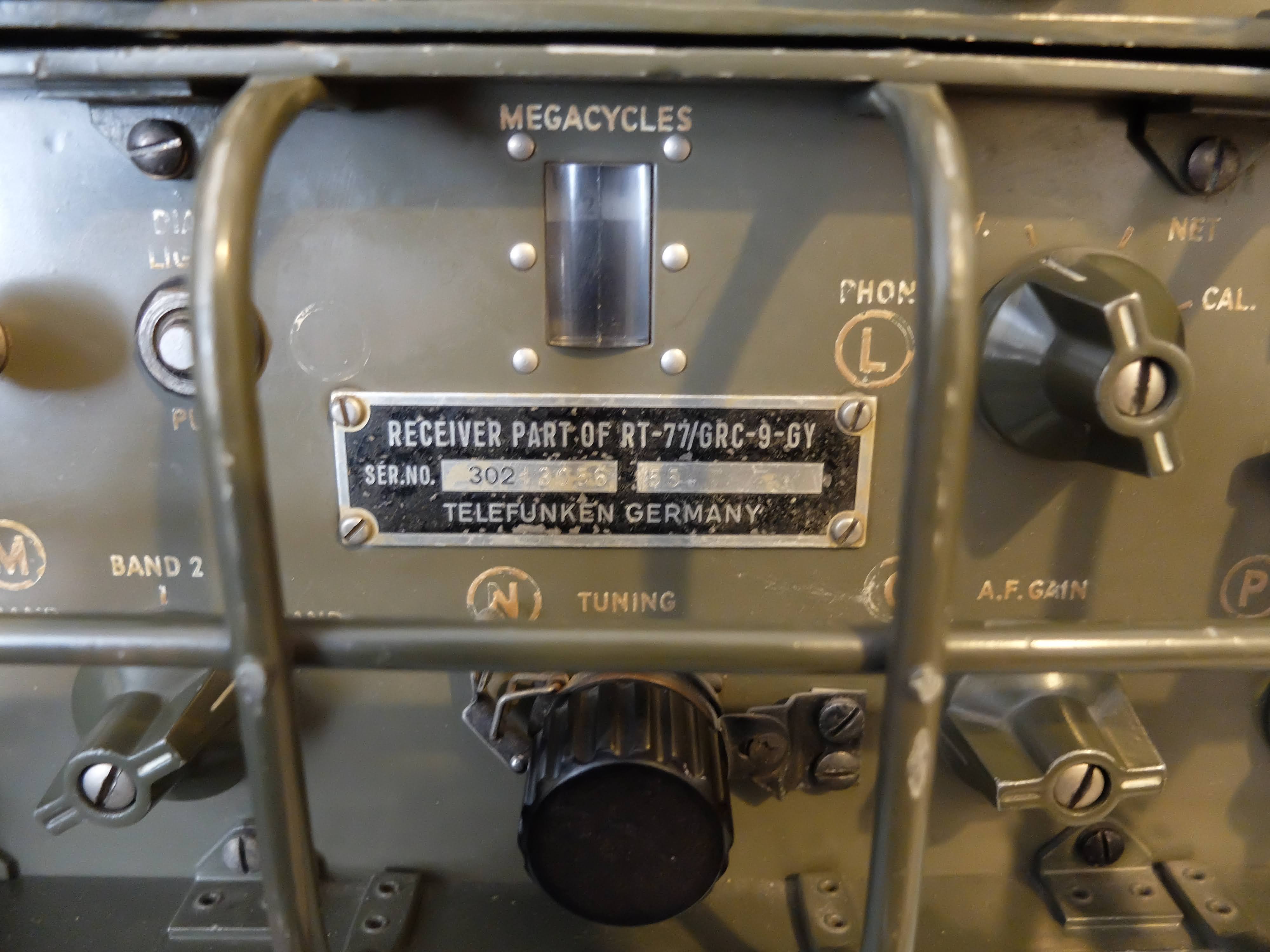
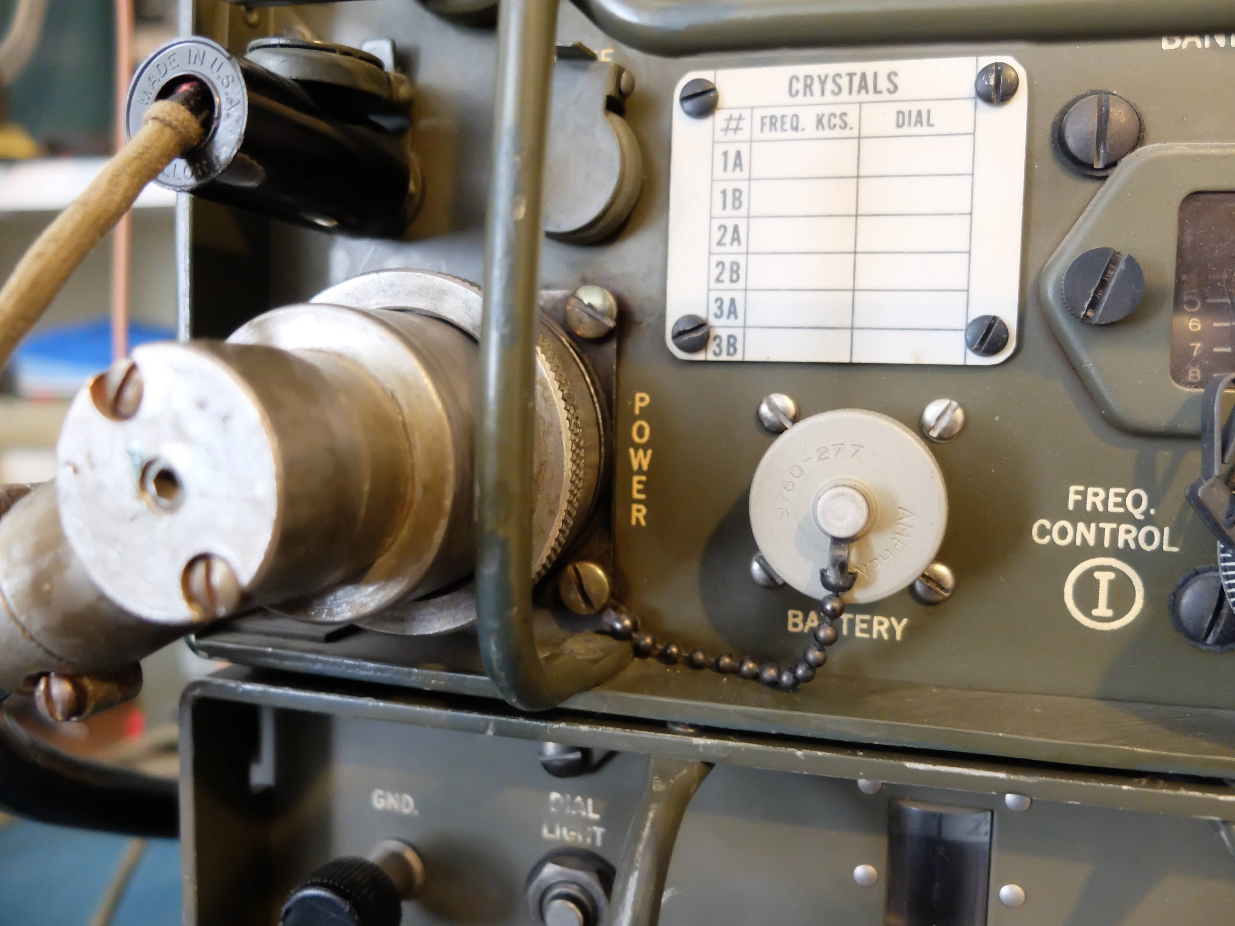
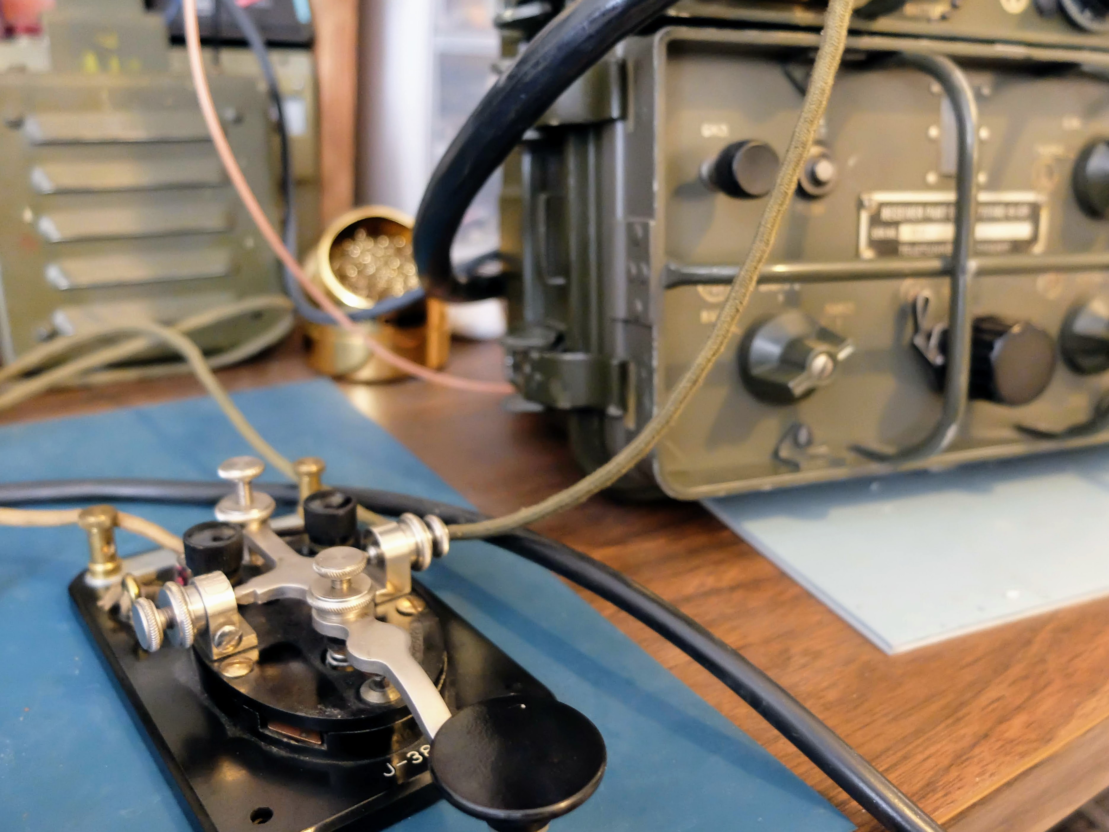
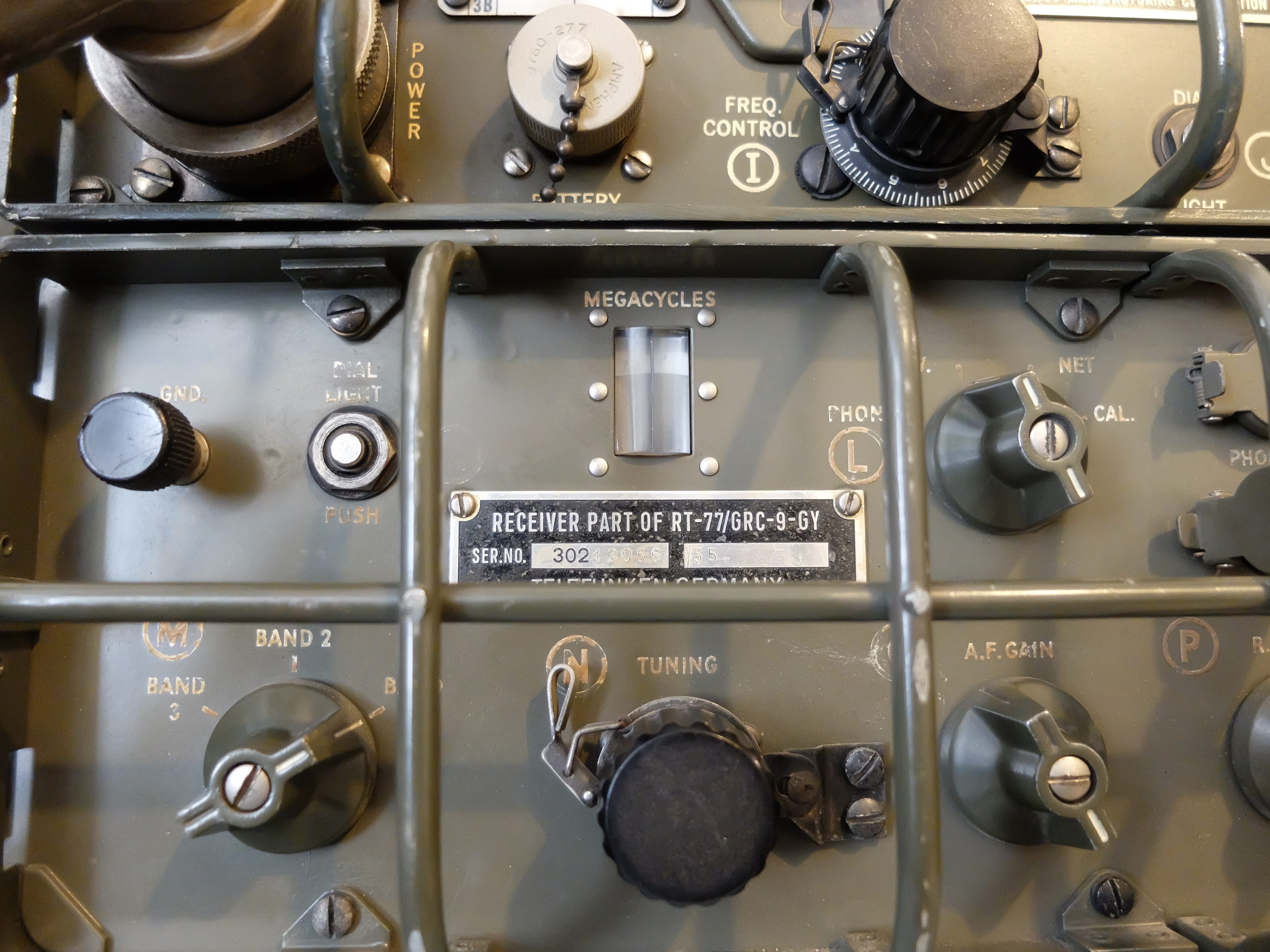
| My lovely (and radioactive) RT/77-GRC/9 |
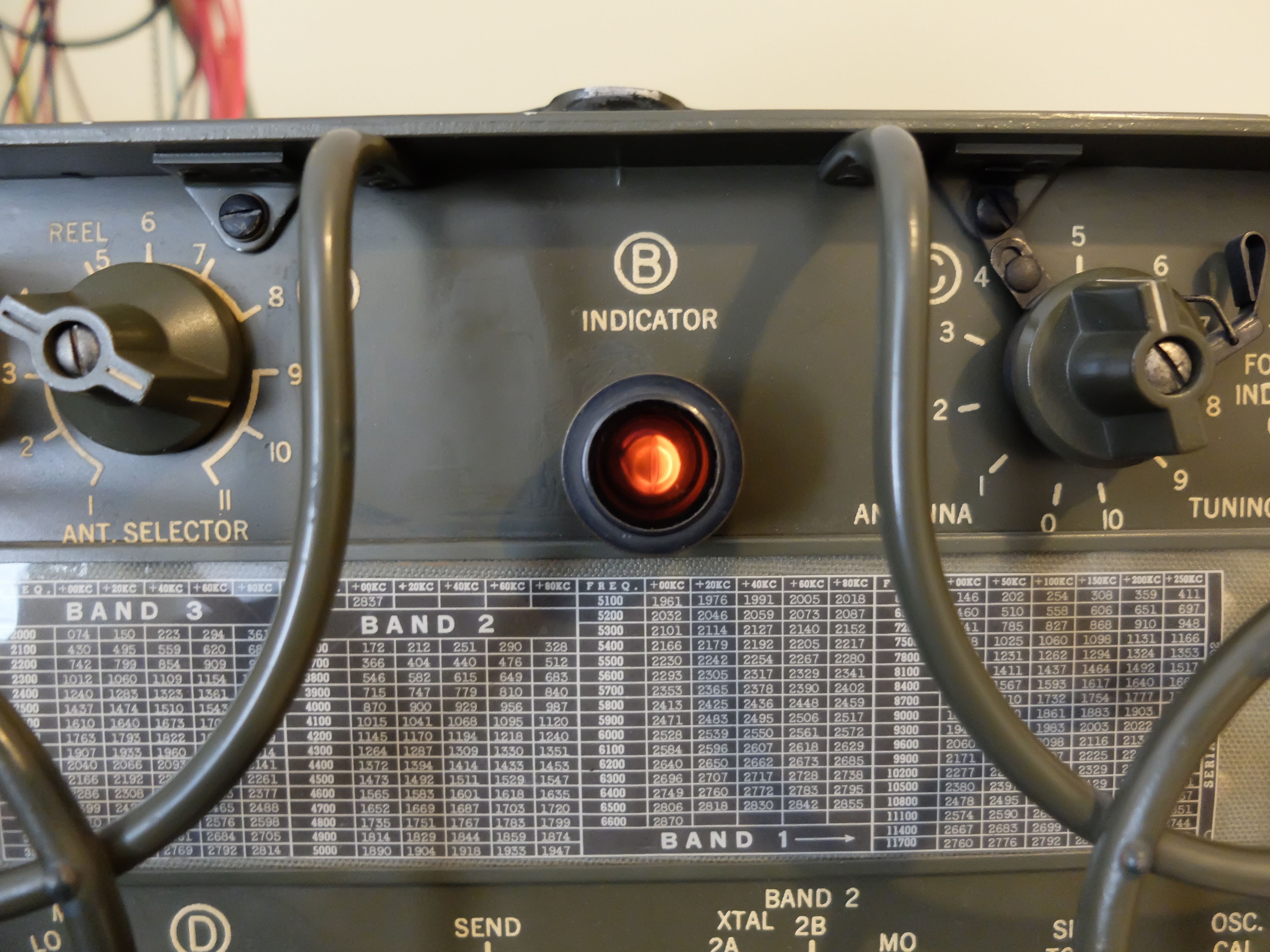
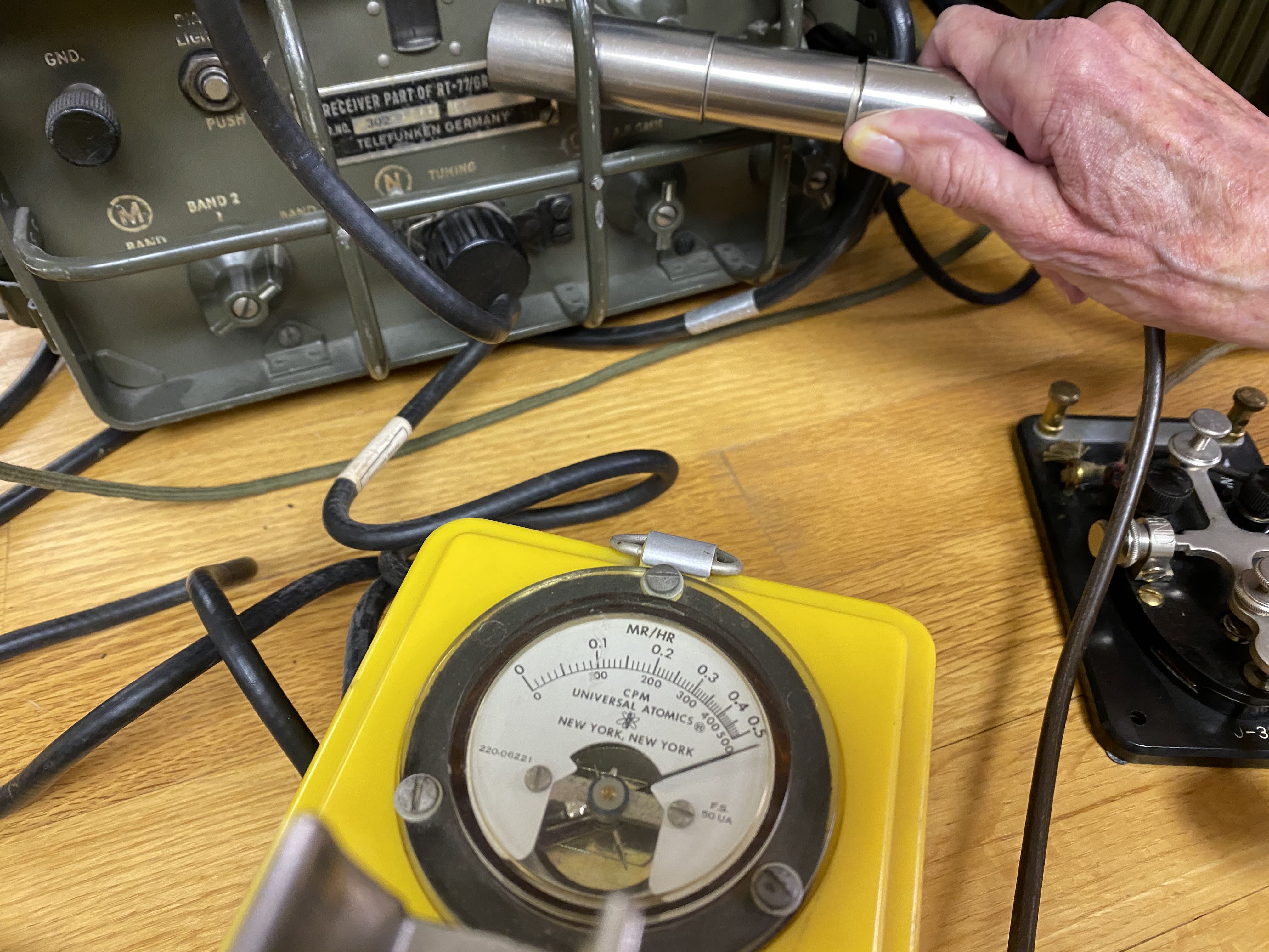 |
| Hot receiver, in more ways than one |
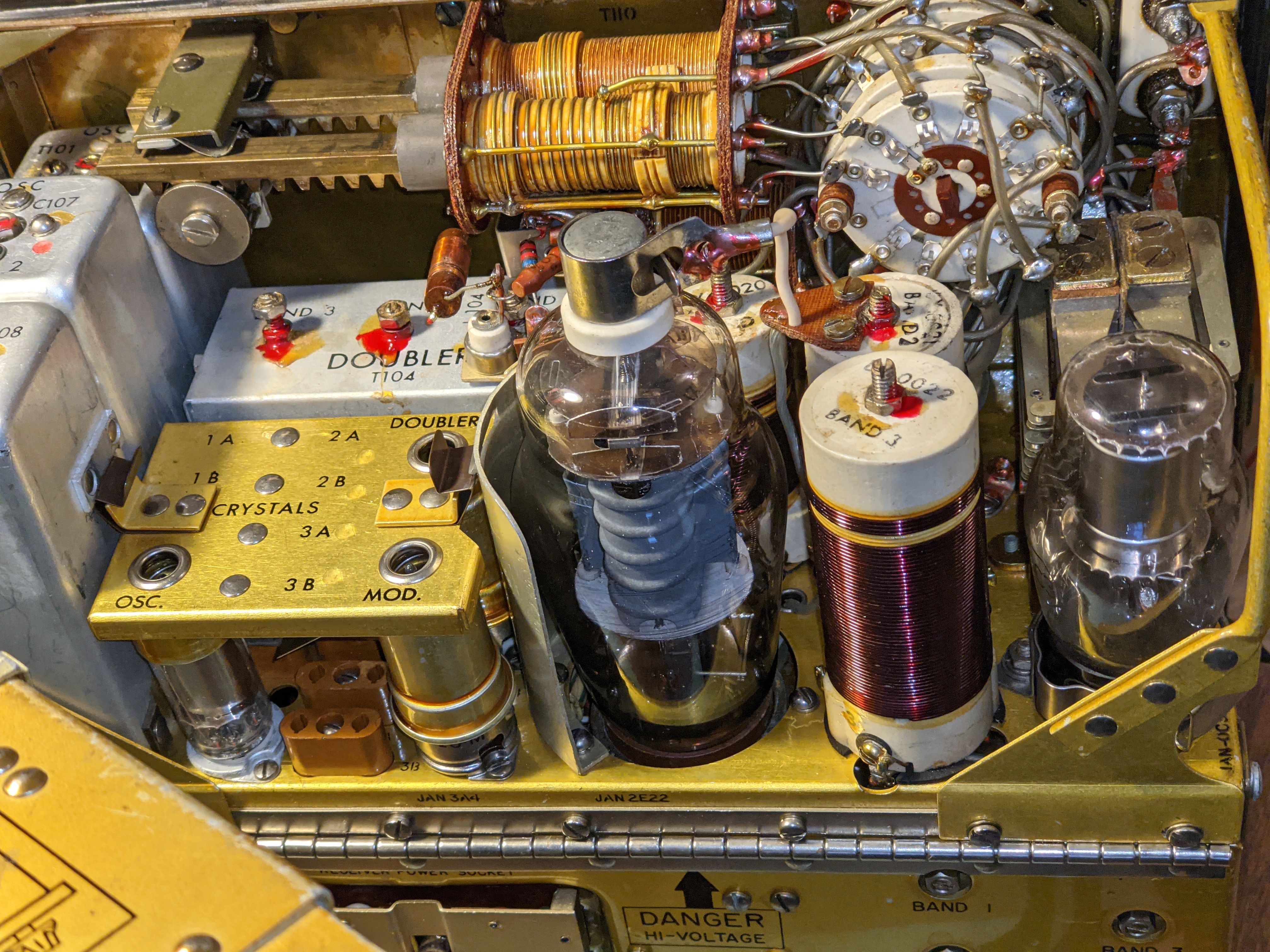
 |
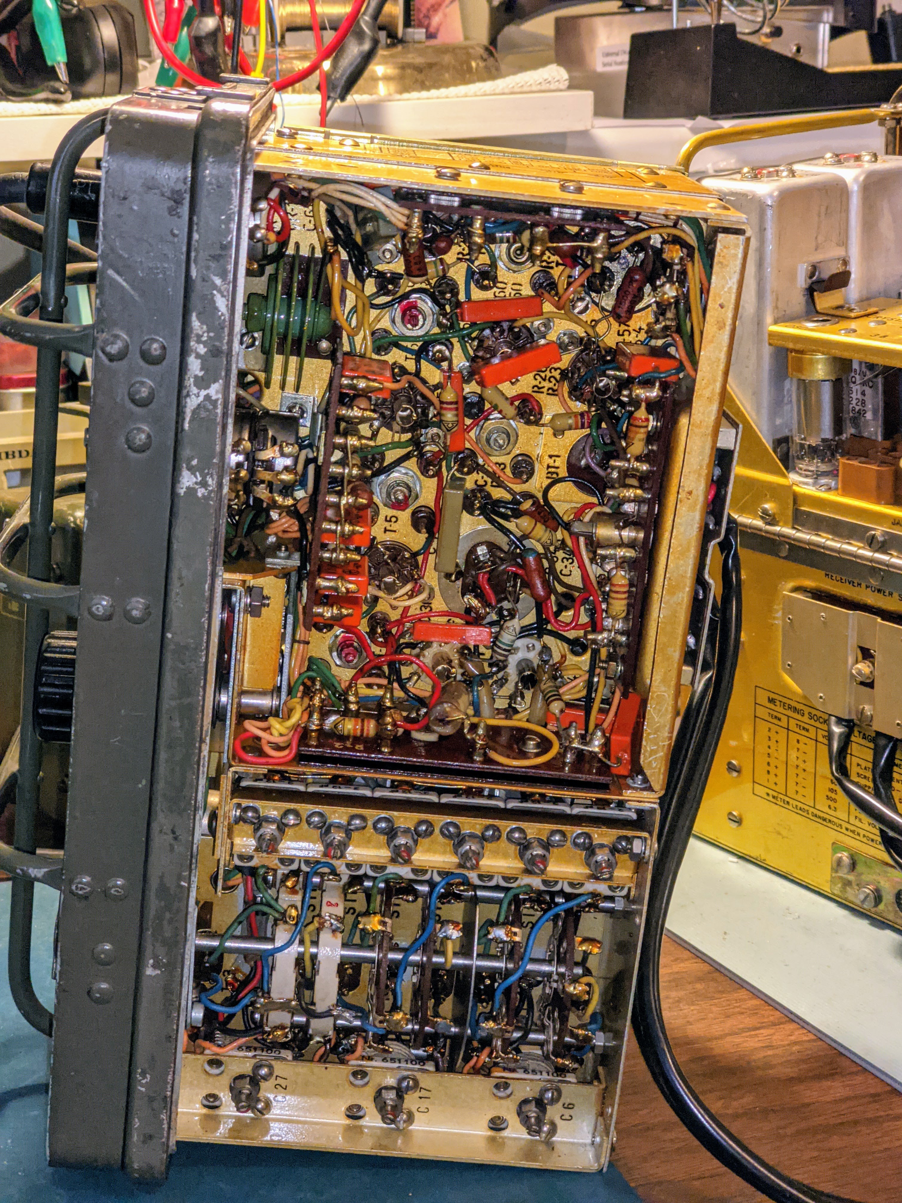
| Out of the case, tracing a low B+ power problem |

Power on the move
- Transmitter Plates -- 475 - 580 v @ 100ma
- Transmitter Filaments -- 6.5 - 6.6 v@ 2 amps
- Receiver Plates -- 105 - 120 v @ 45ma
- Receiver Filaments -- 1.35 - 1.5 v @ 500ma
- Keying Relay -- 6.0 - 6.9 v @ 575ma
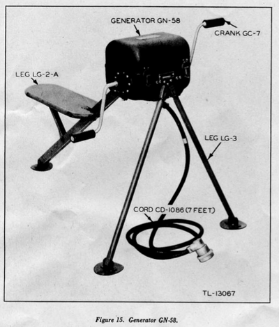
That's a tall order for mobile and portable power supplies but designers in the 1940's were quite clever in packing power supply units. I managed to obtain both the hand cranked GN-58 generator with the base chassis and seat for portable operations, and a DY-88 for fixed / mobile operations.
DY-88 mobile power supply
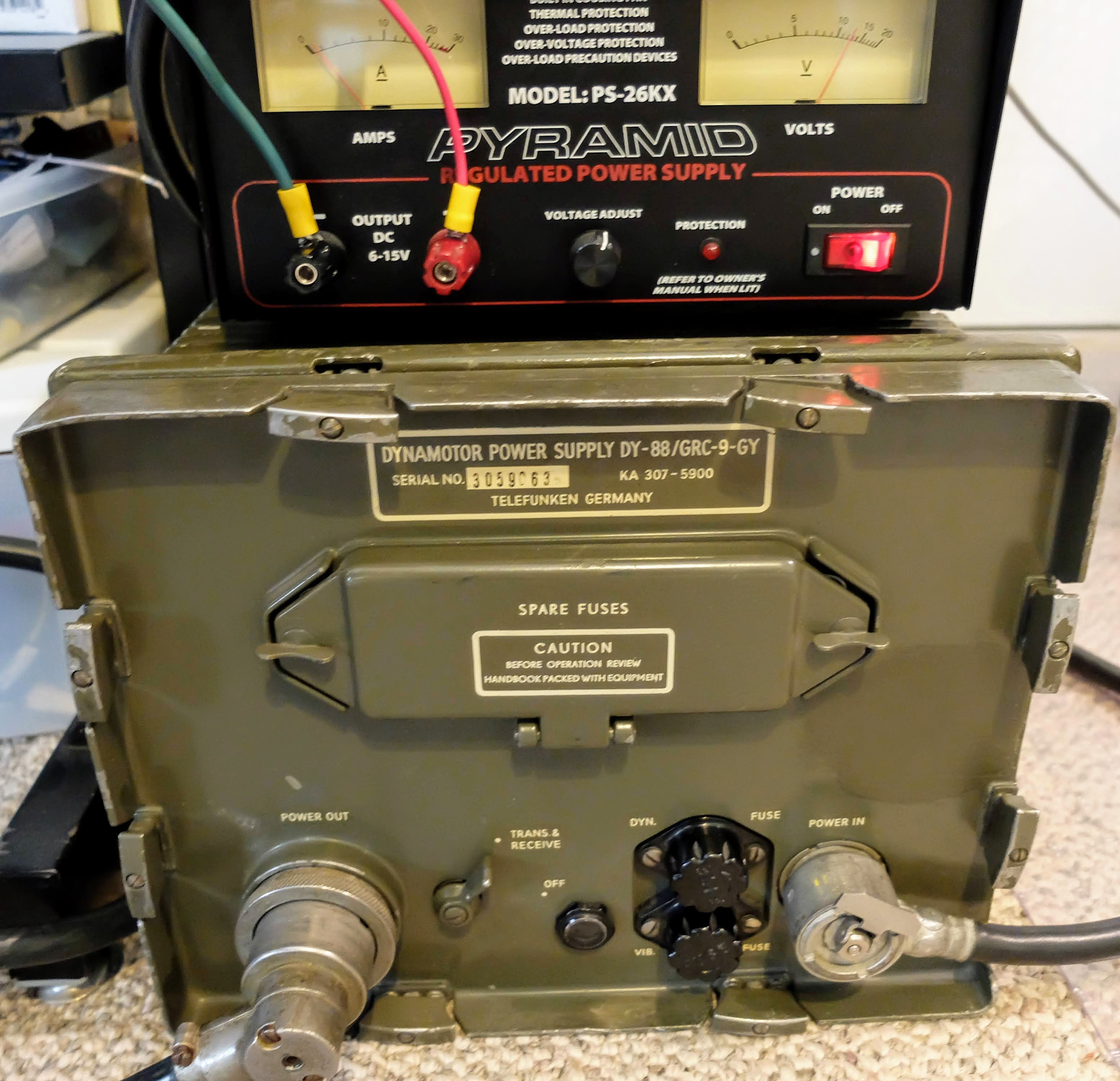 |
| DY-88 set to 12v powered by Amateur 12v supply |
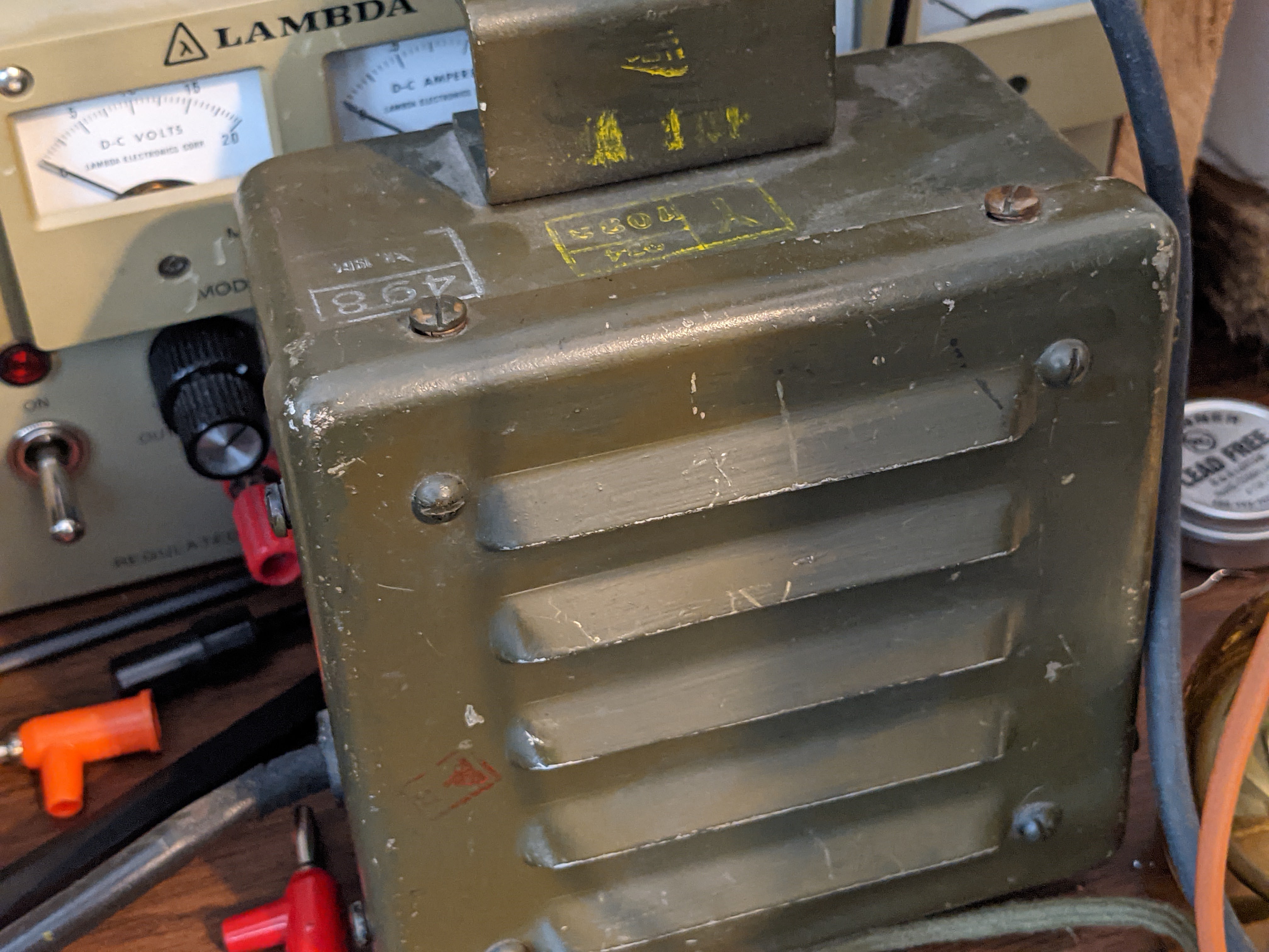
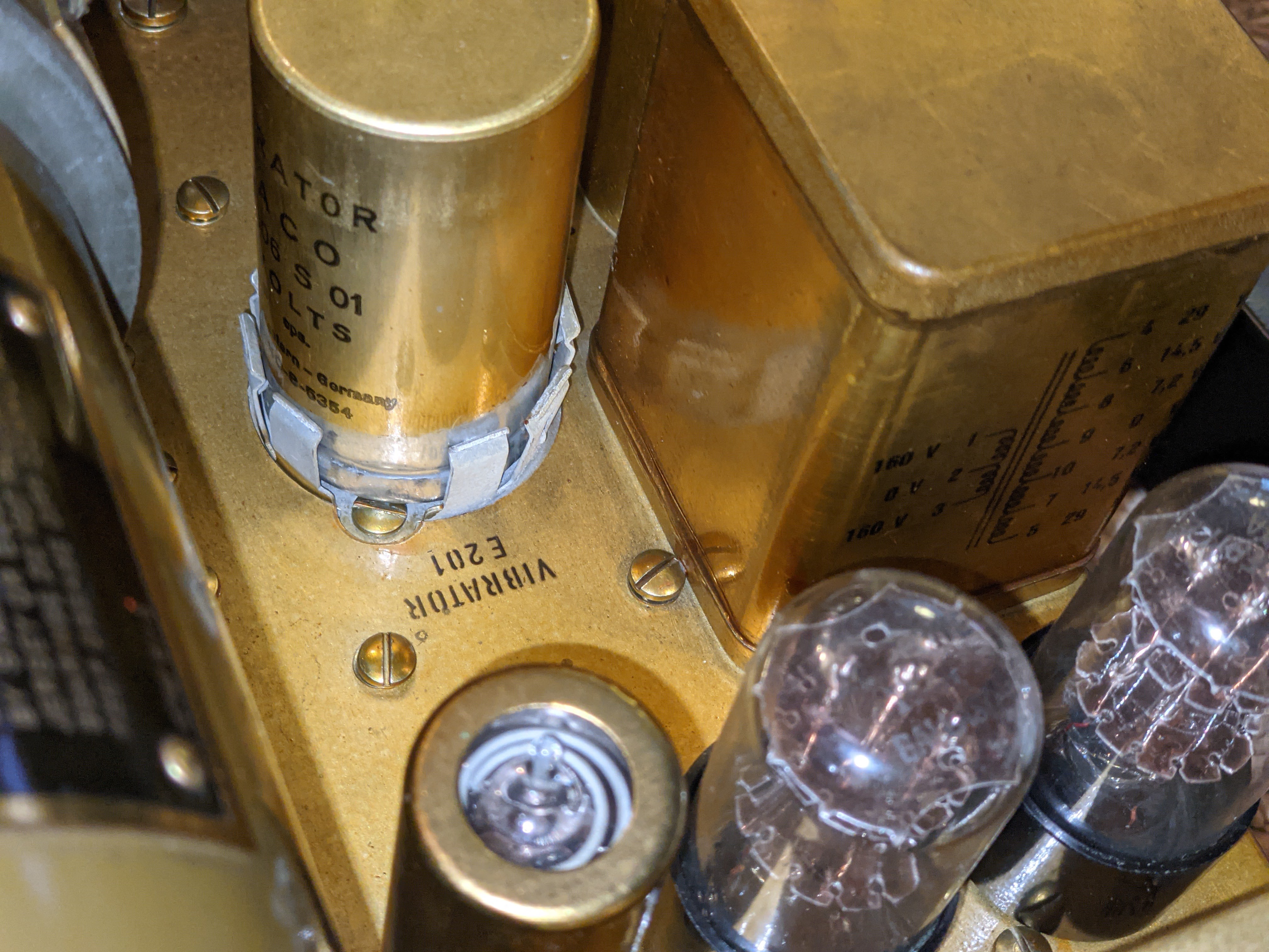
 |
| Vibrator power supply for low B+ |
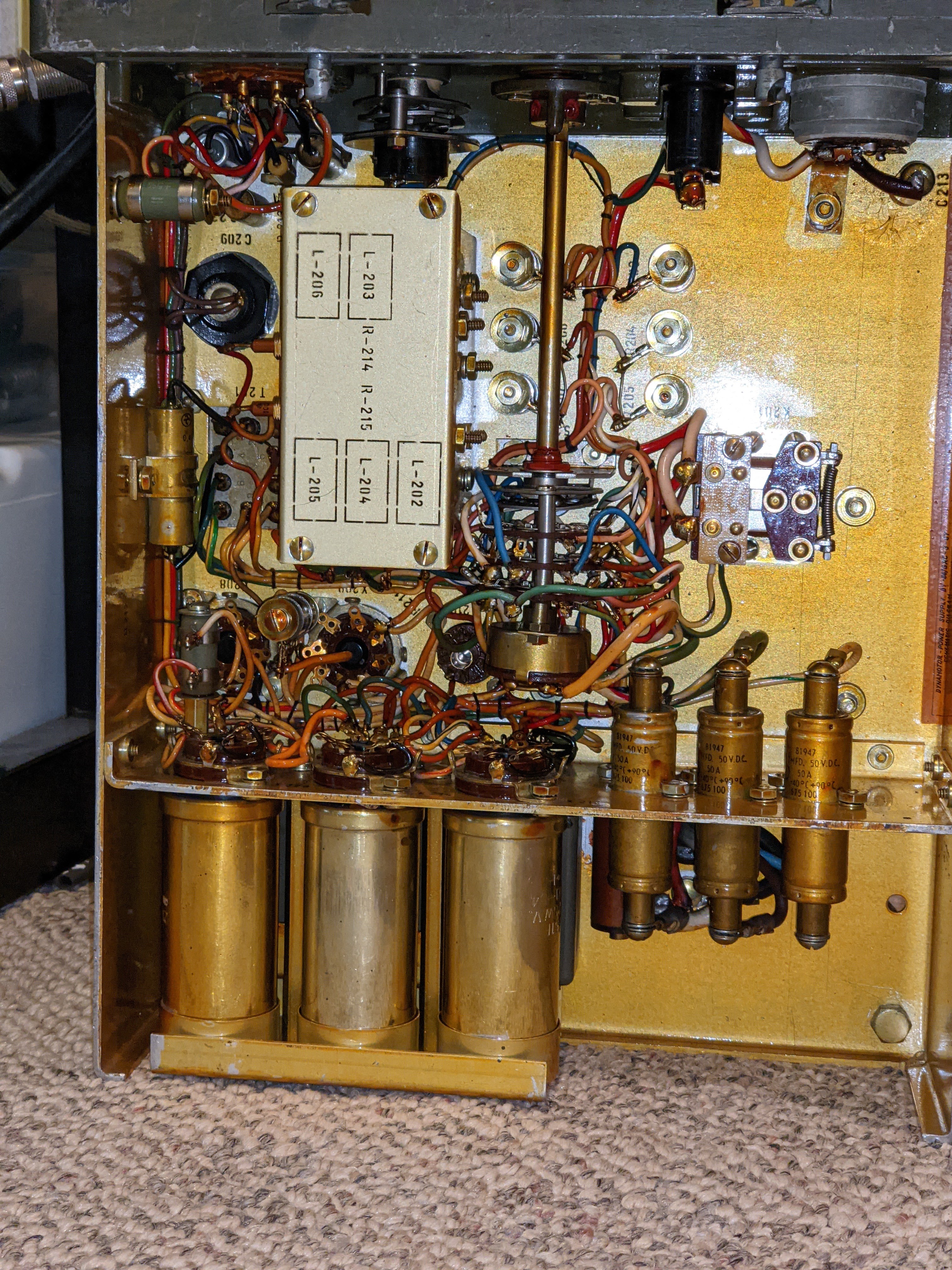 |
| Power filtering |
I supply the DY-88 from either an RV battery or an amateur 12v power supply. When in Standby the DY-88 draws less than 1 amp, but placing the radio in Send mode switches on the Dynamotor which draws 12 amps @12v, without key-down and up to 14 amps on high-output key-down. It will drain an RV battery pretty quickly at that rate if the radio is left in Send mode, and works an amateur power supply pretty hard as well. So don't expect to operate remote off a battery alone for too long if your having lengthy QSOs. An added benefit of the DY-88 is that when the enclosed Dynamotor is running you'll have a nice extra 85 dB of generator noise to accompany your listening pleasure.
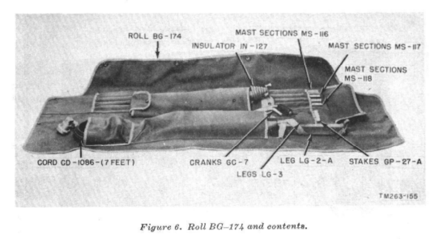
GN-58 portable field hand-cranked power supply
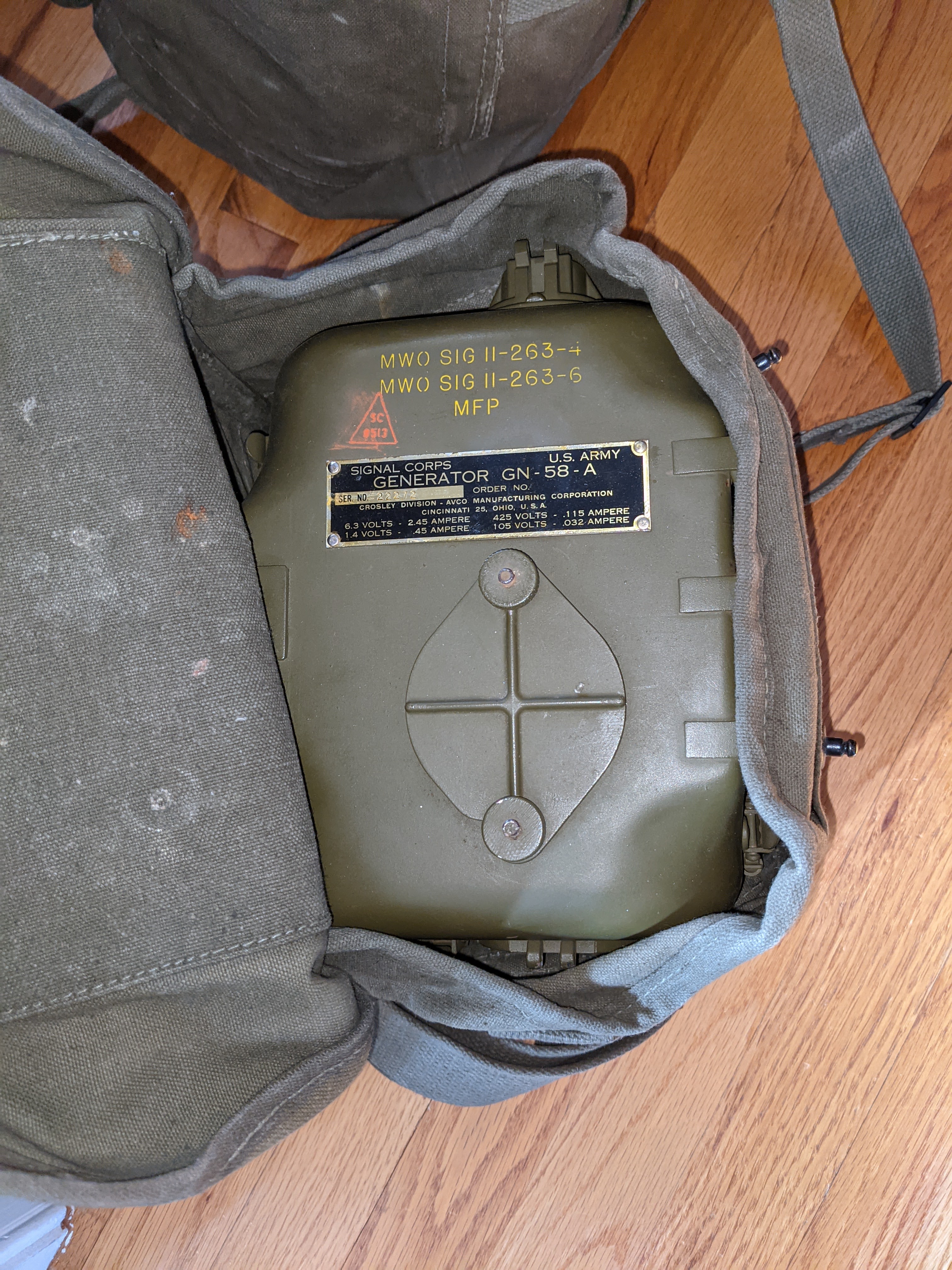 |
| Generator head in carry bag |
 |
| NOS Shiny |
 |
| Deployed |
If you have a BC-48 battery hooked up then your human power supply can pause cranking while your receiving. I have a BC-48 battery enclosure that has been gutted of the original, long-dead material and replaced with 10x 9v batteries in series for the low B+ and two D-Cell batteries in parallel for the receiver filament supply.
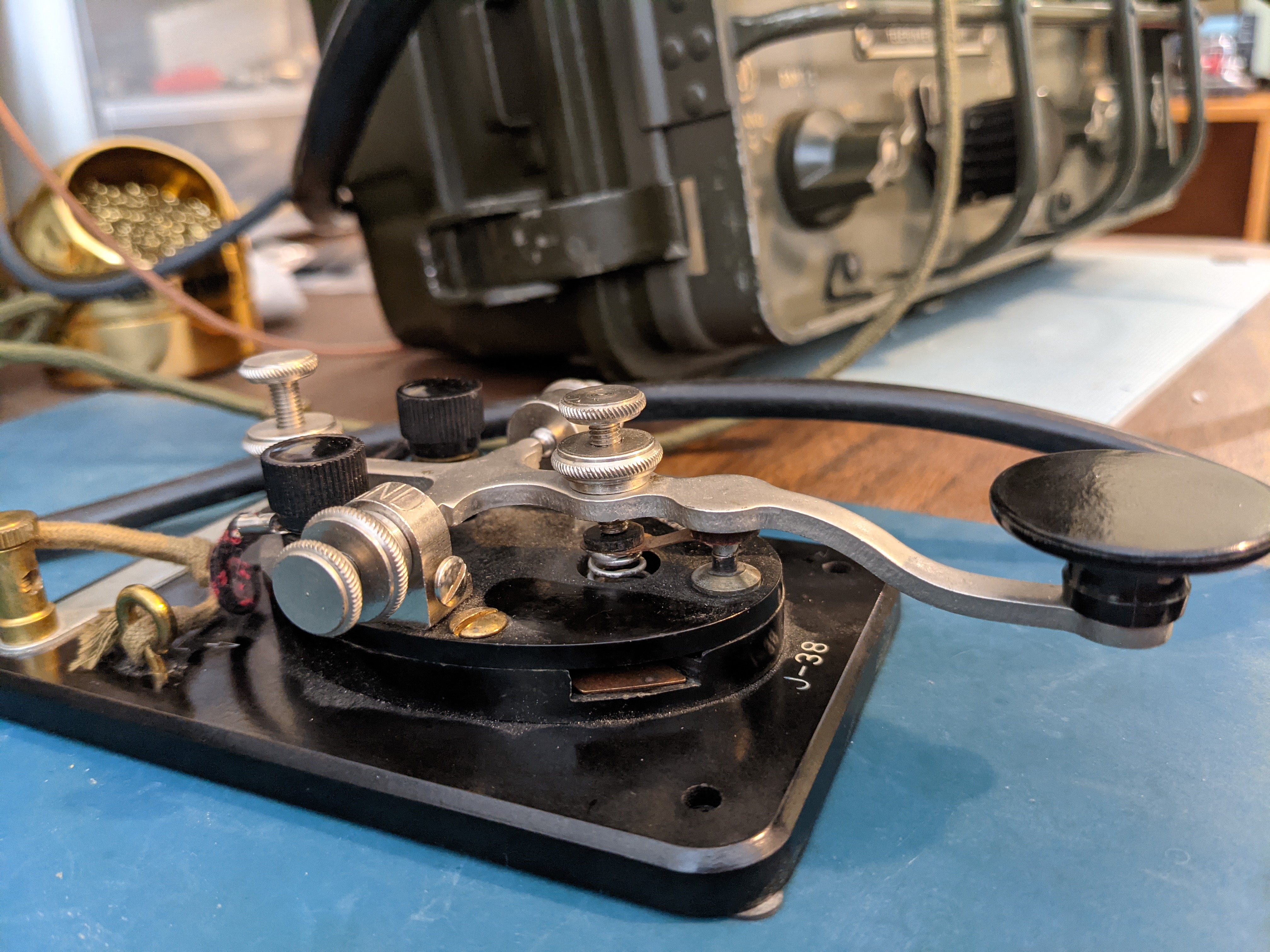
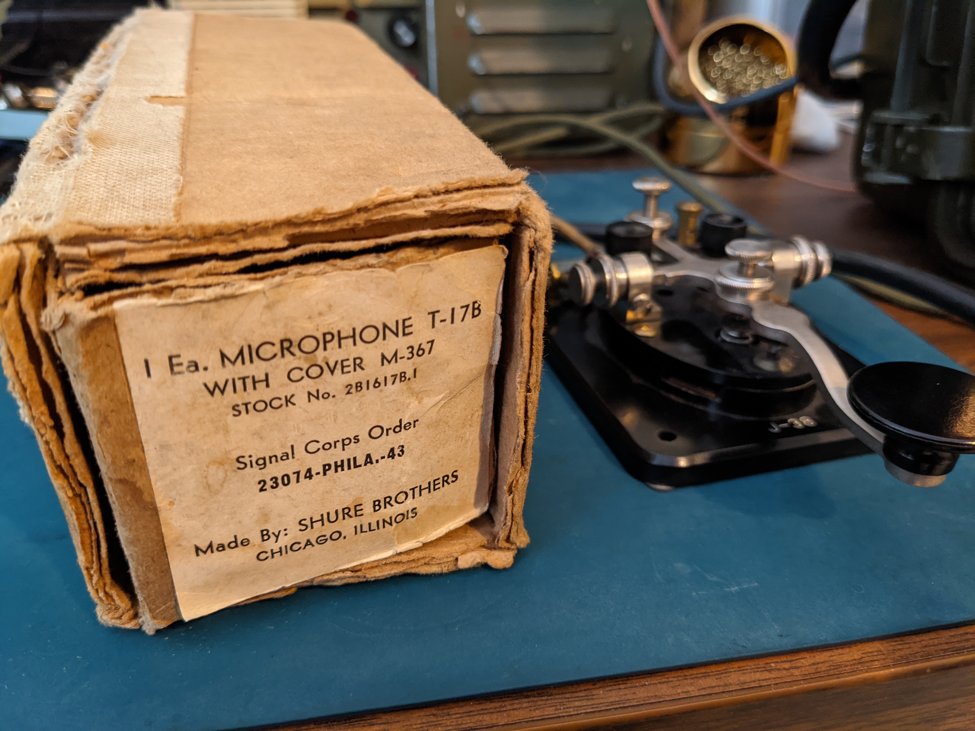
Accessories
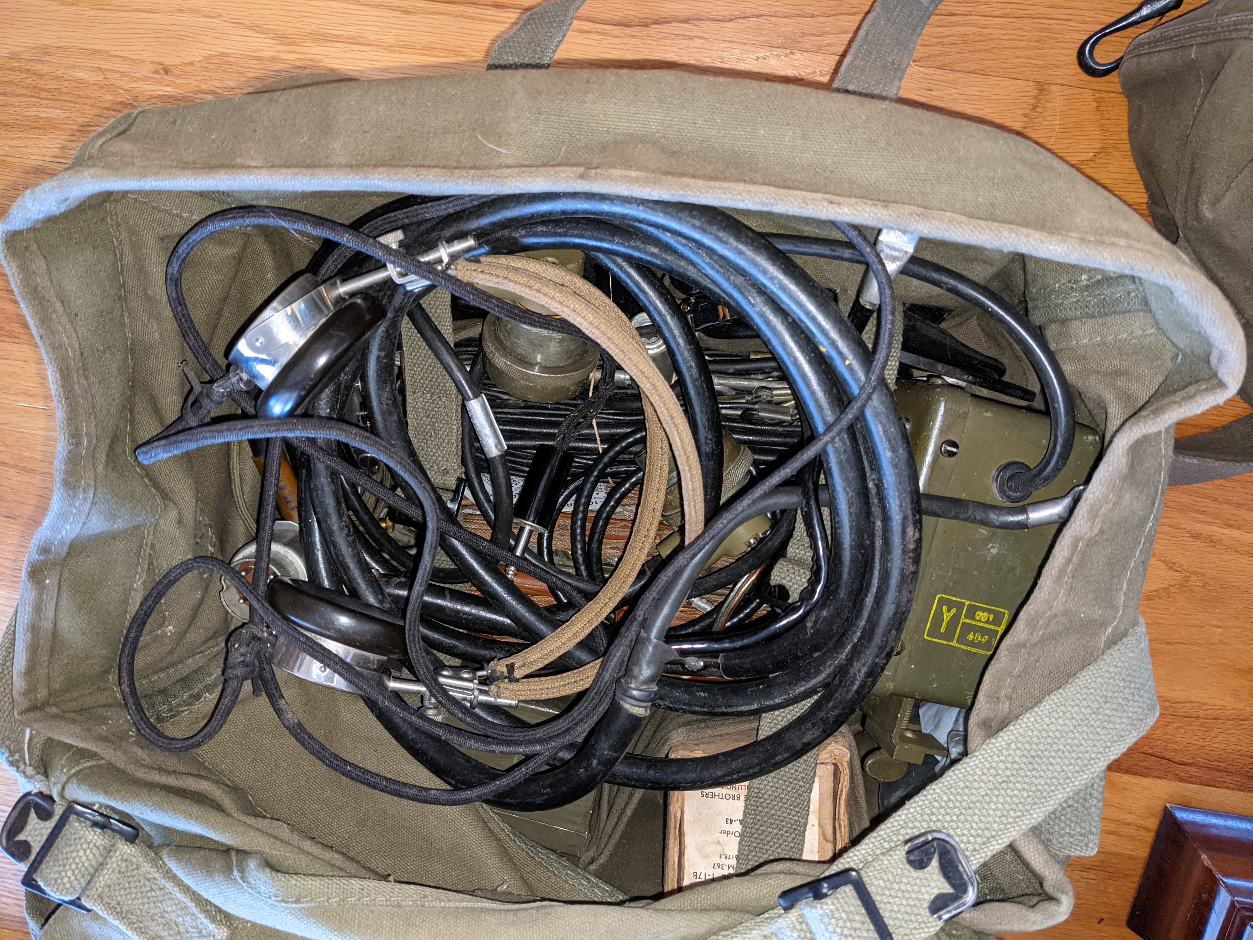 |
| Bag of goodies |
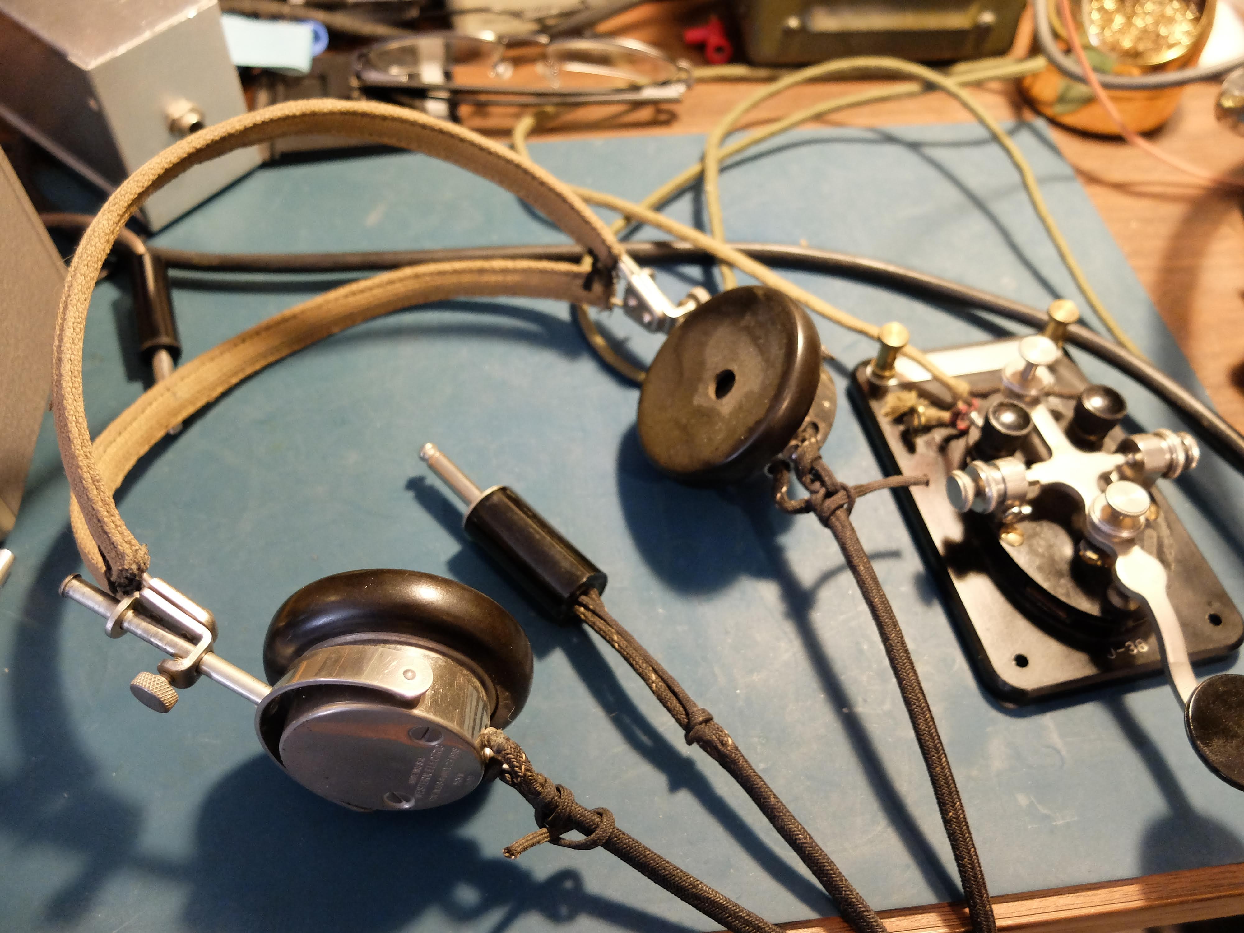
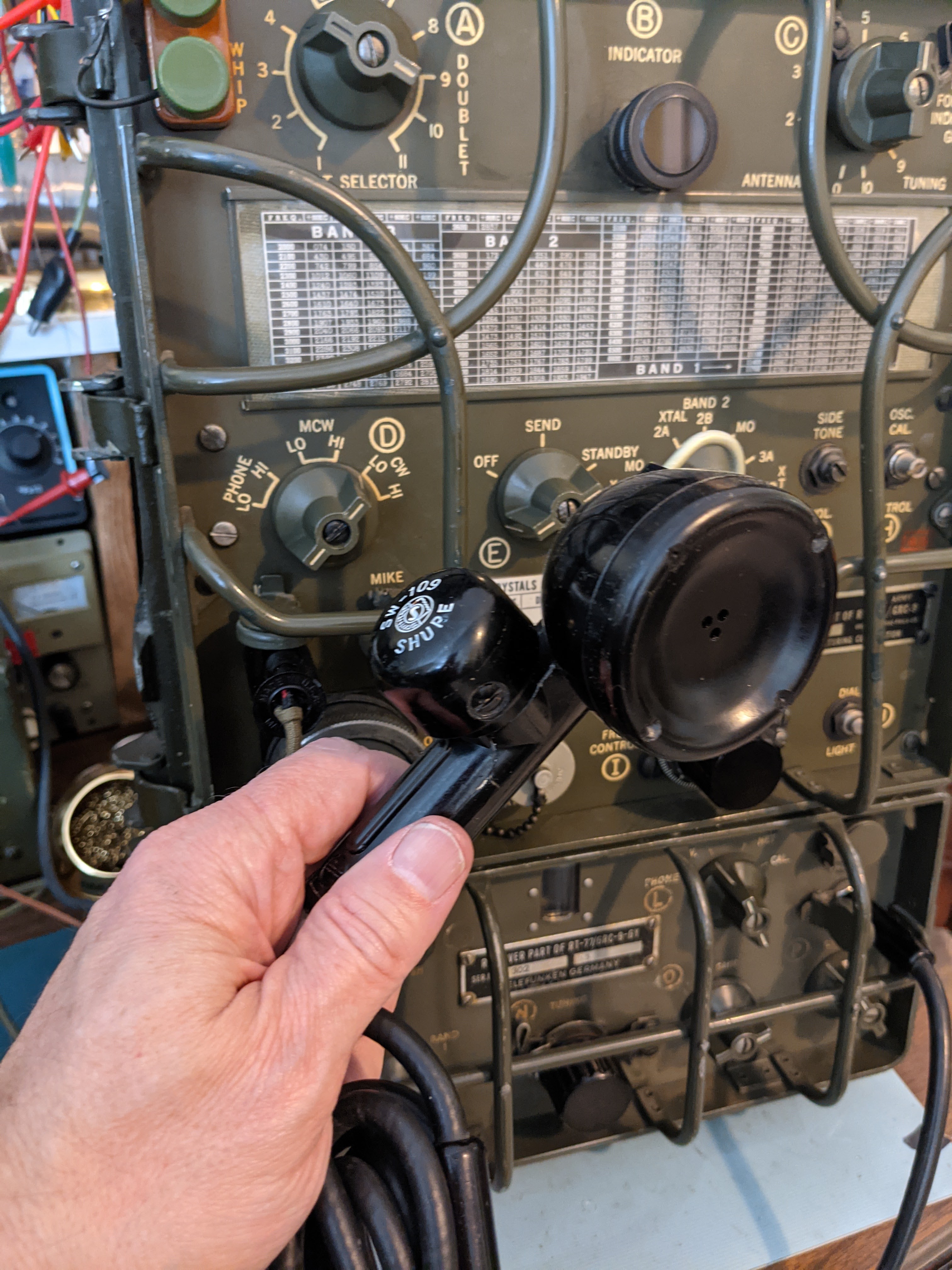
Headphones

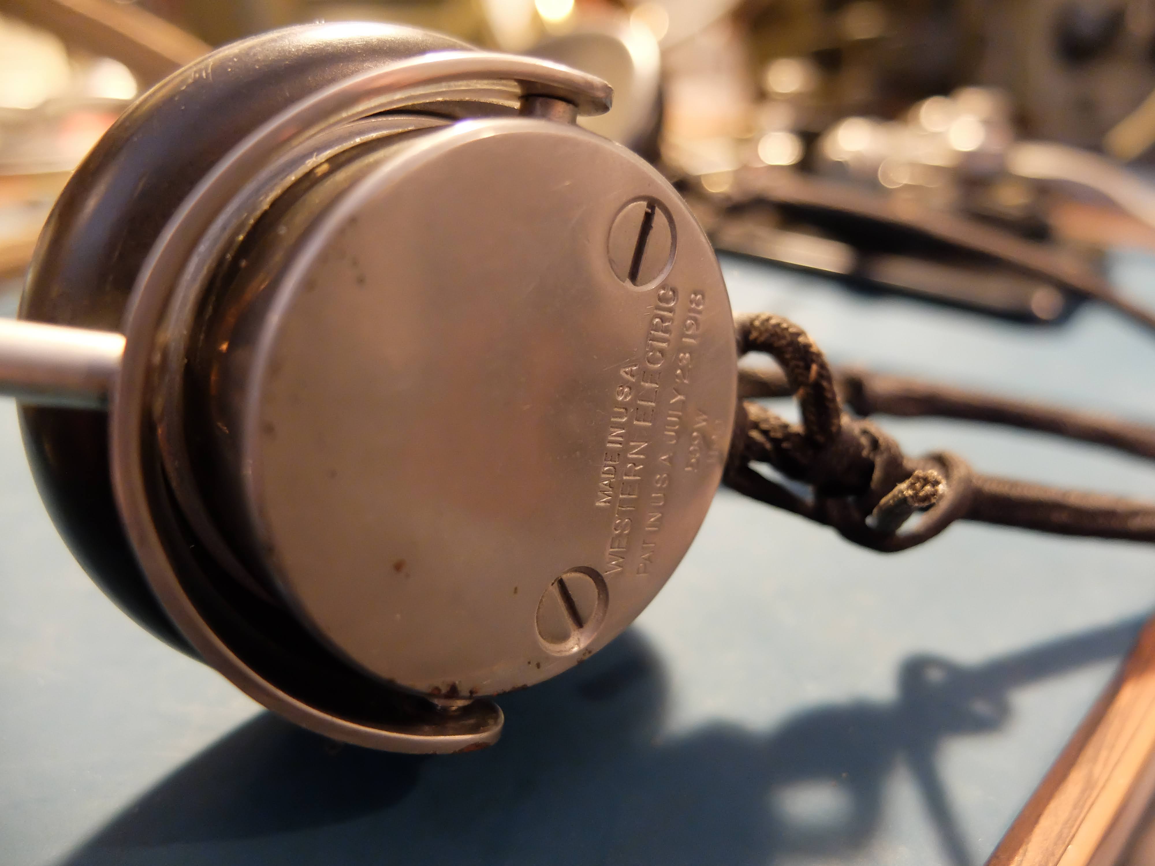
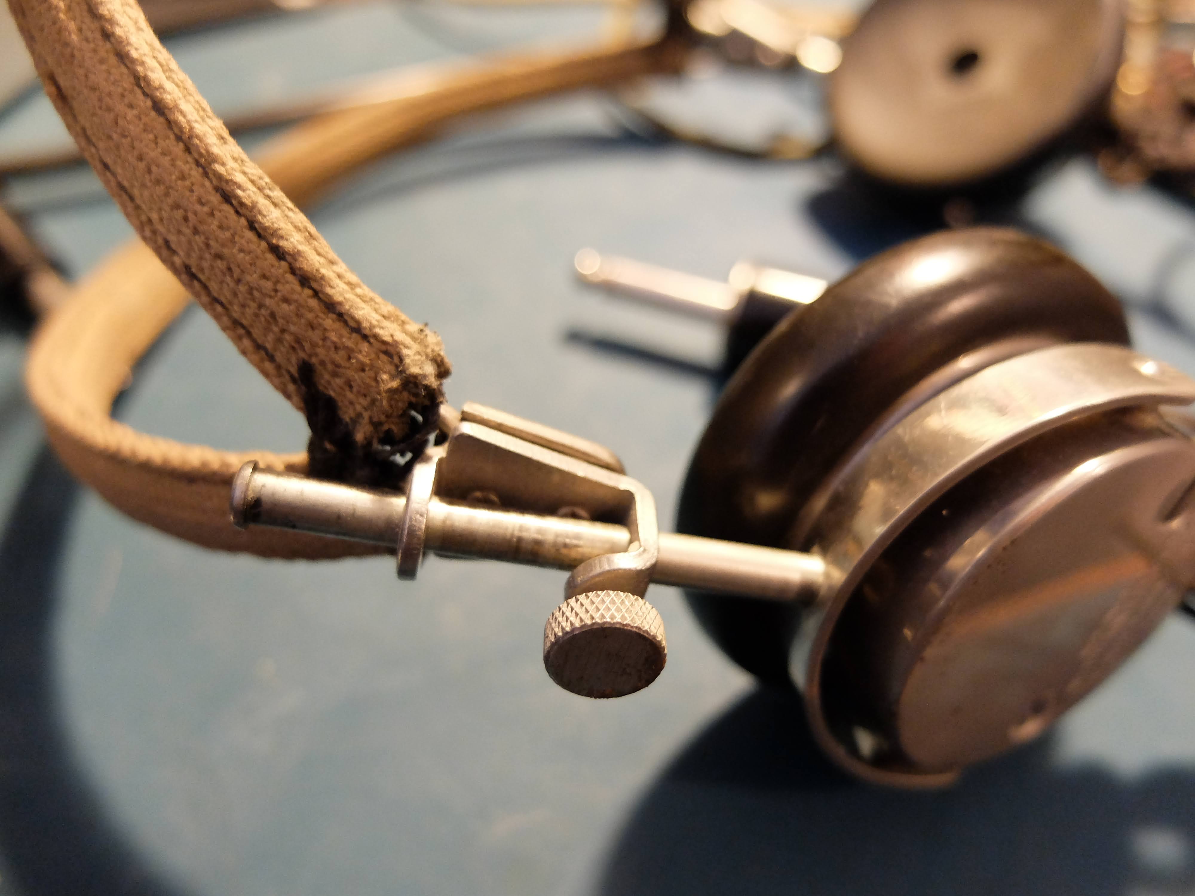

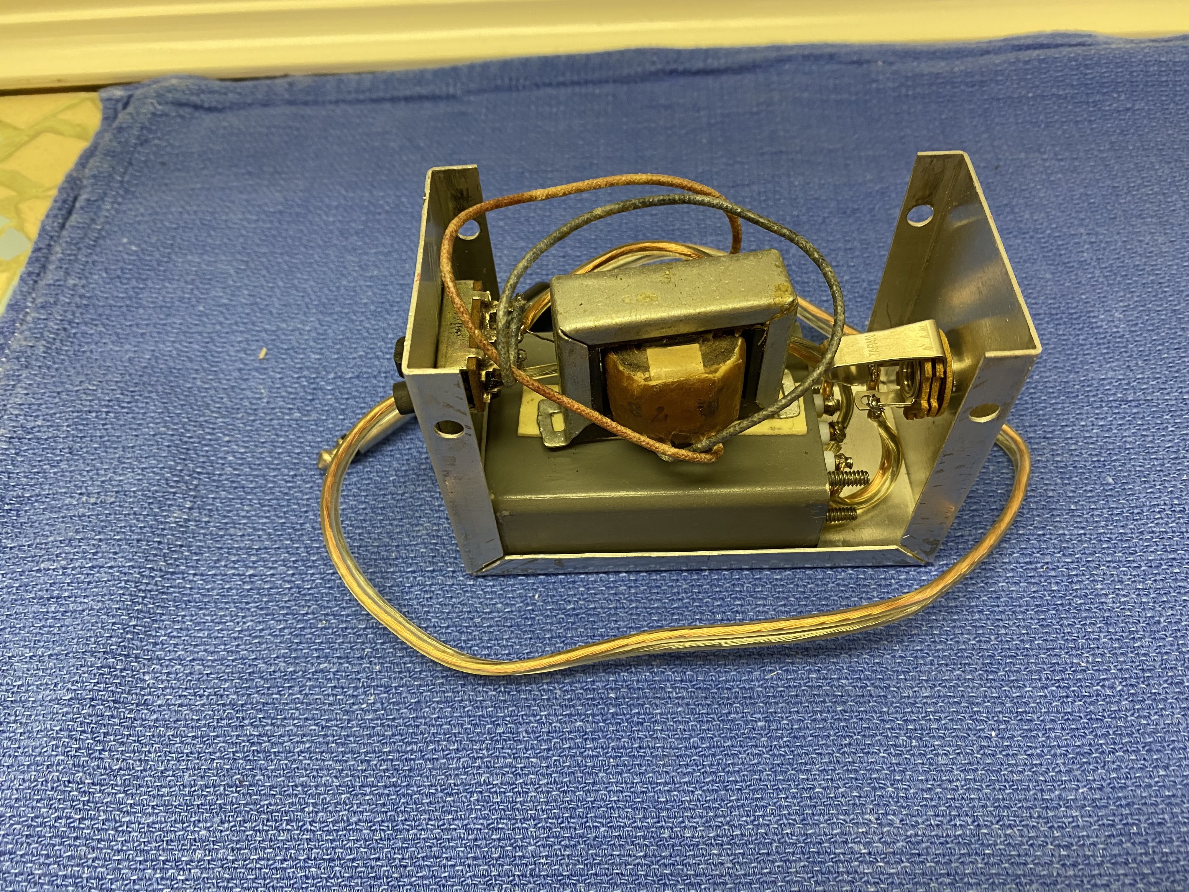 |
| Homebuilt CW filter with impedance switch |
Speaker
Antennas
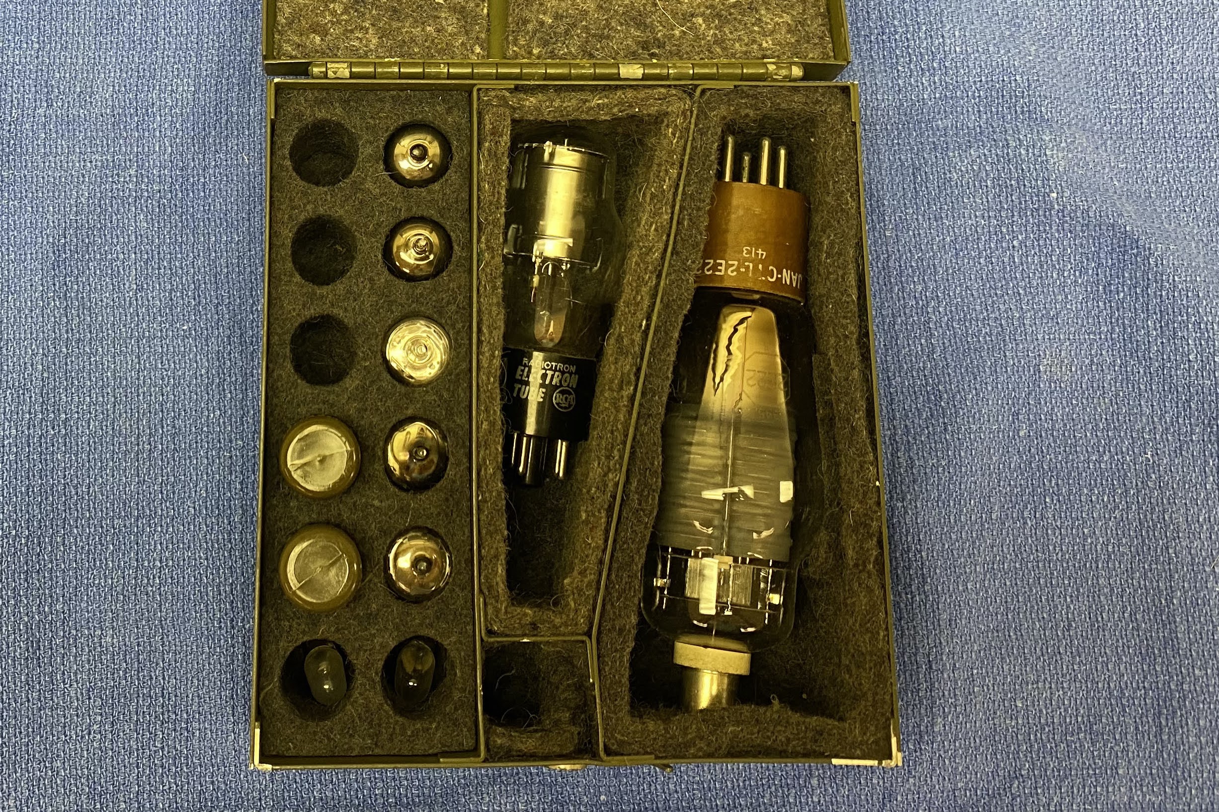
Spares
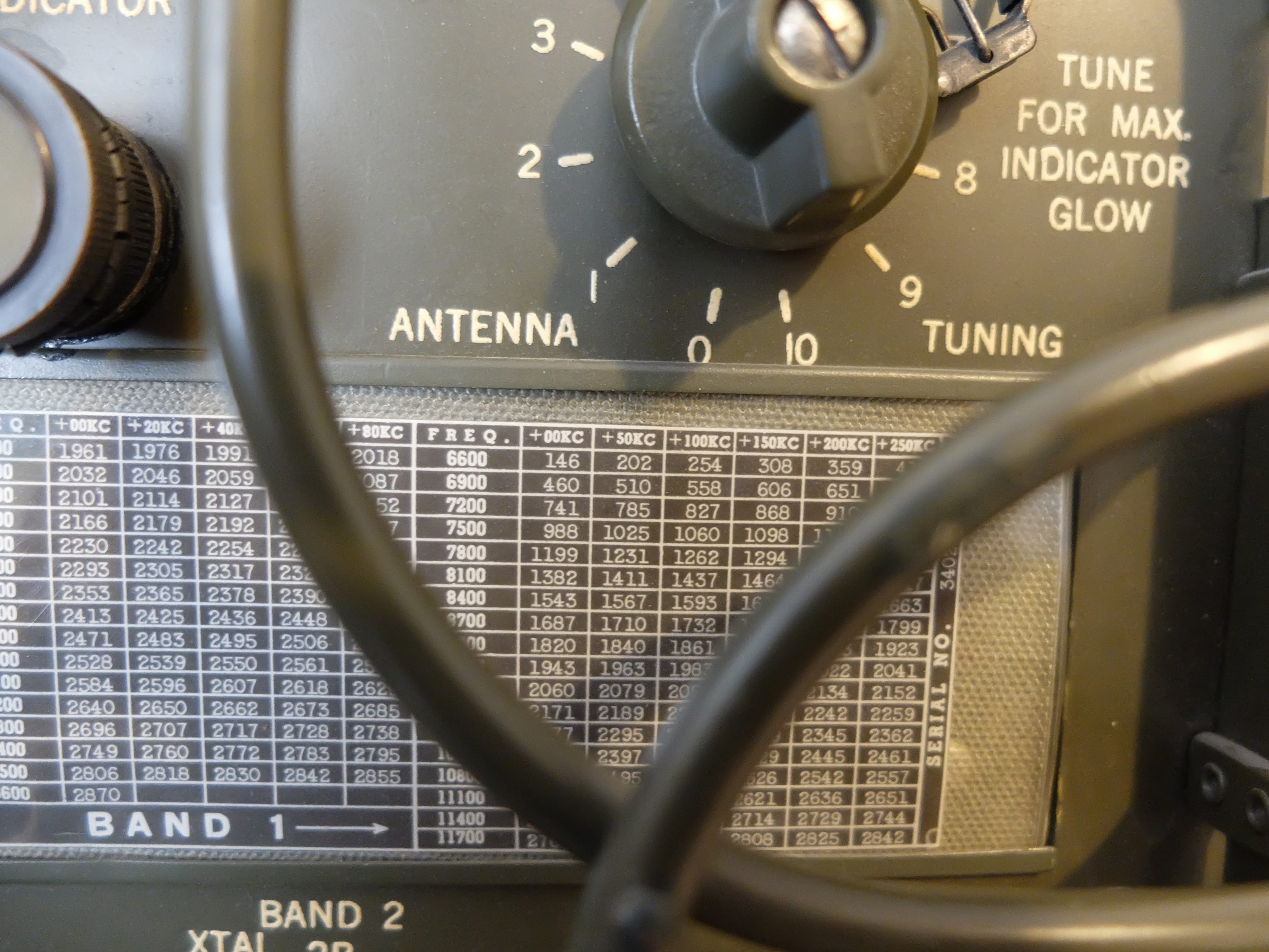
More to come
 |
| 50 kHz spacing when reading the frequency on the receiver Note the 7.2 is 7.200 MHz in the 40m band |
Images


