AN/GRC-9 - Long lived military comms
 |
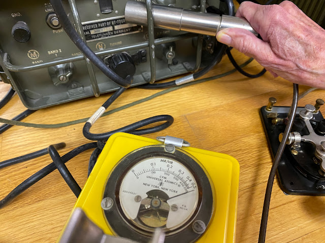
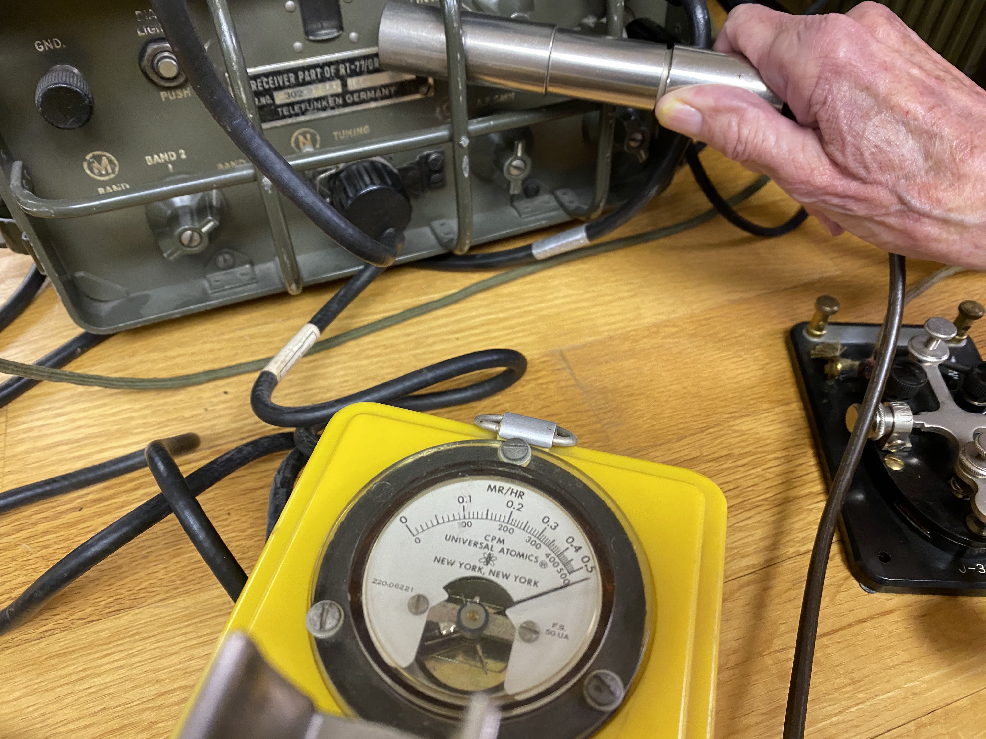
| My lovely (and radioactive) RT/77-GRC/9 |
I don't recall where I first read about the Angry Nine, but it captured my imagination. I read everything I could find about them and decided it would be great fun to operate such an antique on the ham bands. There is no logical reason to desire such a QRP radio. The low power output on CW is indeed, 5 watts and high power is a pileup busting 15 watts. The AM transmission are 1 watt and 7 watts respectively. That's almost QRPp for AM mode.
I'd had some experience restoring old tube equipment; my Heathkit HW-101, Knightkits VFO and Hallicrafters keyer, and I figured I'd take the next plunge and learn to use a receiver-transmitter combination and see how mobile high-voltage power worked from Vibrators and Dynamotors.
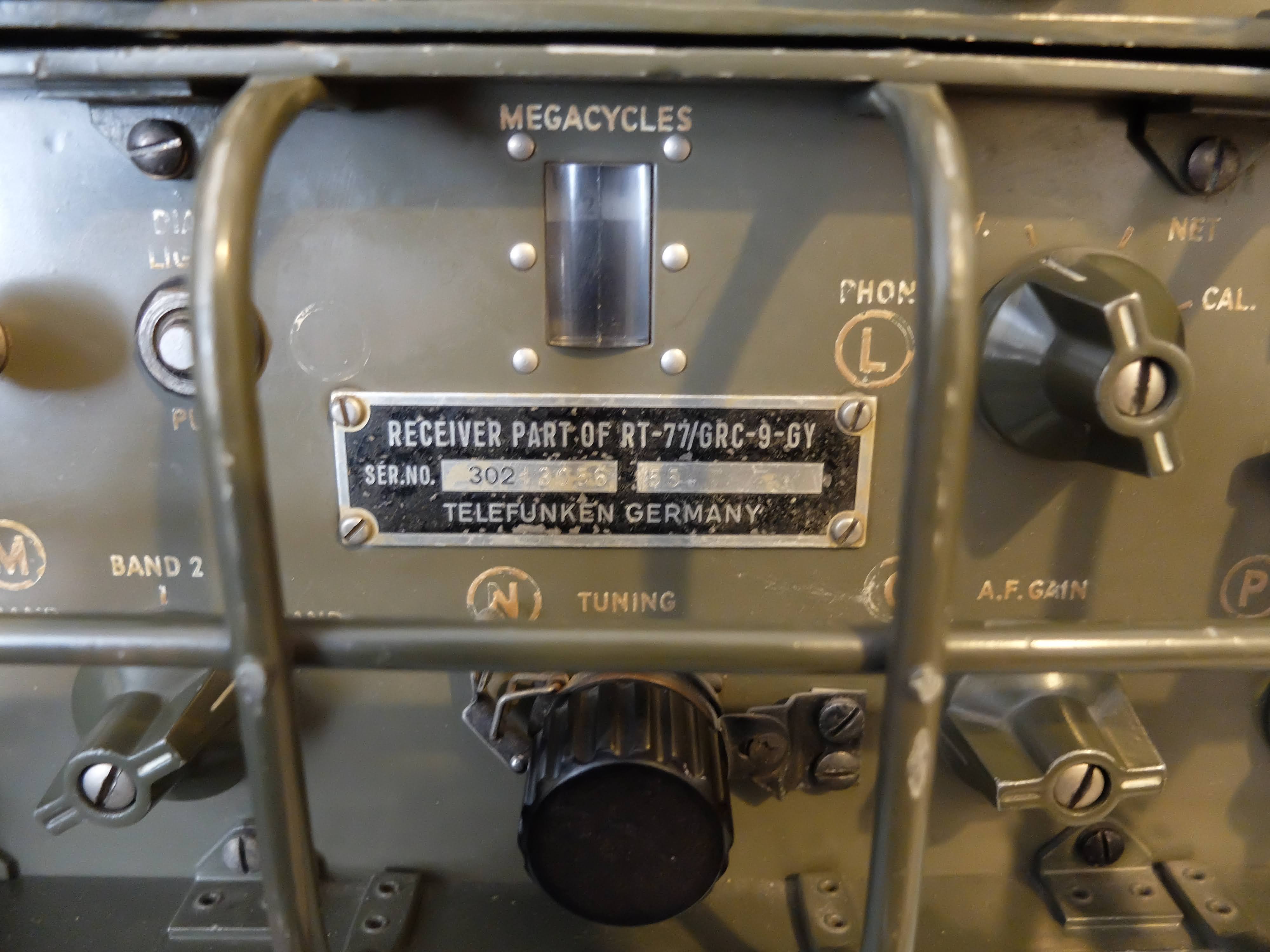
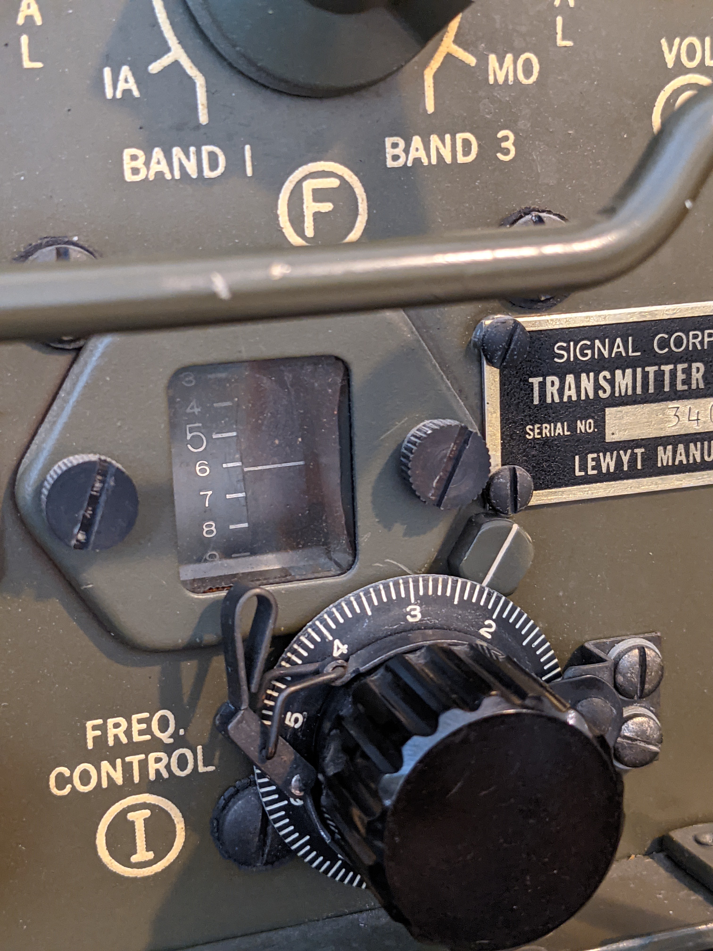
These radios seemed to have been more plentiful in the surplus market 10 - 20 years ago. Now you'll occasionally see one come up on eBay or other sites, but often times they are in very rough shape or the they are foreign language versions. I bid on a few auctions over the past couple of years and the bidding always exceeded my threshold for what I thought it was worth. The one above was part of an auction from an individual who had actually trained on these units prior to deploying to Vietnam. Later in life he became interested in finding one and spent time in military surplus warehouses going through pallets of equipment to find one in good shape. This particular unit is made up of a Lewt manufactured transmitter and a Telefunken receiver. The original owner preferred the receiver characteristics of the Telefunken over the Lewt manufactured model, so he paired the two.
Many of these old units are radioactive, due to the radium paint used on the front panels to make the lettering glow in the dark. This particular unit is off the lower scale on the Geiger counter and must be handled with care. Basically, I have to be careful to not touch my face with my hands after operating the unit and wash my hands thoroughly. Radium emits Alpha particles, which are not especially strong but the resultant radioactive dust from the front panel shouldn't be breathed or ingested.
 |
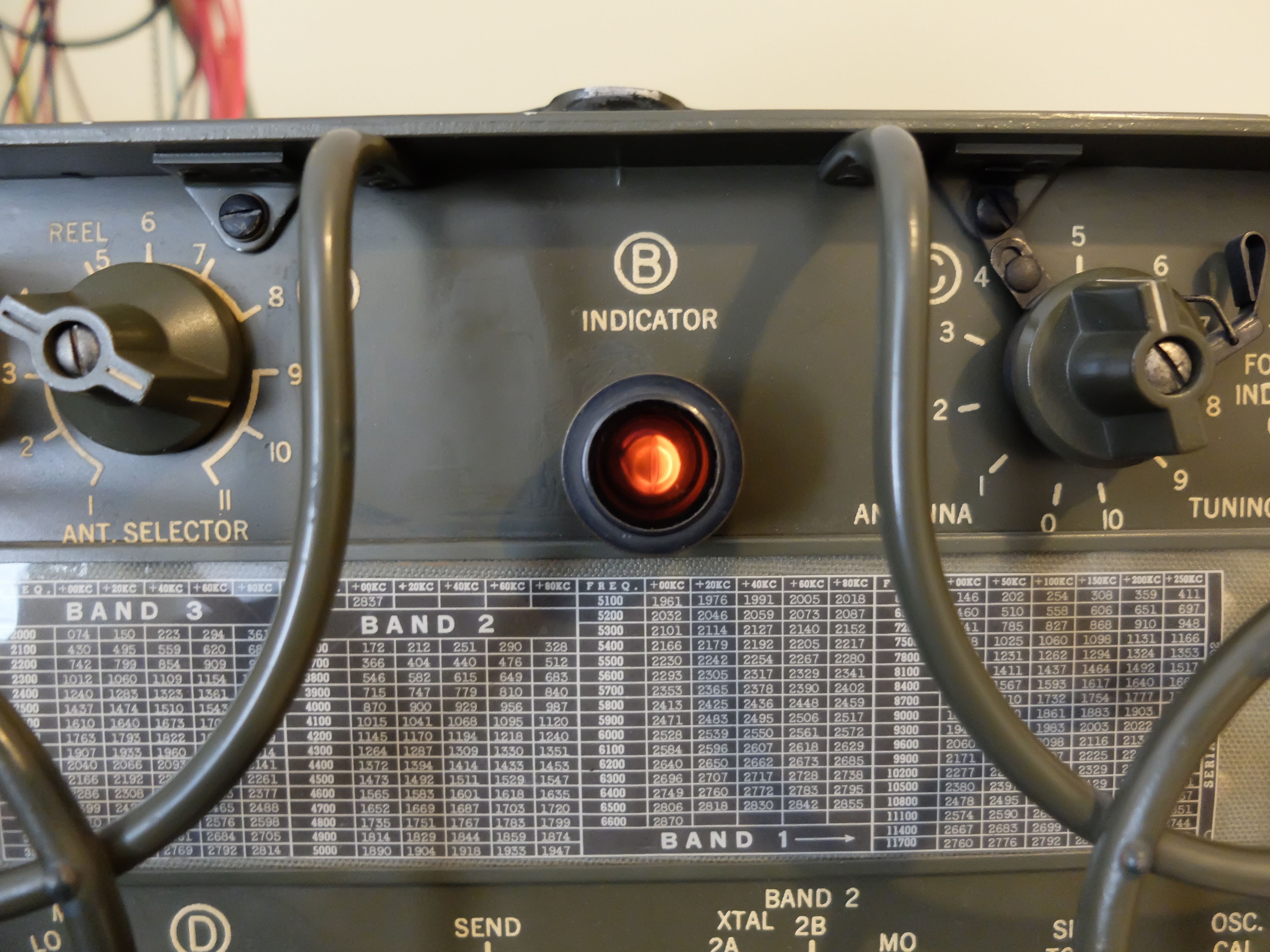
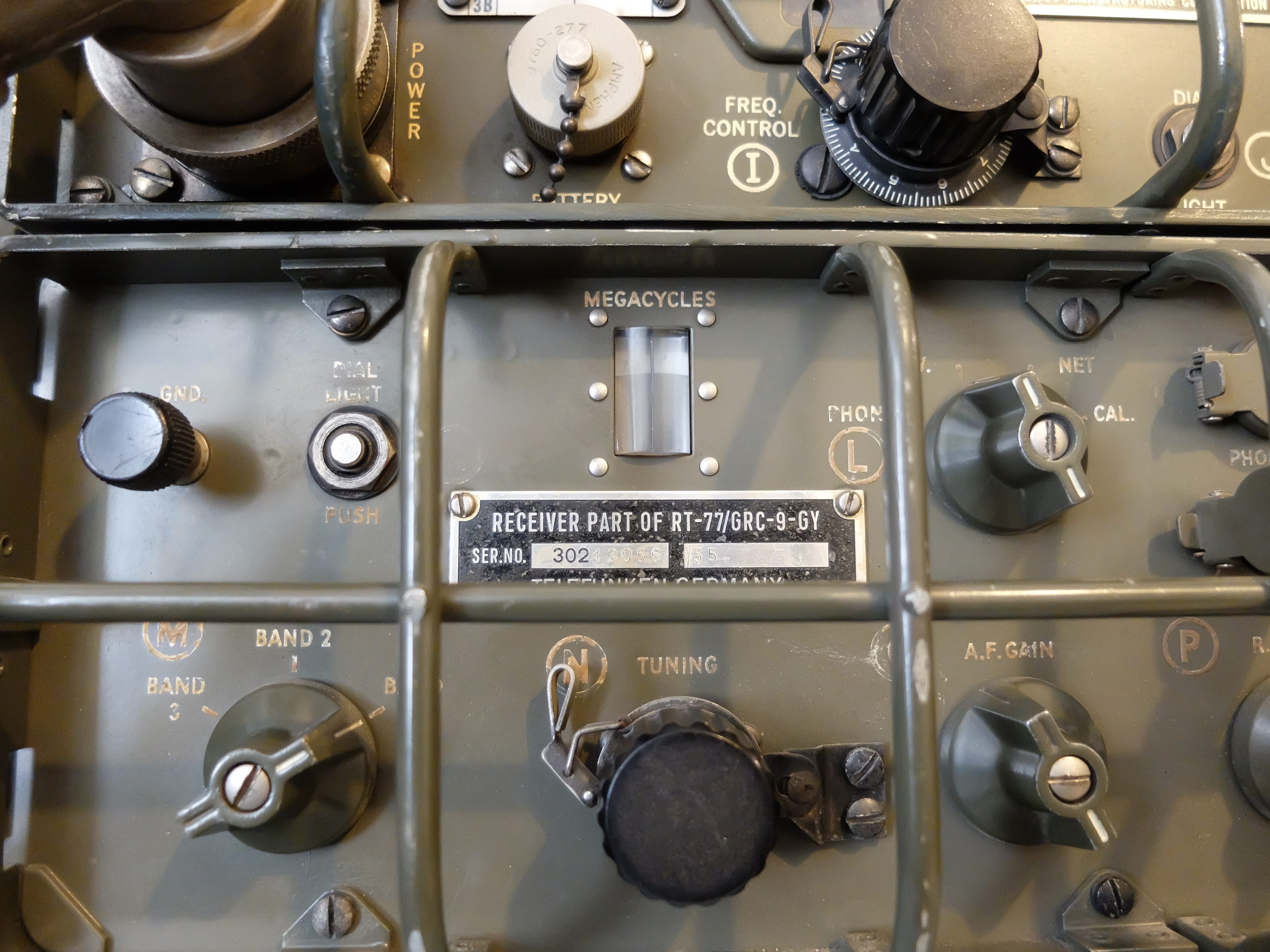
| Hot receiver, in more ways than one |
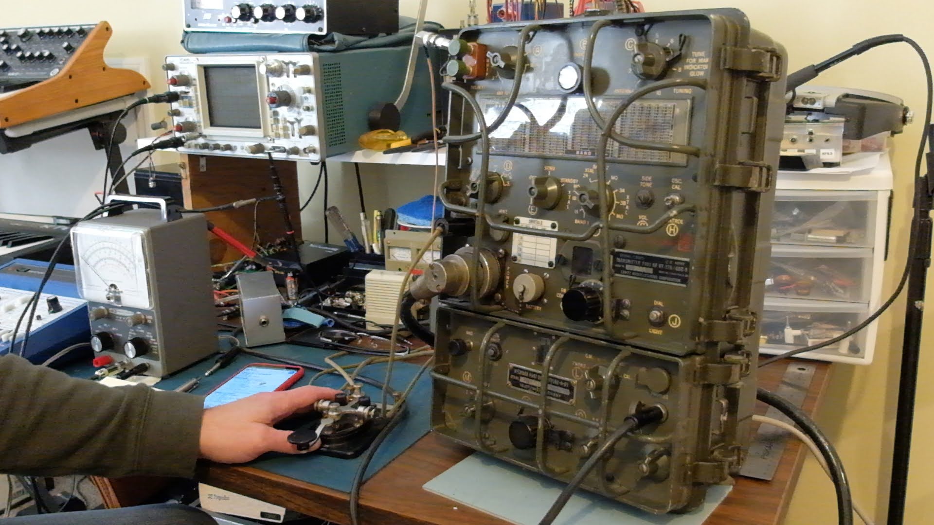
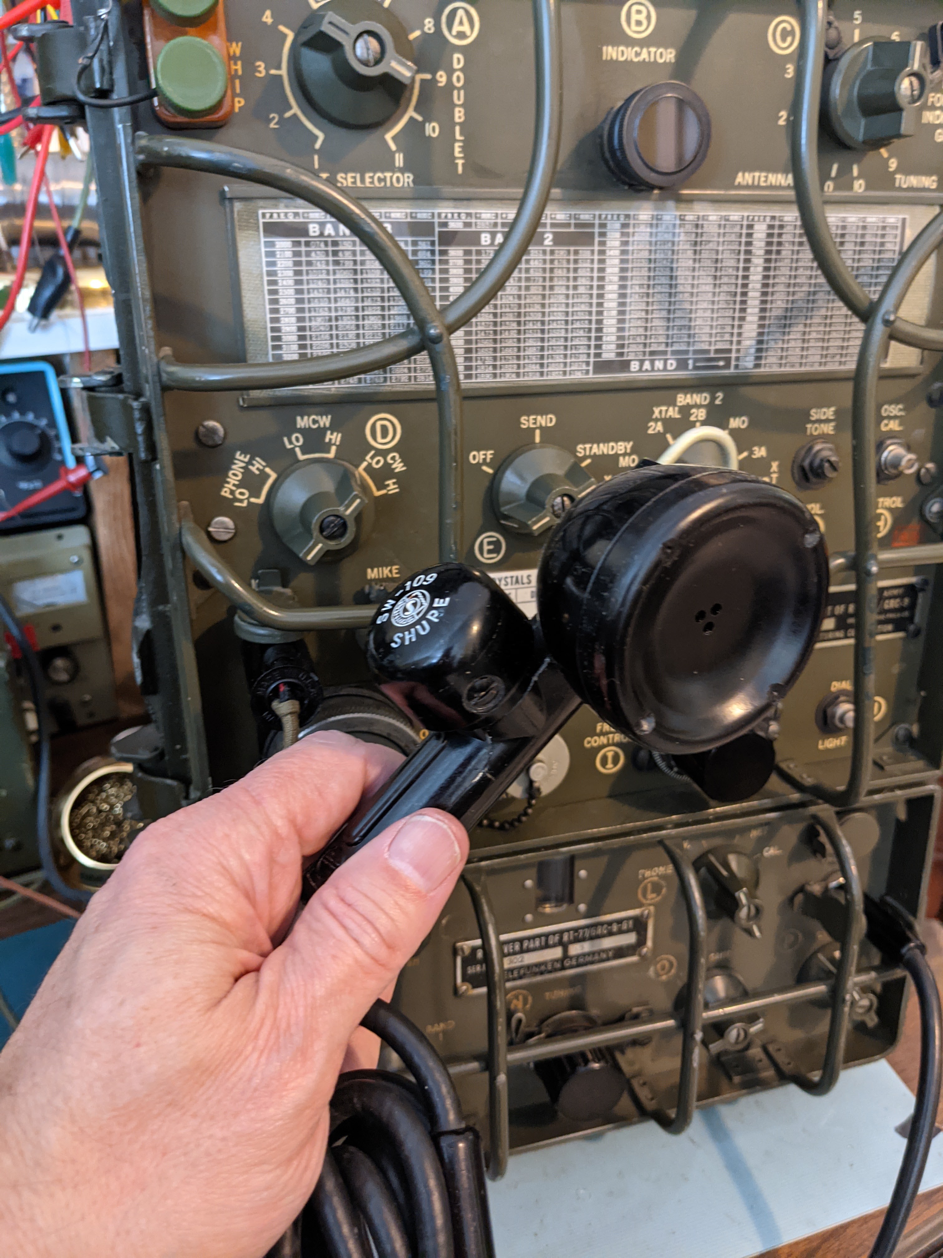
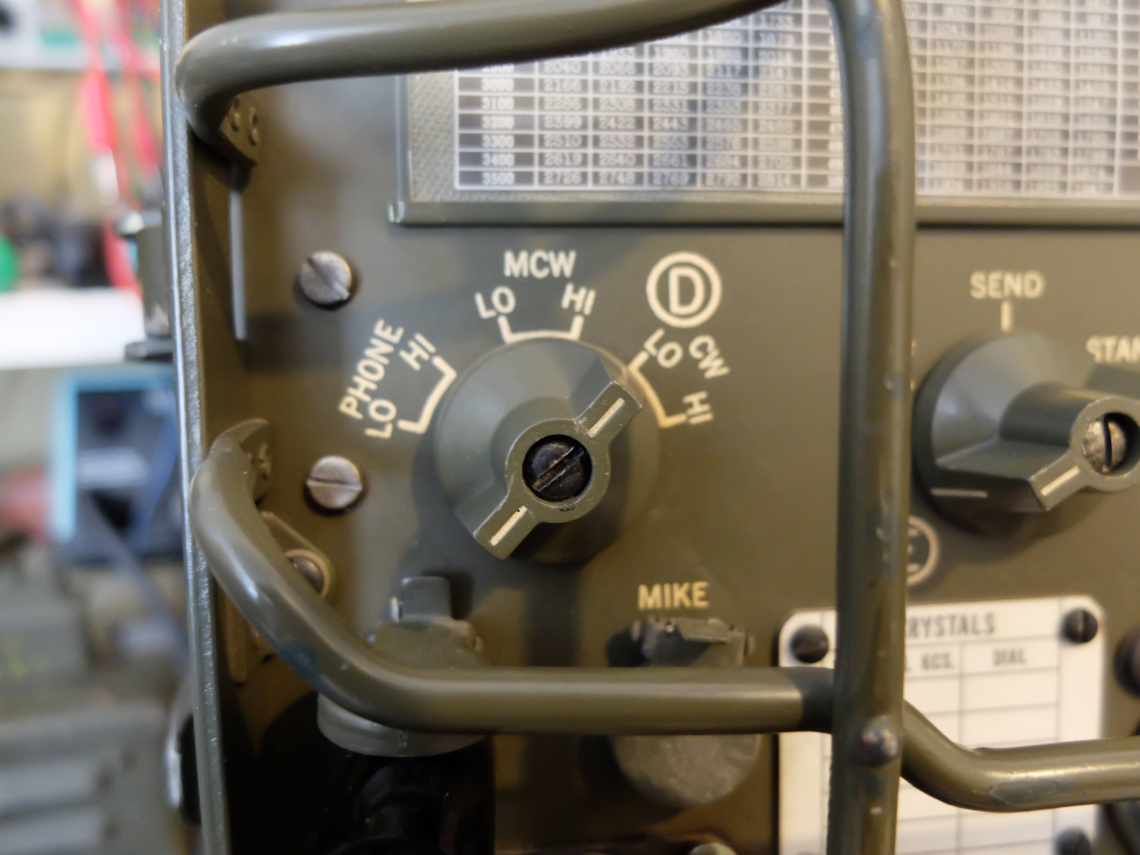
The AN/GRC-9 is a set of components primarily comprised of the RT-77/GRC-9 receiver-transmitter, capable of operating between 2-12 MHz in CW, MCW and AM modes. MCW is a modulated form of CW that can be received by radios that do not have a BFO (i.e. a normal AM receiver).
It is a mid to late 1940's design and was first documented field use in the Korean War, and was in active use through the Vietnam War and continued to be maintained in US military warehouses until 1974. It was in use by other nations long after, most notably the Dutch military.
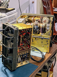 |
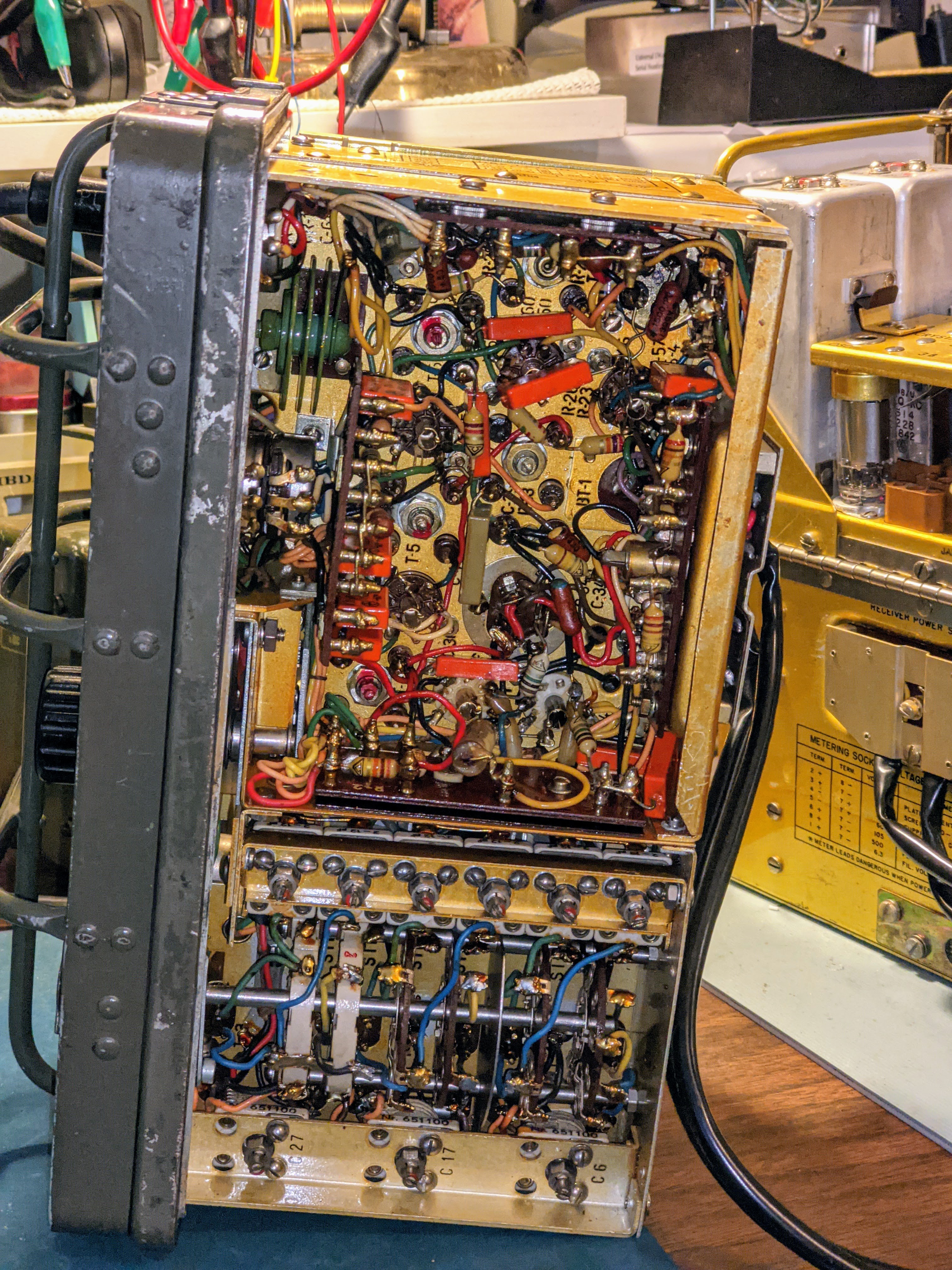
| Out of the case, tracing a low B+ power problem |
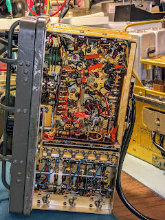 |
| Close up of the bottom of the receiver board |
 |
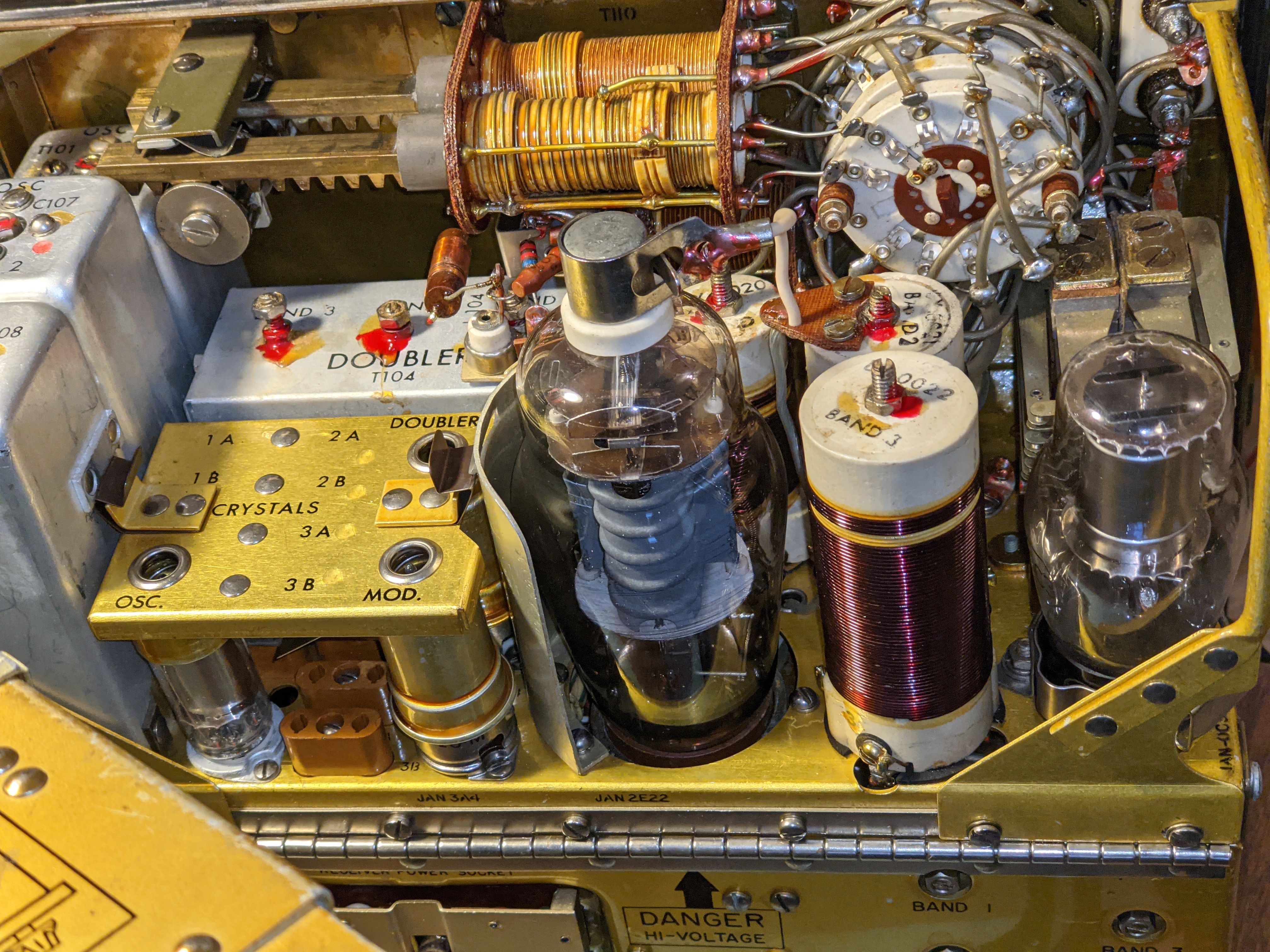
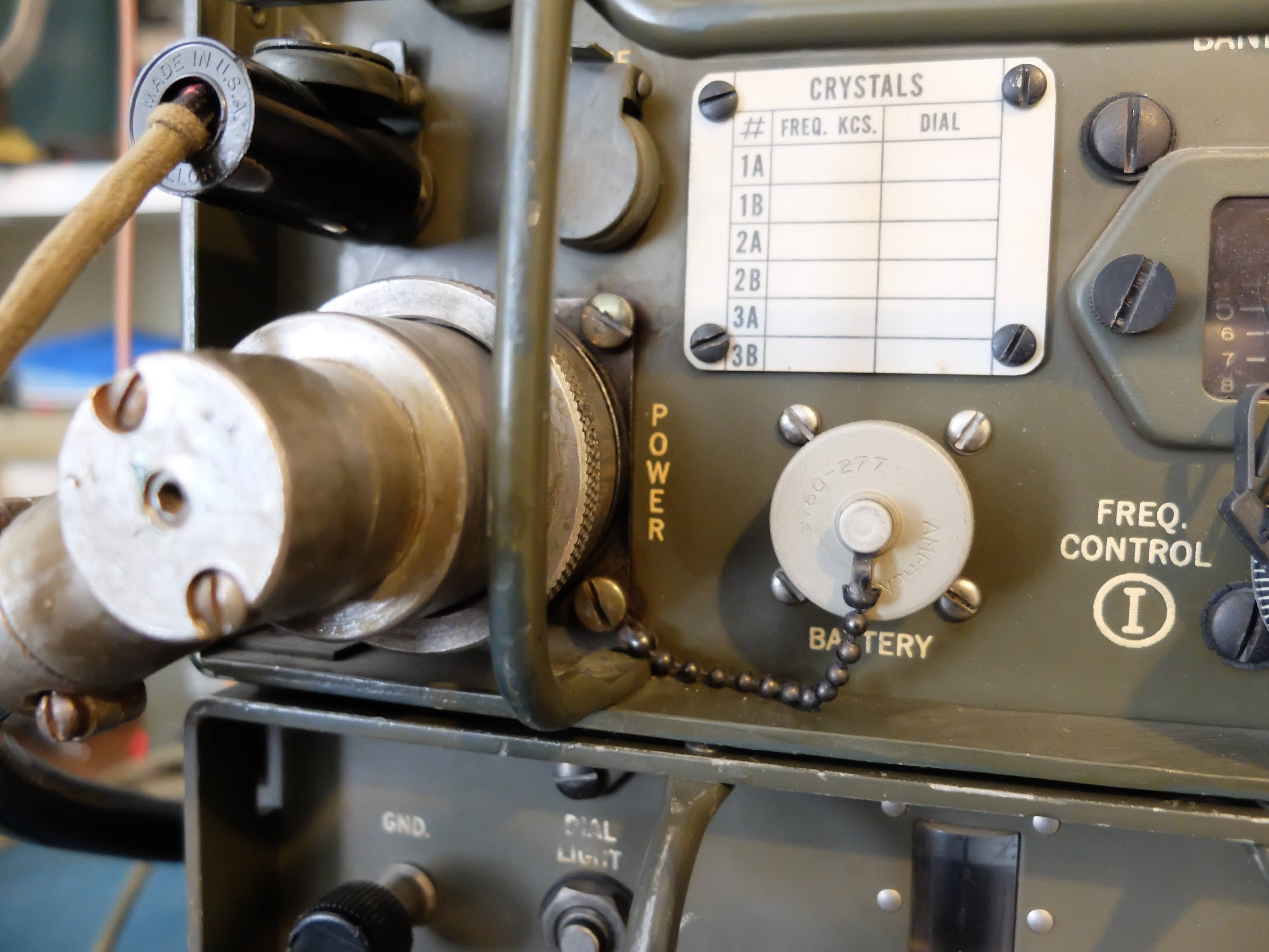
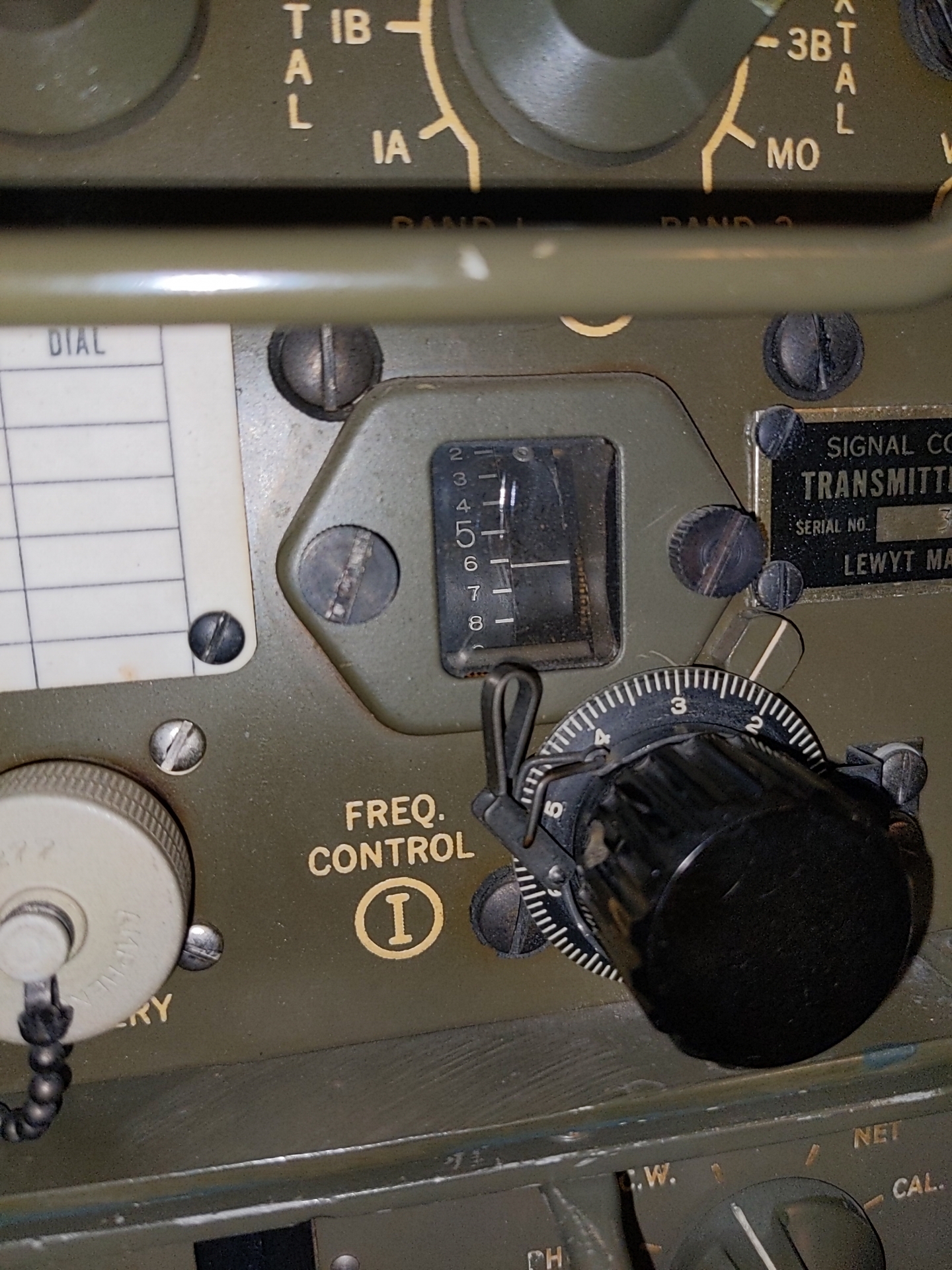
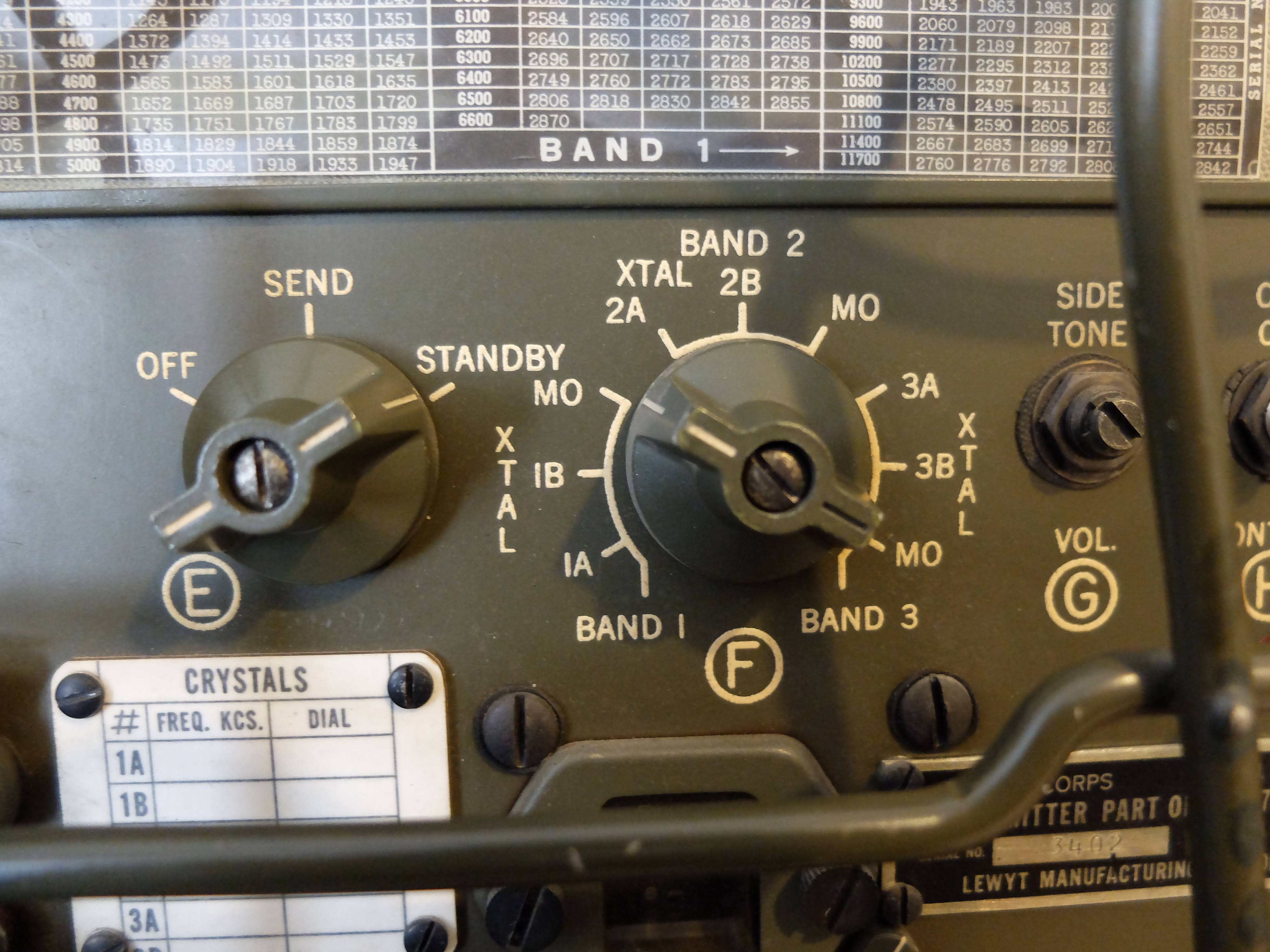
| Transmitter |
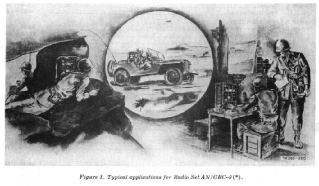
Power on the move
Designed to be used in the field, both vehicle mounted and carried by mobile infantry; there were a number of ways to supply power to the unit. There were a few different Vibrator/Dynamotor units, that could operate from common DC voltages of the time (6v, 12v, 24v) as well as a hand cranked, field portable generator.
Keep in mind that the state of the art at the time of its design used vacuum tube technology and in the case of the RT/77-GRC/9 it required the following voltages:
- Transmitter Plates -- 475 - 580 v @ 100ma
- Transmitter Filaments -- 6.5 - 6.6 v@ 2 amps
- Receiver Plates -- 105 - 120 v @ 45ma
- Receiver Filaments -- 1.35 - 1.5 v @ 500ma
- Keying Relay -- 6.0 - 6.9 v @ 575ma
That's a tall order for mobile and portable power supplies but designers in the 1940's were quite clever in packing power supply units. I managed to obtain both the hand cranked GN-58 generator with the base chassis and seat for portable operations, and a DY-88 for fixed / mobile operations.
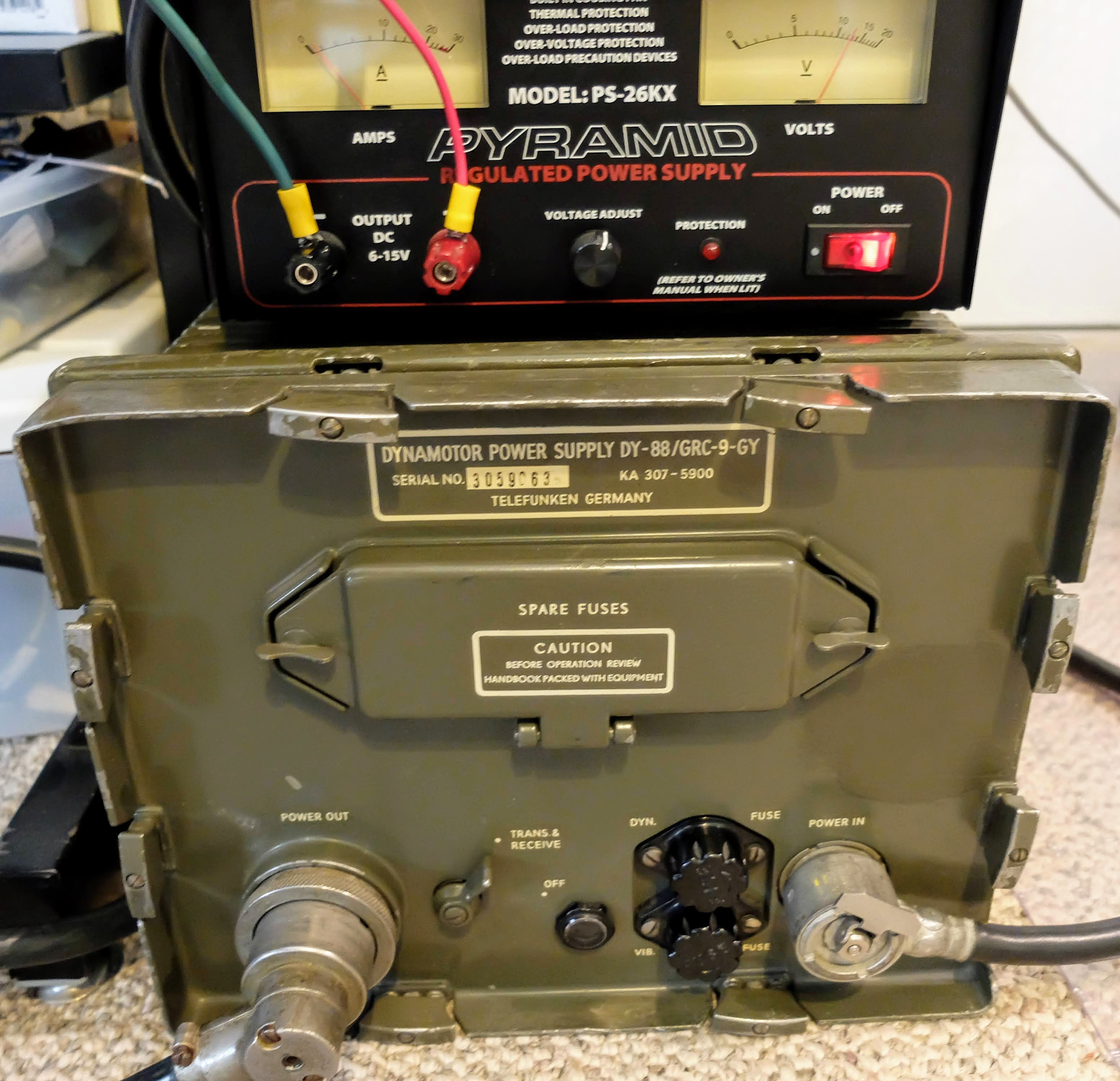
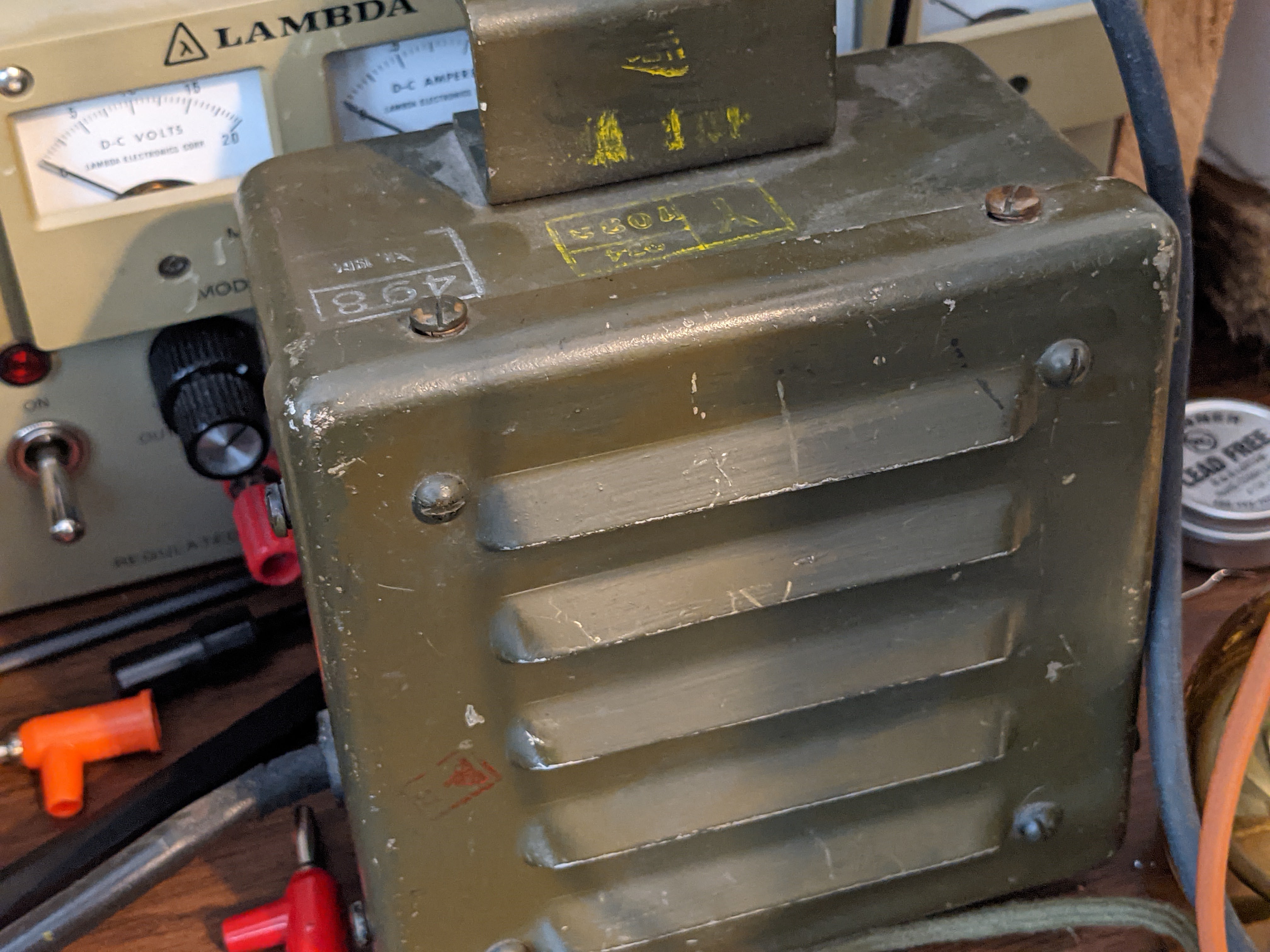
DY-88 mobile power supply
 |
| DY-88 set to 12v powered by Amateur 12v supply |
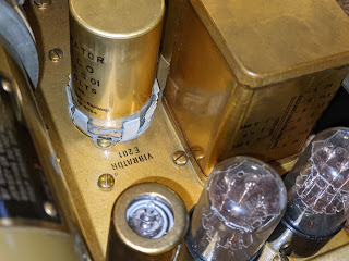 |
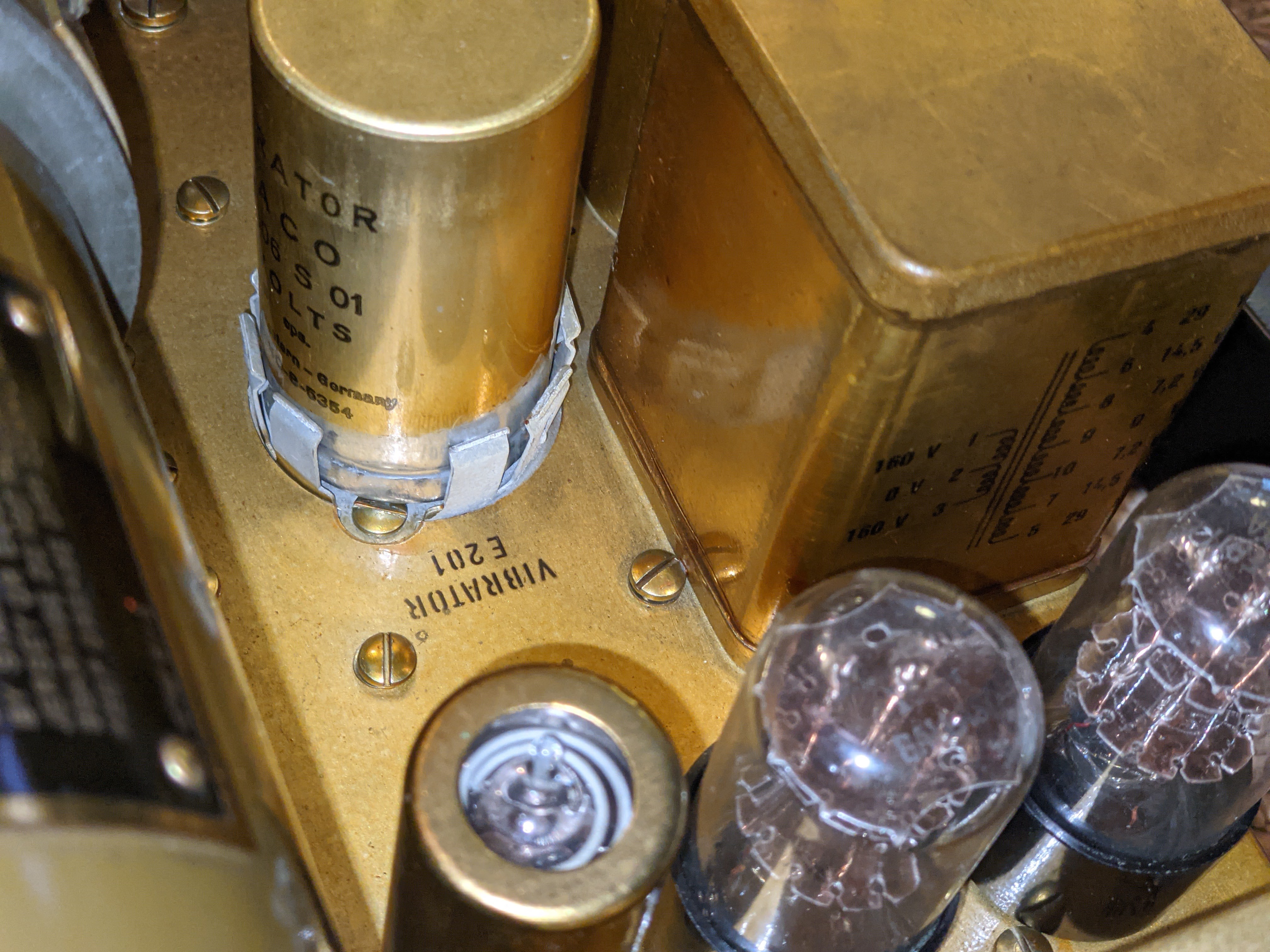
| Vibrator power supply for low B+ |
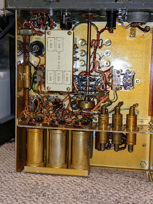 |
| Power filtering |
I supply the DY-88 from either an RV battery or an amateur 12v power supply. When in Standby the DY-88 draws less than 1 amp, but placing the radio in Send mode switches on the Dynamotor which draws 12 amps @12v, without key-down and up to 14 amps on high-output key-down. It will drain an RV battery pretty quickly at that rate if the radio is left in Send mode, and works an amateur power supply pretty hard as well. So don't expect to operate remote off a battery alone for too long if your having lengthy QSOs. An added benefit of the DY-88 is that when the enclosed Dynamotor is running you'll have a nice extra 85 dB of generator noise to accompany your listening pleasure.
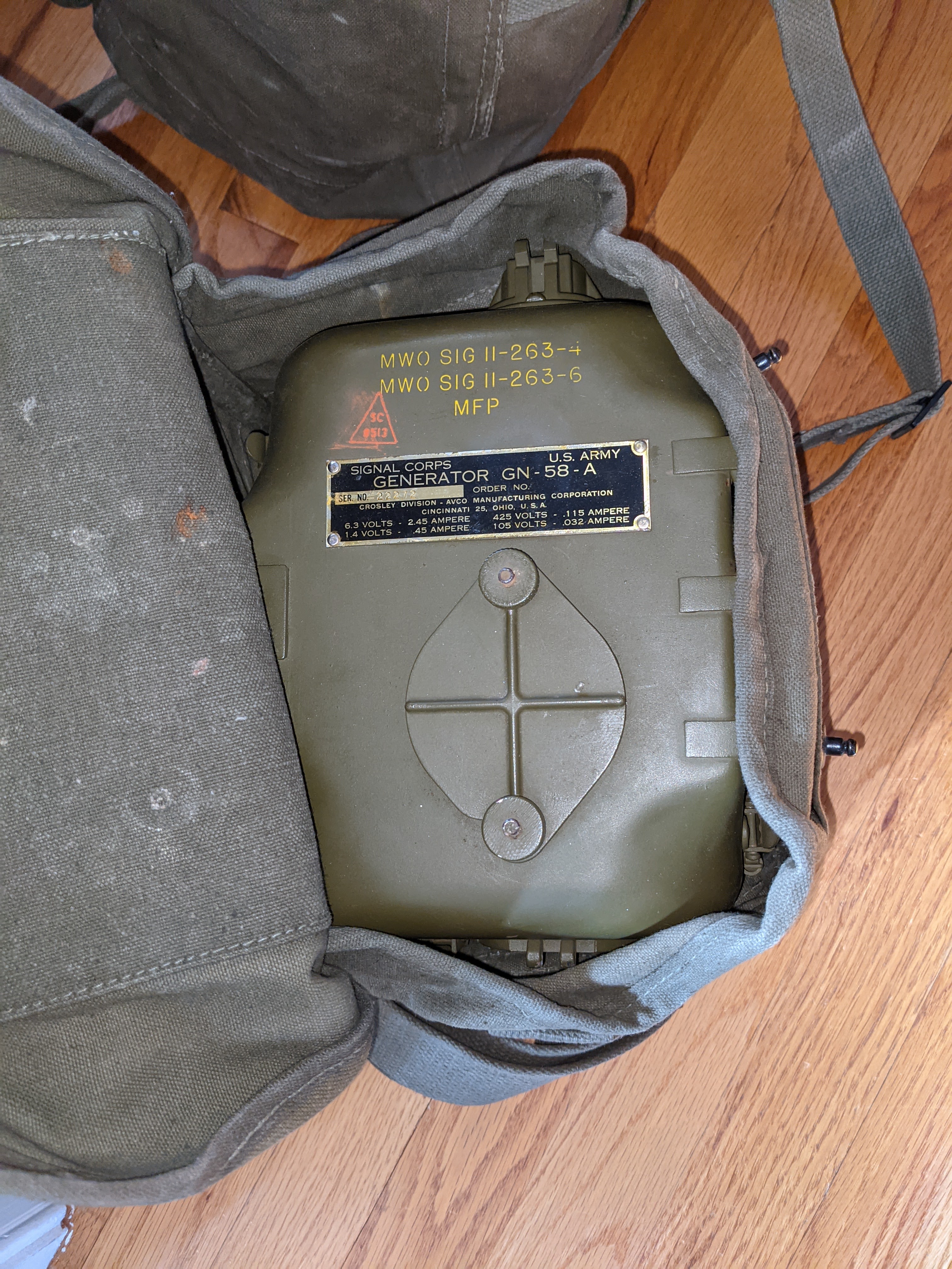
GN-58 portable field hand-cranked power supply
 |
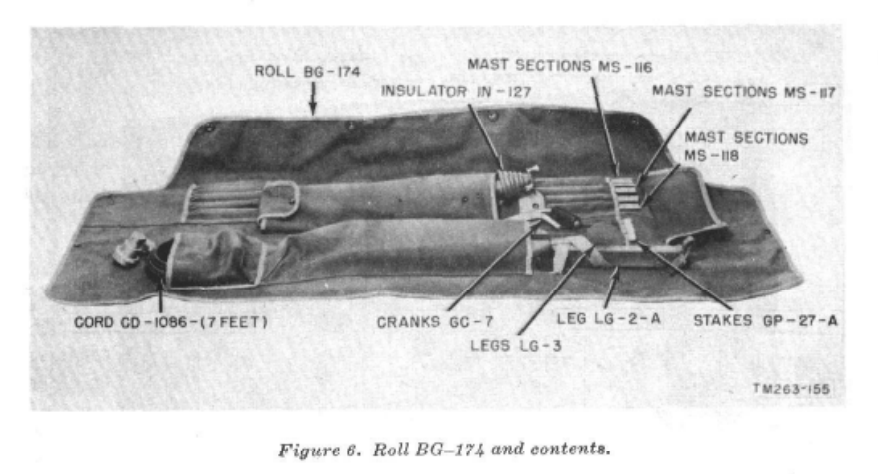
| Generator head in carry bag |
 |
| NOS Shiny |
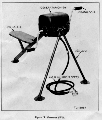 |
| Deployed |
The GN-58 is a tough workout since it has to be cranked by hand at 60 rpm continuously. Obviously, you need a partner unless you can figure out how to crank it with your feet while sending CW. You will also want that partner to help you carry the GN-58, and the accompanying accessory bag for the chassis and seat. IT'S HEAVY. I haven't weighed everything, but according to the manual that came with the set, the radio / generator / accessories including antennas comes out around 120 lbs.
If you have a BC-48 battery hooked up then your human power supply can pause cranking while your receiving. I have a BC-48 battery enclosure that has been gutted of the original, long-dead material and replaced with 10x 9v batteries in series for the low B+ and two D-Cell batteries in parallel for the receiver filament supply.
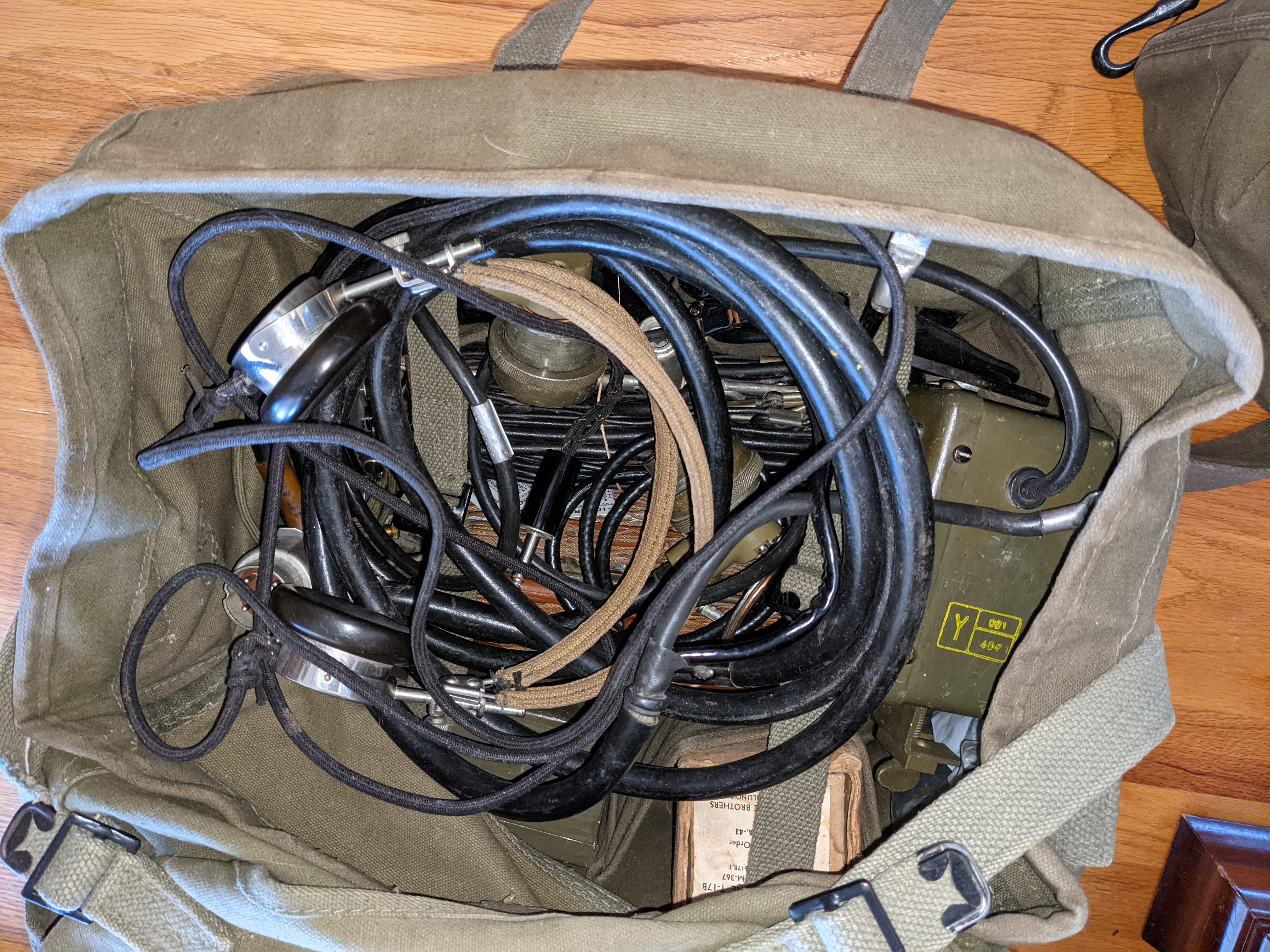
Accessories
 |
| Bag of goodies |
The radio itself has a carry bag, as well as a bag for the GN-58 legs and seat, the vertical antenna, and miscellaneous.
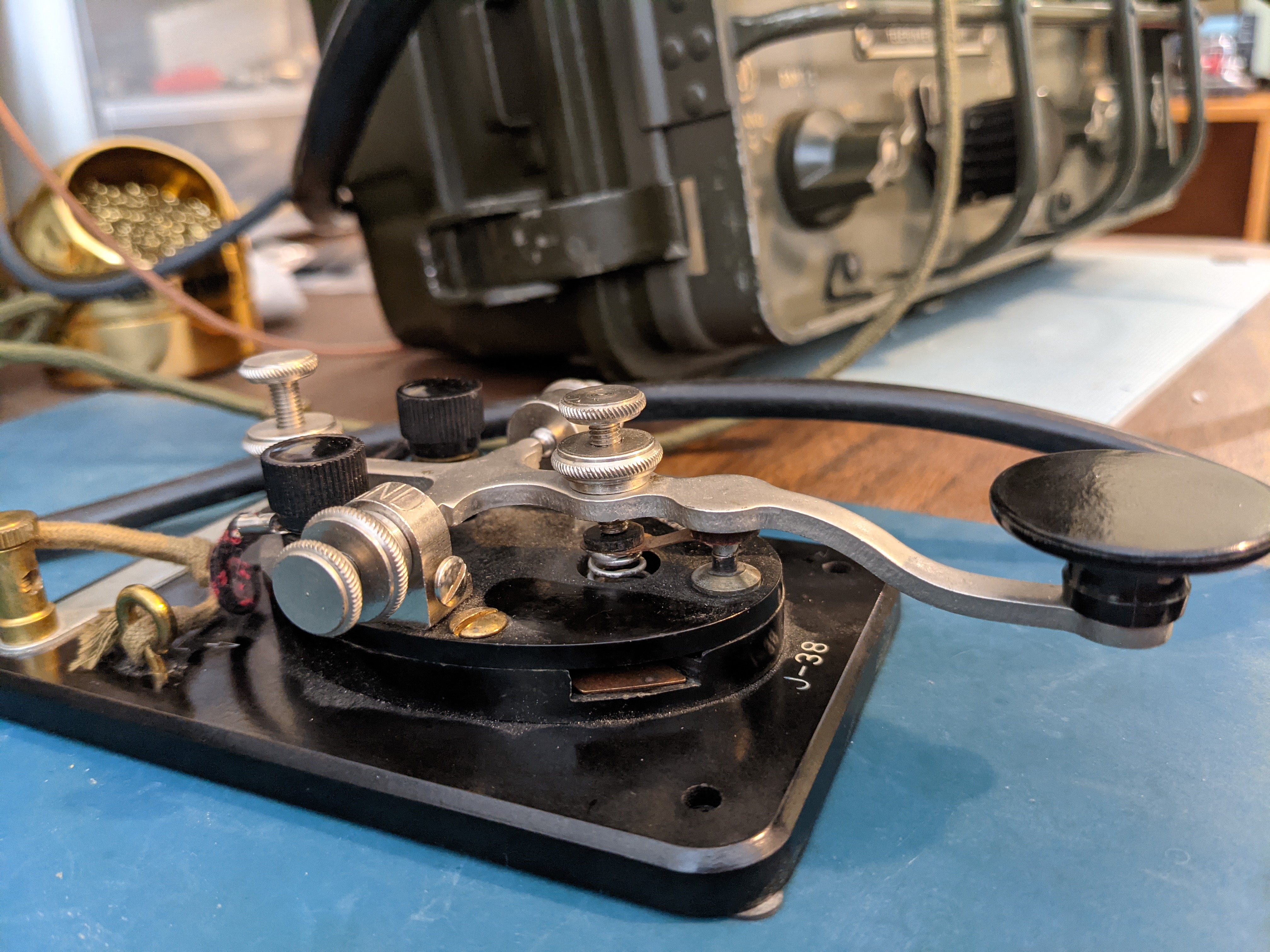
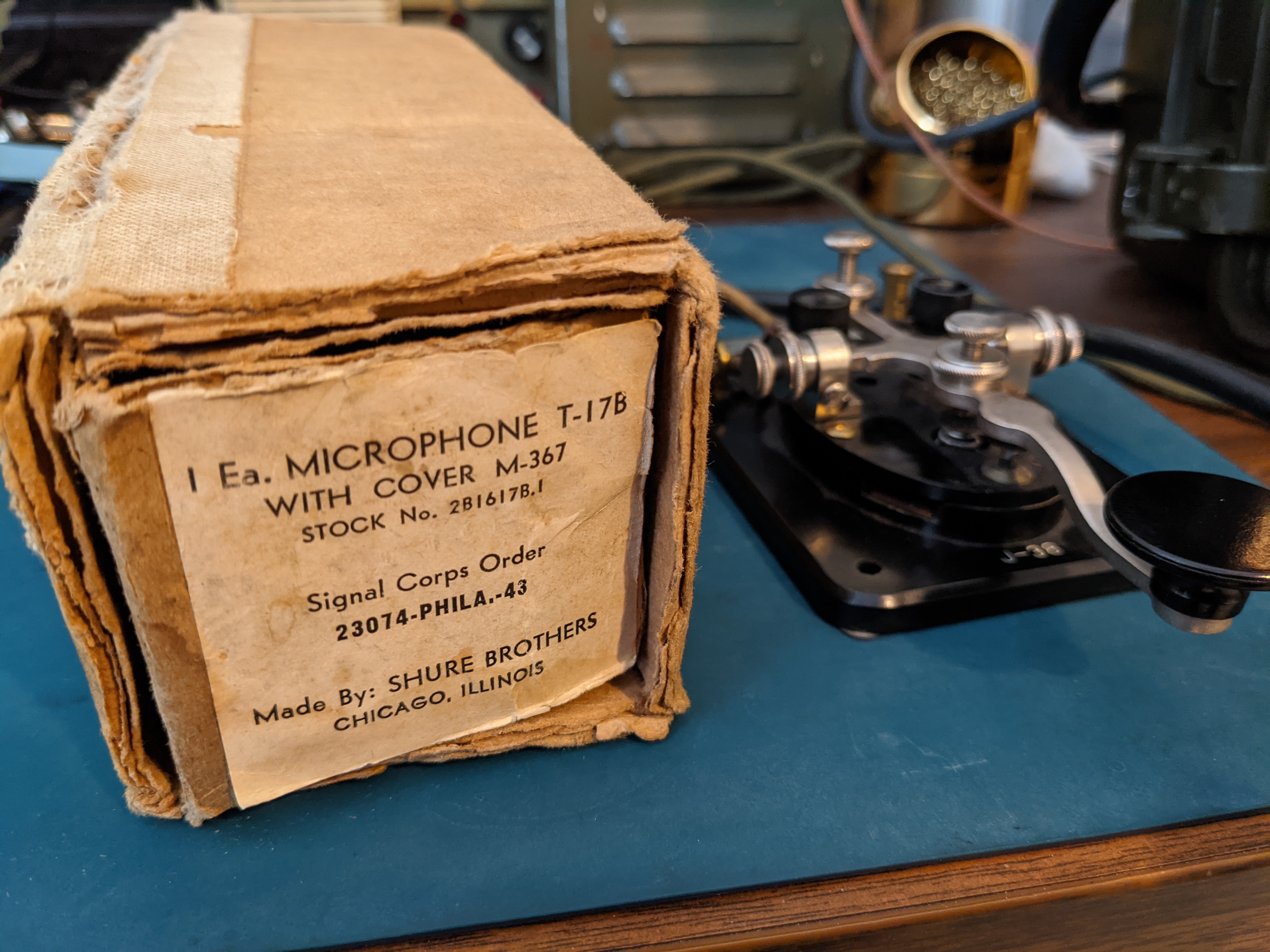
There's another bag (shown above) for carrying power supply cables, keys, hand mic, long wire and doublet antennas, external speaker, torture device headphones, torture device in-ear phones, as well as a box of spare tubes for the radio.
If you're traveling in a squad sized group, then many hands make light work, otherwise you're going to be making a lot of trips hauling your QRP rig up the hill.
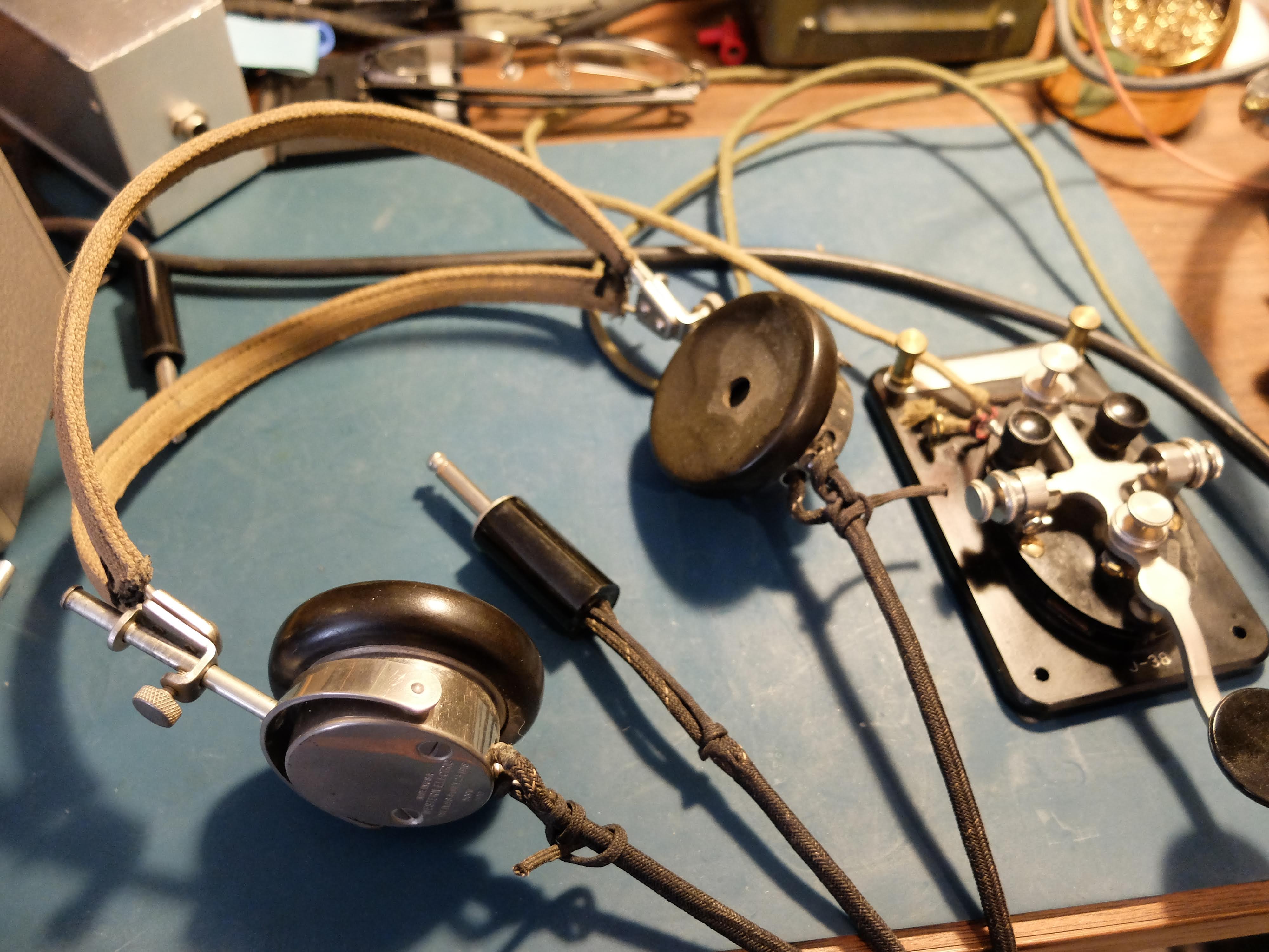
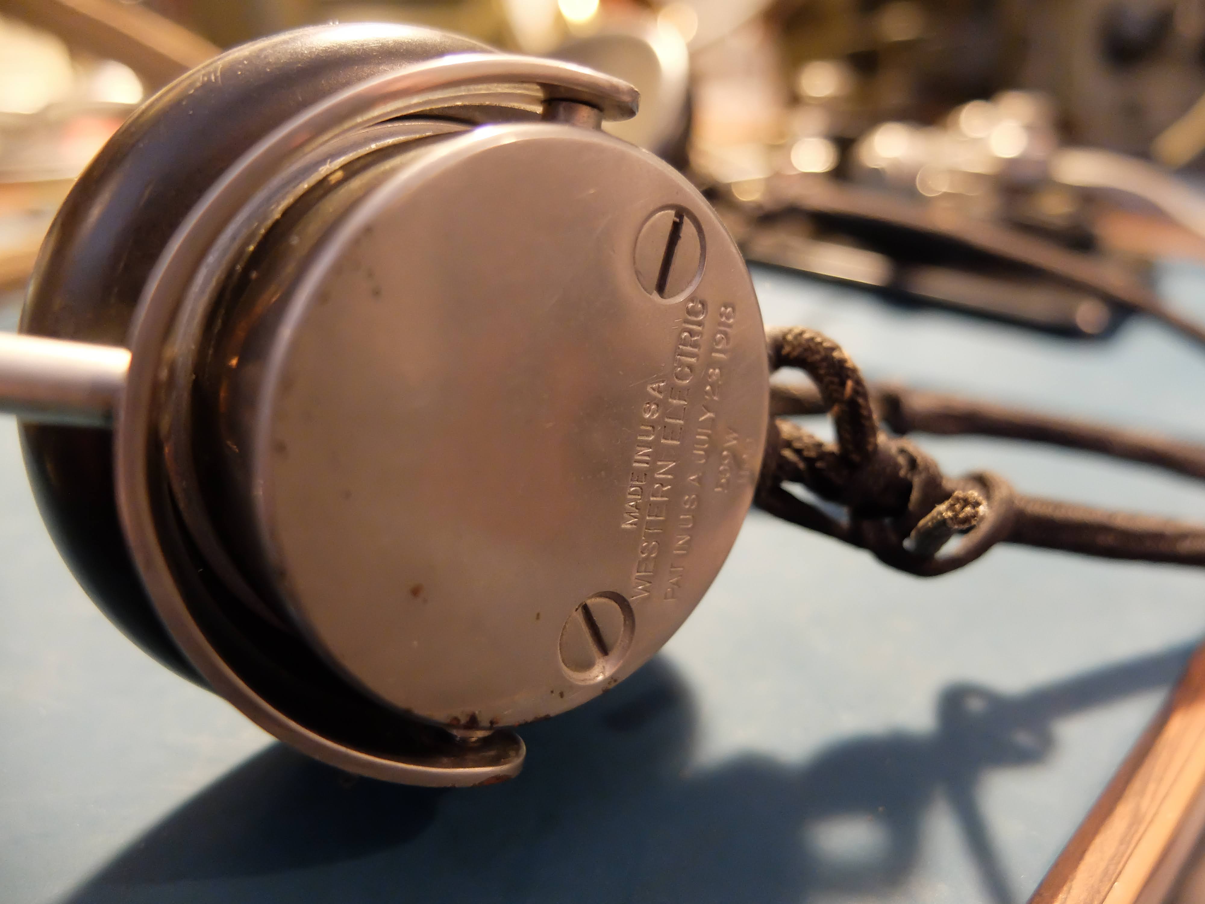
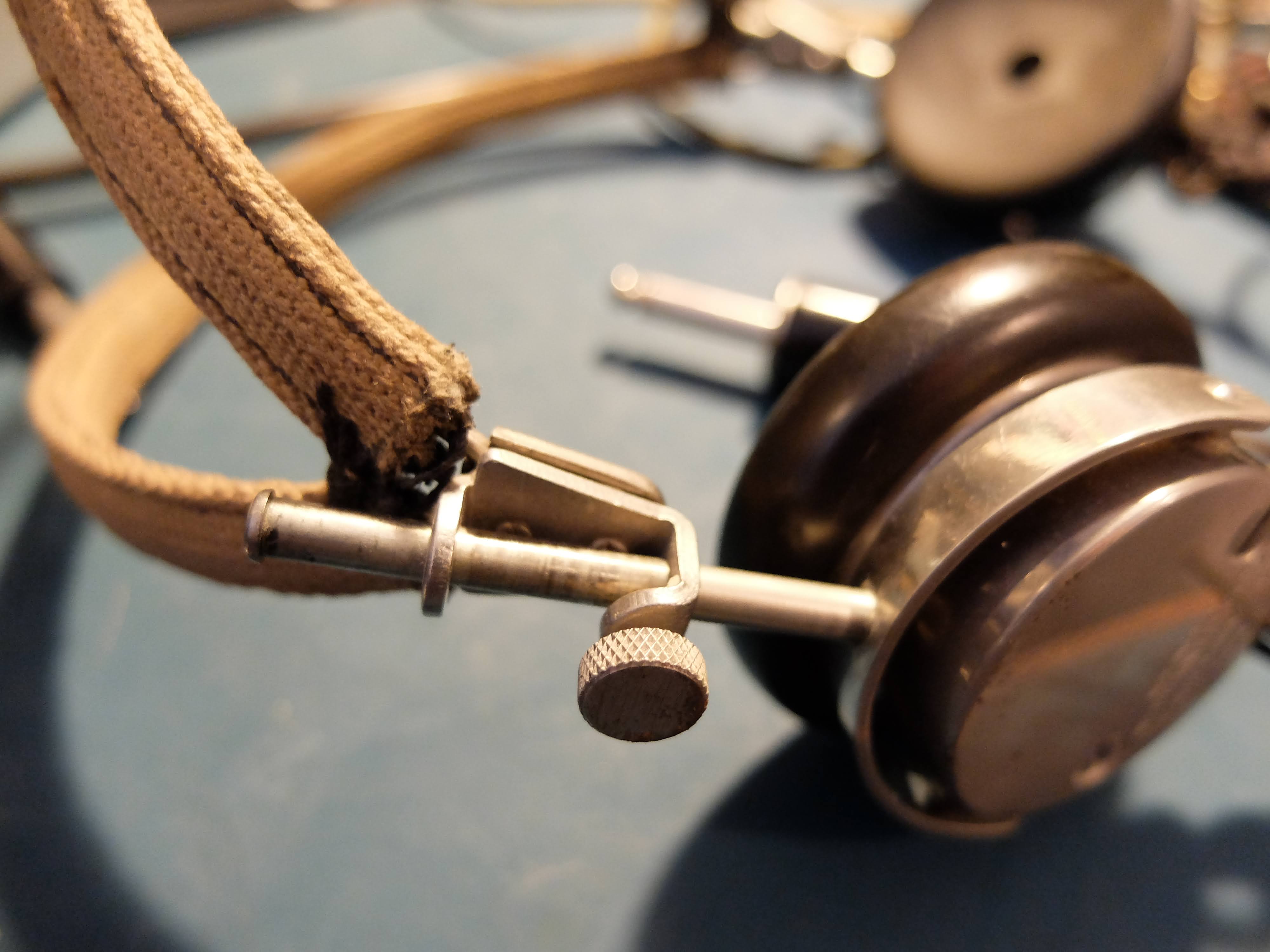
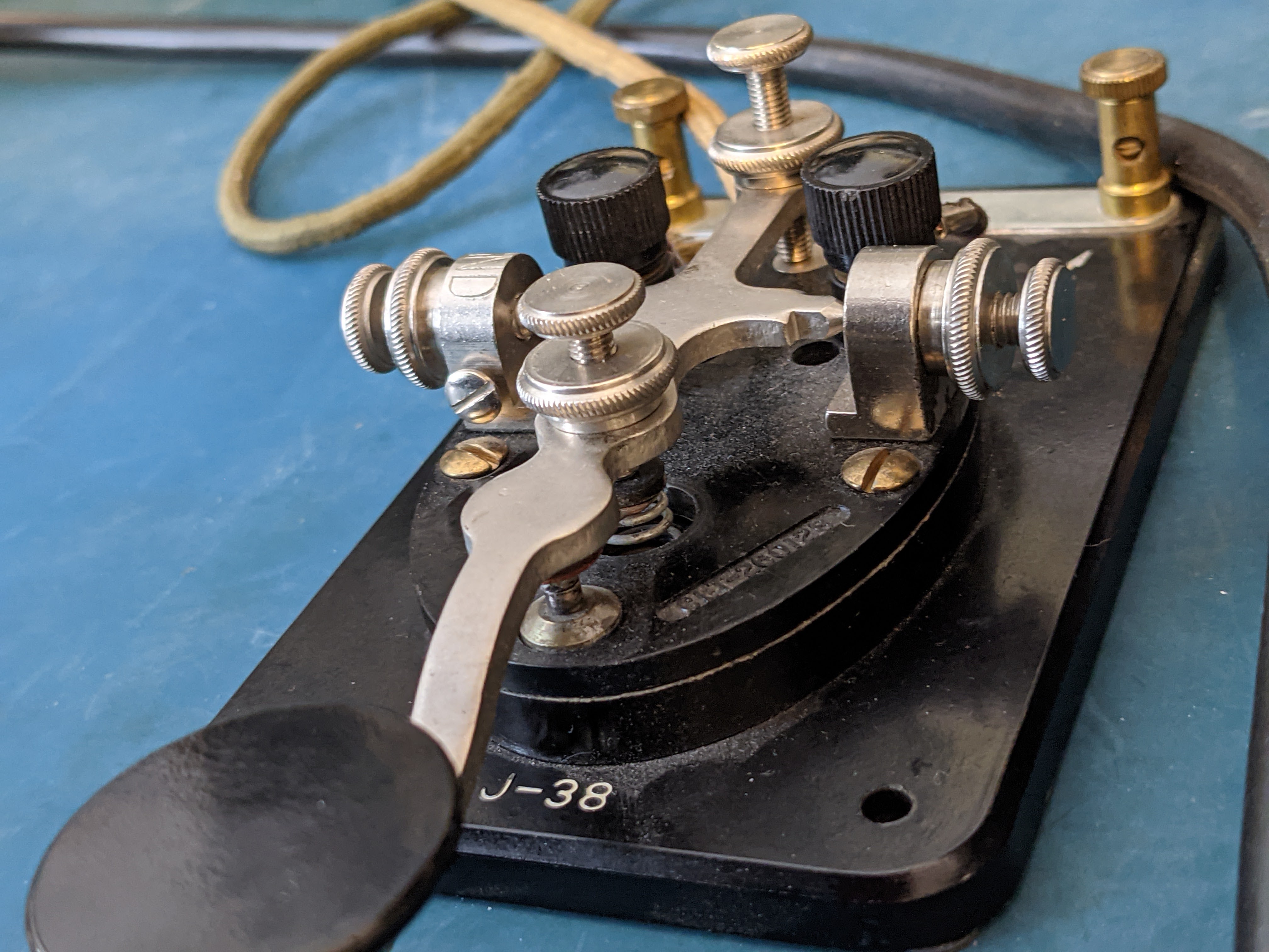
Headphones
These Western Electric headphones clamp tightly over your ears sealing out QRM and squeezing your head like a vice. After 10 minutes I was confessing to sins I'd never committed.
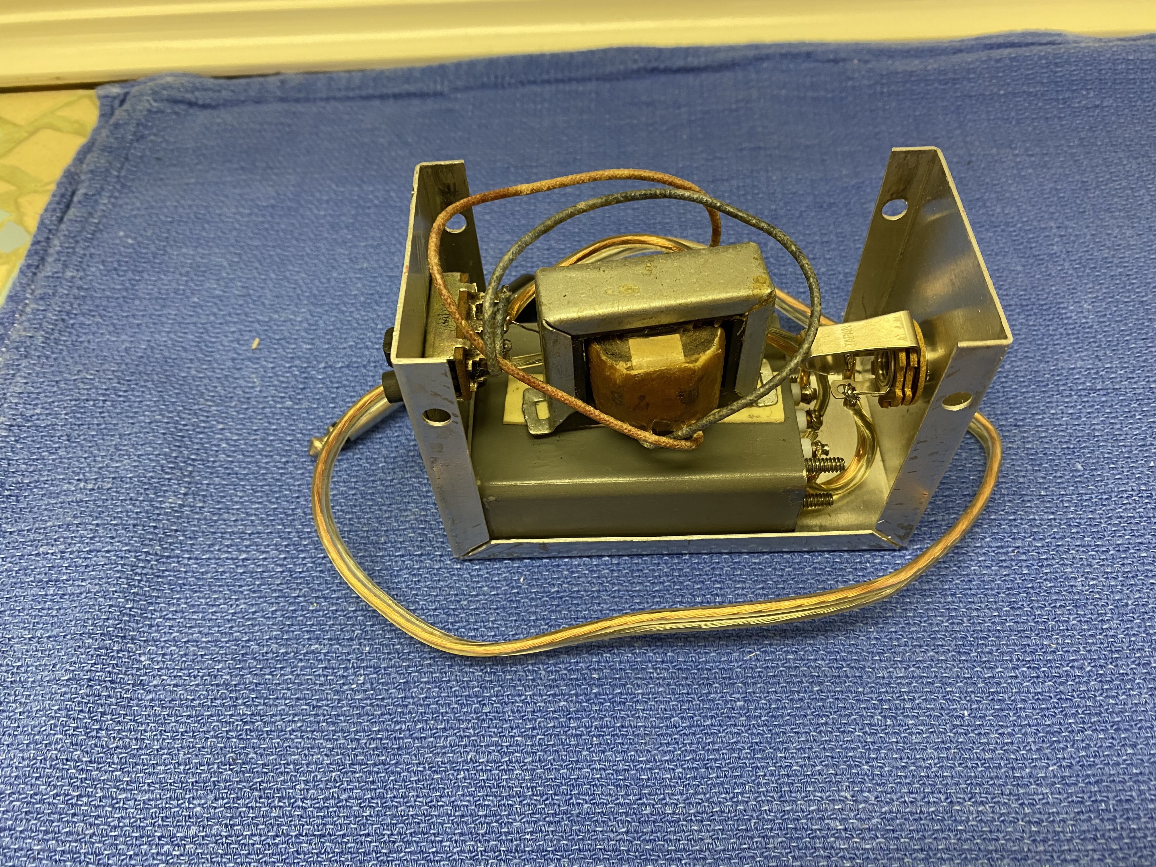
In order to use the headphones the RT/77 receiver must be removed from the case and an impedance switch on the back, changed from 4000 to 250 using a screwdriver. The ham I bought my set from had constructed a CW audio filter along with an impedance switch on an outboard box, that allowed the use of the headphones without switching the impedance on the receiver unit.
 |
| Homebuilt CW filter with impedance switch |
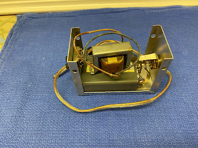
Speaker
The external speaker is a rugged, high impedance device (4k Ohms), that after all these years can still output audio at high volumes without distortion. It has a built in thumbscrew clamp that allows it to be attached to vertical or horizontal objects.
Alternately, the thumbscrew can be used in combination with the vice-like headphones to extract information from a prisoner.
Antennas
The AN/GRC-9 comes with 3 antenna systems; a multiple section, whip vertical for quick field setup and mobile use, a long wire that can be quickly deployed in a fixed station as a sloper, and a doublet for best reception, transmission in a fixed location.
For testing purposes I have my radio hooked up to my 80m Windom, which it tunes very nicely on 80m, 60m, 40m and 10m bands.
When the weather warms a bit I will be taking the radio out for some portable use and I'll try it out with the antennas that are part of the AN/GRC-9 set.
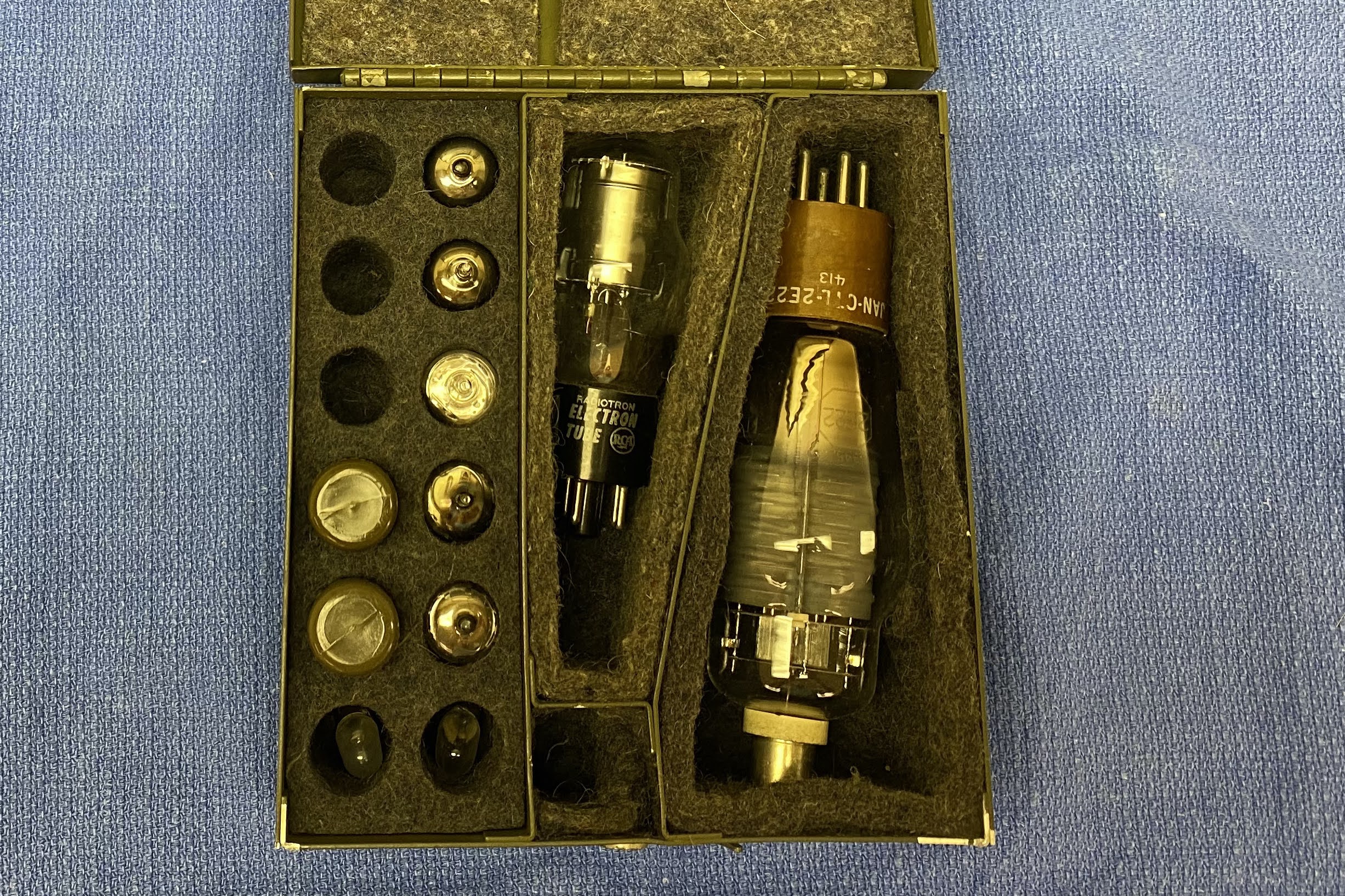
Spares
As a military radio, it was expected that repairs should be performed in the field when possible. The radio shipped with spare tubes for the receiver-transmitter, as well as spare tubes and vibrators for the DY-88 power supply.
More to come
In the few days I've had the AN/GRC-9 the only problems I've encountered have been related to the old DY-88 power supply. Old vibrators cans are generally seized up, as was the case with mine. Eventually mine became un-stuck after repeated applications of power but there are some methods to restore truly frozen ones using AC current and light bulbs (see Notes section below).
I've made about half a dozen contacts on the ham bands, including a 40m contact to a station in TX which is kinda DX for my locale. I've received nice signal reports. I've specifically asked stations about my "chirp" during QSOs and they've reported it as "not bad" and "charming". When operating from the VFO (master oscillator) rather than a crystal, the GRC-9 will "chirp". It was considered an acceptable design trade-off at the time. I've listened to the transmitter from a remote WebSDR station to hear the chirp for myself, and I agree that it isn't extreme and lends some character to the station. The unit does drift about 200 Hz during a QSO which I also think is quite acceptable for it's age. It's possible that if I spent more time in Send mode prior to a QSO to allow the transmitter tubes to warm up the drift might be lessened, but keeping the radio in Send mode puts quite a load on the power supply (both the 12v supplying the DY-88 and the human cranking the GN-58).
The RT-77 Telefunken receiver doesn't offer much in terms of selectivity and on a crowded band there's a lot of stations to contend with in the passband. The outboard CW filter deals with this nicely, but it is so narrow that when shifting from Send to Standby, the resulting frequency shift often throws the station I'm receiving out of the filter's passband, so that's a bit tricky.
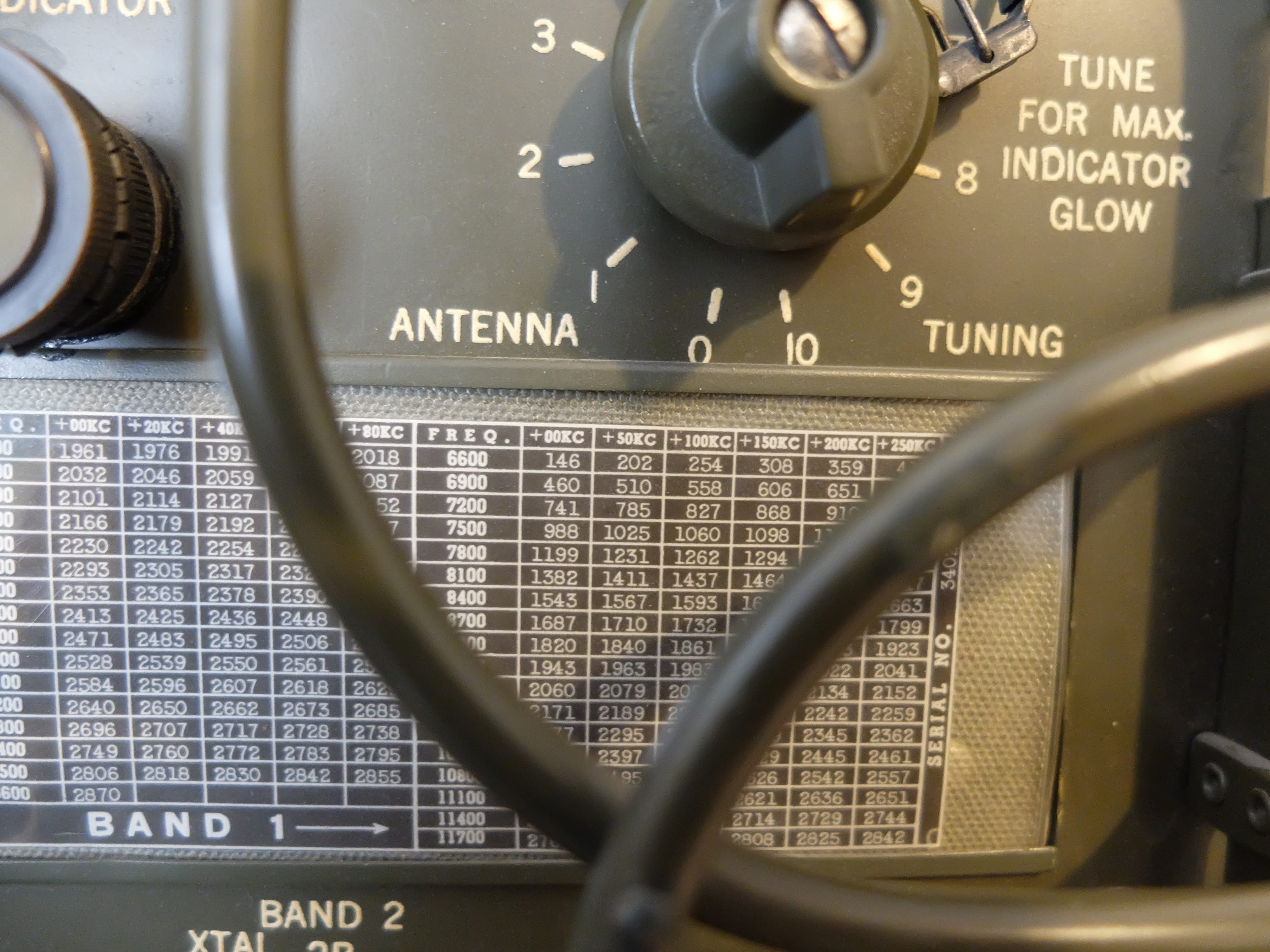
The receiver's tuning knob also is very coarse, in that fine adjustments are made by breathing on the knob. However it has zero backlash, which is amazing in a piece of equipment this old. The markings on the receiver are in 50 kHz intervals so the only way to really figure out where you are is to look at RBN for your spot.
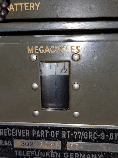 |
50 kHz spacing when reading the frequency on the receiver
Note the 7.2 is 7.200 MHz in the 40m band |
Images
Enjoy the pictures of the AN/GRC-9
Notes
Instructions for restoring a vibrator to operation
VB-1 and VB-7 are interchangable. I think I recall reading somewhere that VB-7 is a "lightweight" version of VB-1 but I won't swear to that.
The base is 4-pin, and the pin numbers are counted as on a vacuum tube with the same base. I wish I could post an image here without uploading it somewhere but if it's possible I've not figured out how to do it. The pins count clockwise from 1 to 4 looking at the bottom of the vibrator or the wiring side of the socket. The two large pins are 4 and 1 and the two small ones are 2 and 3.
There are two basic types of vibrators, called Series and Shunt. The Series type has a contact in series with the coil. VB-1, 7 and 16 are all Series types. I'll skip the Shunt type for now.
Pin 1 is common. Pin 4 is coil. Pin 2 is the NO (Normally Open) switching contact and Pin 3 is NC (Normally Closed). To test a VB-1/7, use an ohmmeter to check continuity from 1 to 4. If the reading is infinity, the coil could be open but this seldom happens. The problem is probably the vibrator contact. If the reading is a few ohms, connect +6 VDC to Pin 4 and -6 VDC to Pin 1. The vibrator should run. If it doesn't, most likely the contact is welded. About the only solution is to open up the vibrator, unstick the contact and try to burnish the burn marks out of the contact.
If the vibrator does run, go to the end of this screed and do the final test.
If the reading is infinity, here's how to use the two or three lamps to (usually) fix the vibrator. SAFETY NOTE: bear in mind you are dealing with either 120 or 220 VAC. If you jury rig the hookup, do all of your connections and disconnections with the "rig" not connected to the AC line. In other words, don't touch anything except the plug on the line cord or (if you go to that much trouble) the ON-OFF switch when the line cord is plugged in.
Connect the hot side of the AC line cord to one side of both lamps. Connect the ground side of the AC line cord to Pin 1 of the vibrator (or socket if you use one). Connect the other side of one of the lamps to Pin 4 and the other lamp to Pins 3 and 2. If you splurge and use three lamps, connect the "cold" side of the second and third lamps to Pins 2 and 3 respectively.
Check all the wiring and when satisfied all is OK, plug in the line cord. Probably nothing will happen immediately. Within a few minutes to a few hours lamp 1 should begin flickering and you should hear the vibrator hum. Run the test until the second lamp begins to flicker or until both the 2nd and 3rd lamps flicker.
If you are only using two lamps, when the 2nd lamp begins to flicker, wait 1 or 2 minutes then remove power (unplug the line cord). Connect the 2nd lamp only to Pin 2 and plug in the line cord. If the 2nd lamp flickers, remove power, move the 2nd lamp connection to Pin 3 and apply power. In either case (with the 2nd lamp now connected to pin 2 or 3 only), let the test run until the 2nd lamp again flickers.
For a final test, connect one lamp to Pin 2 and one to Pin 3. Connect 6 VDC to Pins 4 and 1. With the vibrator vibrating apply power to the two lamps. They should flicker alternately. Note that for this test, either use a 6 volt battery or a 6 VDC supply with both outputs not grounded. I wouldn't try to use the battery in the Jeep just in case you mis-identify which side of the line cord is grounded and which is hot.
Although a vibrator that is going to be fixed by this procedure will usually begin to work after say no more than half an hour, I have seen it take several hours. So if I have one that didn't start working fairly quickly, I'll let the test run up to about 8 hours max (or overnight) before giving up.
Robert
Gunner
USN Retired
MVPA 9480

 AN/GRC-9 aka “Angry Nine”


 HamRadioAuctions
 Reliance Antennas
 Enigma Shop

 R&L Electronics
 antennas.us
 QRV
QRV
Thanks for introducing this heavy parts. It’s an interesting part of the history. In 1967 I assembled military radios in the German AEG-Factory. In this time radium was no longer used. This radios were made for the German Bundeswehr.
73 and greetings from Berlin
Manfred
Thanks for the interesting report and the nice Pictures.
1971 I was in the Austrian Army and worked with this Rig, mounted in a Car.
Did enjoy to work CW.
73 de Harald OE3HOI
Very interesting article! Thanks for sharing and all the pictures!
73, Stephen w4tol
i thank you for the info i am looking for a AN/GRC10 if anyone knows where one is at please let no where i can get/find 1.73 RONNIE
Nice job my friend. I wish you succeed for ever. Good luck. 73.
THE BEST !!! SITE ABOUT GRC-9.
Hallo ich würde ein Kabel CX-2031 brauchen für meinen R-77! Weiß jemand wo ich eins bekomme!`? Danke NIK
Thank you Richard for the very nice article.
I had in charge this radio during my service in italian army in 1981 .
Basically they were used as company level radio but GRC9 needed trained operators then at time along the nord-east border of Italy they were on the way to be replaced by more simple to use set as AN/PRC-77 possibly with power amplifier added .
Very interesting the info about alpha-radioactivity I was not aware of in 1981 :-).
Steven Saslow k7ew Portland Oregon usa
Valuing the GRC-9 article!
Hoping to locate similar on the RUP-4! I am working on what appears to be a complete one. RX is a tyransistor version. TX uses a very interesting dual tetrode. Would dearly like a functional GN58/ the handcranking gen, complete with the eat + legs apparatus, etc… tnx es 73!
Very complete write up, saw a lot I did
Dutch Army used these indeed, my dad (1934-2005) always mentioned the Angry Nine to us when he talked of his Army days, way back in 1953 when he was enlisted as a radio operator with the engineers.
Sadly I have no recollection of him telling anything that could be of use to you. Thank you for this page, it’s good to have an idea of what he was talking about.
Spiegazioni molto complete ed esaustive su questa splendida radio,
grazie