 |
 Small loop antenna for HF listening
I built this antenna a few years ago and it is about time I posted details about it on this blog.
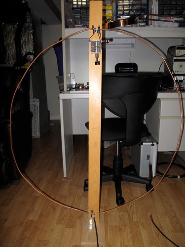
This is a small loop, that is the length is ≤0.1 of a wavelength, and designed for receive only, not transmitting. The loop is a little more oval than round with the narrower diameter being 36″ and the wider diameter being 40″. A transformer is used to collect the signal and pass it via coax to the receiver. The antenna shown and described here tunes from around 3 MHz to 18 MHz. So it covers 80m through to 20m and of course the broadcast bands in between those frequencies too.
The schematic of the loop is shown below.

Schematic of the small loop antenna
The main loop is composed of ¼” copper tubing (available from hardware and plumbing stores). The advantage of this type of tubing is that is easy to bend into a set shape and it maintains that shape with just a few fixing points. If a wire loop was to be made it would require some sort of frame to retain the loop shape.
The capacitor is a variable capacitor from a receiver. I have not measured the capacitance but I suspect both sections together give a maximum of 300 to 400pF. To increase the range of the tuning of the loop I included a switch to allow either one or both of the dual stage capacitor to be included in the loop. The picture below shows the top mounting of the loop, the variable capacitor and the switch. To make easy connection to the capacitor, the copper was squeezed closed at the ends and holes were drilled for bolts. Ring or spade-end connectors can be used to connect wires from the capacitor to the copper tube, and held in place with nuts and bolts.
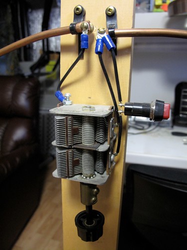
Note that the copper ends of the loop should not contact each other. They are close in my loop, because of the cable tie mountings on the pine wood, but they do not touch. Electrical connectivity is through the capacitor. To prevent any ‘hand capacitance’ effects when tuning (and hence tuning issues) I added a non-conducting shaft on the capacitor (you can see the brass shaft connector). In my loop the two capacitor sections are joined in parallel to increase the capacitance. The switch can switch out one section, so decreasing the minimum capacitance and increasing the upper frequency that can be tuned. A single stage capacitor, without a switch, will do fine, but the higher the capacitance the better.
At the opposite end of the loop a T50-43 toroid has been threaded onto the copper tube. The toroid has five turns of enameled wire wound on it and it slides easily over the copper. The copper loop now makes one turn on the loop and the five turns of wire on the ferrite toroid makes the transformer (as shown on the schematic). This arrangement can be seen below.
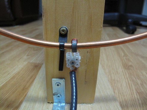
The enameled wire ends have had the enamel removed (only the ends) and have been tinned with solder before inserted into the electric wire block, which allows connection to the RG-58 cable. At the end of the cable add whatever connector you need for your receiver. The photograph also shows the simple L bracket arrangement for holding the pine plank upright on a simple plinth (a small piece of off-cut maple) large enough to stop the loop from toppling over..
The use of the electric connector block is not ideal I find (the enameled wire is too thin) and in future I will probably make something suitable out of some unetched copper circuit board and solder the wire and coax directly to the board.
I am sure there is room for experimentation with the type of mix of the toroid, as well as the number of turns of the enameled wire. My loop worked satisfactorily so I left it as it is.
How does it perform? Well I find it always surprises me how well it works for about 10ft of copper tube in a loop, a capacitor and a transformer. I use this in my basement and can easily tune in stronger stations on the bands. The high Q of small loop antennas rejects strong out of band stations that can bleed-through in more conventional random wire or even dipole antennas, so improving reception performance. When using the antenna you must tune to the frequency or band of interest and then adjust the loop’s capacitor to tune the loop to the same frequency. You will hear either a rise in signal strength of a station or background noise if there is no station on frequency. It is simple to use and it is surprising how it can increase the received signal.
Below are a few recordings made using the loop antenna. The receiver was the old but excellent Yaesu FRG-7, which for the purpose of this demonstration serves well as a general good receiver, although as you will hear the filtering is wide (‘barn-door’ wide springs to mind). For each of the recordings I tuned the receiver to the required frequency and adjusted its pre-selector for maximum signal. What you will hear in each case is the signal and then I will detune the loop one way, then tune it back through the peak to the other side and then returning to the peak of the signal. Recordings were made with an MP3 recorder place in-front of the receiver’s speaker, so you hear what the listener would hear. You should remember this is a 10ft circumference loop in my basement, NOT 100+ft of wire 50ft off the ground.
Small loops are directional to the signal source so if you use one you should experiment by turning it. It may be the HF frequency, or the fact that my antenna is below ground level, but I have noticed not too much of a difference when the loop is turned in orientation. That said, other small loops I have built for the AM broadcast frequencies, or medium wave, do show a stronger directional nature.
If you want to learn more about small loop antennas I recommend Joe Carr’s Loop Antenna Handbook, published by Universal Radio. That book describes many loops, both large and small and is well worth the read if you enjoy antenna design. This loop design is not from the book, but I used concepts and theory from it. The idea of using the copper tubing and the toroid transformer slid onto the copper was my own, although it may not be a novel idea and could have been reported before.
Let me know with a comment if you build and experiment with such an antenna. Share your findings with other readers.


![]()
One Response to “Small loop antenna for HF listening”
 Ham Radio Deluxe |
 W5SWL Electronics |
 Ham Radio Prep |
 KB3IFH QSL Cards  Hip Ham Shirts  HamRadioAuctions HamRadioAuctions Reliance Antennas Reliance Antennas Enigma Shop Enigma Shop |  morseDX  Ni4L Antennas  R&L Electronics R&L Electronics antennas.us antennas.us QRV QRV |
- Matt W1MST, Managing Editor

This brought back memories. In my younger years (I’m turning 44) I made three of them, covering 500 kHz to 21 MHz. The loop was made of coax and the coupling was done with a small turn of coax soldered to the big loop. Worked fine, but sometimes it lacked “punch” and I still used my long wire for DX purposes. But they sure are goo noise eliminators.
I still have a FRG-7 running too. Those were the days when they still made “real” radio’s with VFOs and big metal cabinets. Oh no, I’m getting sentimental again, hi hi.
I’m moving house and after moving I plan get out my medium wave loop again, modify it to work on 160 meters and build a separate helical for transmitting. Can’t wait to get back down low.
73 and keep on writing.
Hans