 |
 Low cost earth-mode beacons?
G1KQH has found some very low cost TDA2003 ICs. I use one of these in my VLF beacon shown in my RSGB RadCom article and on my website. Best range is just short of 6km by “utilities assisted” earth-mode. When fitter again (currently I am not allowed to drive and I am still too clumsy when on my feet and moving because of my brain bleed last year) I intend to continue my VLF experiments. I have used these ICs at 8.97kHz, twice, and sub-multiples of that frequency. Beyond 20kHz would be outside their spec limits, but they may still work?
| G3XBM 5W VLFearth-mode CW/QRSS beacon |
Evening Roger,Used in your LF PA 10p each nuts!Or you can buy in 10s @ 16p each inc delivery!
Banggood sounds Chinese. I have no idea if these are genuine parts or not. They are advertised as 10W car radio audio parts.
Roger Lapthorn, G3XBM, is a regular contributor to AmateurRadio.com and writes from Cambridge, England.
Amateur Radio Newsline Report 1936 September 19 2014
- Qatar will include ham radio in an upcoming 2016 geosat launch
- More information on the restructuring of the UK ham radio rules
- Philippine hams once again respond as a typhoon makes landfall
- W5KUB announces live coverage of the K6H operating event
- Soon to be space traveler Sarah Brightman starts training in January
DX from Old Hill
Judy and I rode our bikes along the Pemigewasset River in Old Hill. I stopped on a knoll overlooking the river for 15 minutes and worked Belgium, Moldova, W1AW/4 in NC and Germany.

The day was fine, but a bit cool and breezy. It definitely feels like fall is approaching. Every now and then the scent of wild apples would fill our nostrils as we peddled along. Yellow leaves lay on the path. Wild asters dotted the lane way.
On the knoll I tossed my line over a pine branch and hooked up the KX3. I started out on 17 meters. Right away I worked Pat ON7PQ in Belgium. He was 599 and gave me a 569. Then… another quick contact with
Moldova… ER3MM, Victor. He gave me a 449.

Then I switched to 20 meters and heard W1AW/4 in North Carolina booming in. I made the contact easily.

I switched to 15 meters for one more QSO. Hans DL8MCG was calling CQ and I answered him. I wasn’t strong… barely 539, but we had a nice chat. “UR FB with 5W,” he sent when I told him I was QRP. Hans was running 500 watts to a vertical.
I packed up and joined Judy who was knitting in the sun farther down the lane.

The crickets are singing a new song now. It’s the song of cooler days and the coming of winter.
Jim Cluett, W1PID, is a regular contributor to AmateurRadio.com and writes from New Hampshire, USA. Contact him at [email protected].
Take time to listen it pays off.
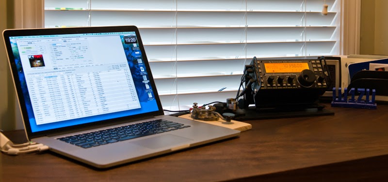 |
| W1ZU's home setup. |
Mike Weir, VE9KK, is a regular contributor to AmateurRadio.com and writes from New Brunswick, Canada. Contact him at [email protected].
CW Op’s Mini-CWT Contest – Results!
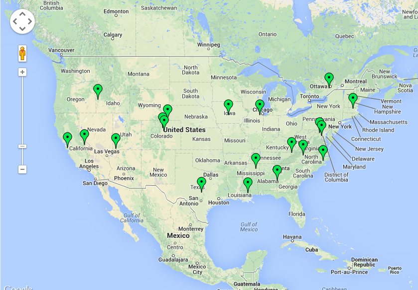 |
| Map of Stations Worked in the Mini-CWT |
Every Wednesday the CW Operators Club has a mini contest called the MINI-CWT. It runs for one hour – 10:00 pm to 11:00 pm local time here in Kansas. This time works great for me – kids are in bed, and house chores are complete!
This is the second time I have operated this contest and I had a blast. Conditions on 20 meters were awful here – I didn’t hear one signal on the band except some digital signals. So I immediately went to 40 meters and stayed there for the duration.
All told I worked 20 stations, for a score of 400 points- all stateside with one except being Canada. I was really happy with this result!
When I worked the June contest I only worked 6 stations for a total score of 36 points, so I greatly improved tonight!
You can see a map of the locations of the stations I worked during the contest last night. I created this using a site that I found that is really cool. It is QSOMap.org – and it lets you upload an ADIF file and it maps the locations.
I really enjoy working contests. Running QRP it gives you the opportunity to work some really good operators that also have excellent antennas. Everyone I called last night, I worked!
Thanks to all the ops that pulled my signal out – you made it a fun night!
Also be sure and check out my N0HYD YouTube Channel!
Burke Jones, NØHYD, is a regular contributor to AmateurRadio.com and writes from Kansas, USA. Contact him at [email protected].
CW Op’s Mini-CWT Contest – Results!
|
| Map of Stations Worked in the Mini-CWT |
Every Wednesday the CW Operators Club has a mini contest called the MINI-CWT. It runs for one hour – 10:00 pm to 11:00 pm local time here in Kansas. This time works great for me – kids are in bed, and house chores are complete!
This is the second time I have operated this contest and I had a blast. Conditions on 20 meters were awful here – I didn’t hear one signal on the band except some digital signals. So I immediately went to 40 meters and stayed there for the duration.
All told I worked 20 stations, for a score of 400 points- all stateside with one except being Canada. I was really happy with this result!
When I worked the June contest I only worked 6 stations for a total score of 36 points, so I greatly improved tonight!
You can see a map of the locations of the stations I worked during the contest last night. I created this using a site that I found that is really cool. It is QSOMap.org – and it lets you upload an ADIF file and it maps the locations.
I really enjoy working contests. Running QRP it gives you the opportunity to work some really good operators that also have excellent antennas. Everyone I called last night, I worked!
Thanks to all the ops that pulled my signal out – you made it a fun night!
Also be sure and check out my N0HYD YouTube Channel!
Burke Jones, NØHYD, is a regular contributor to AmateurRadio.com and writes from Kansas, USA. Contact him at [email protected].
September, 2014 – QSL Card Giveaway Winner Announcement
And the winner of 500 free full-color QSL cards is…
Peter VK6IS
Australia
Congratulations to Peter and thank you to everyone who entered. Keep a lookout for more great giveaways! As always, thank you to KB3IFH QSL Cards for generously sponsoring this contest. Don’t forget to check out Randy’s website the next time you need new QSL cards!
73 Matt W1MST
Matt Thomas, W1MST, is the managing editor of AmateurRadio.com. Contact him at [email protected].
 Ham Radio Deluxe |
 W5SWL Electronics |
 Ham Radio Prep |
 KB3IFH QSL Cards  Hip Ham Shirts  HamRadioAuctions HamRadioAuctions Reliance Antennas Reliance Antennas Enigma Shop Enigma Shop |  morseDX  Ni4L Antennas  R&L Electronics R&L Electronics antennas.us antennas.us QRV QRV |
- Matt W1MST, Managing Editor
