 |
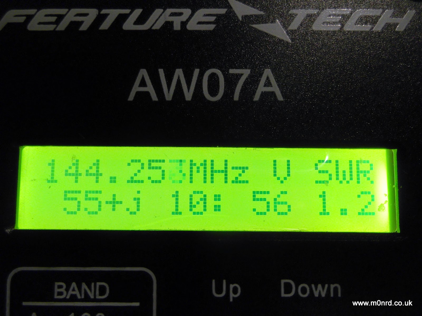
 Feature Tech AW07A Antenna Analyser – First impressions
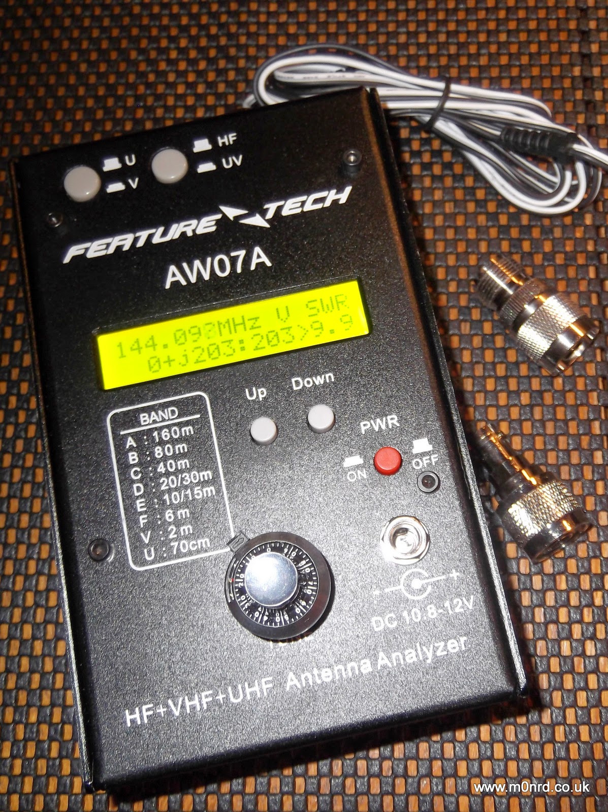
It is about the size of a thick paperback book and is a powder coated steel case similar in style to that used by MFJ equipment, indeed the MFJ-266 analyser appears to be a re-badged version albeit for a lot more money than this unit can be purchased.
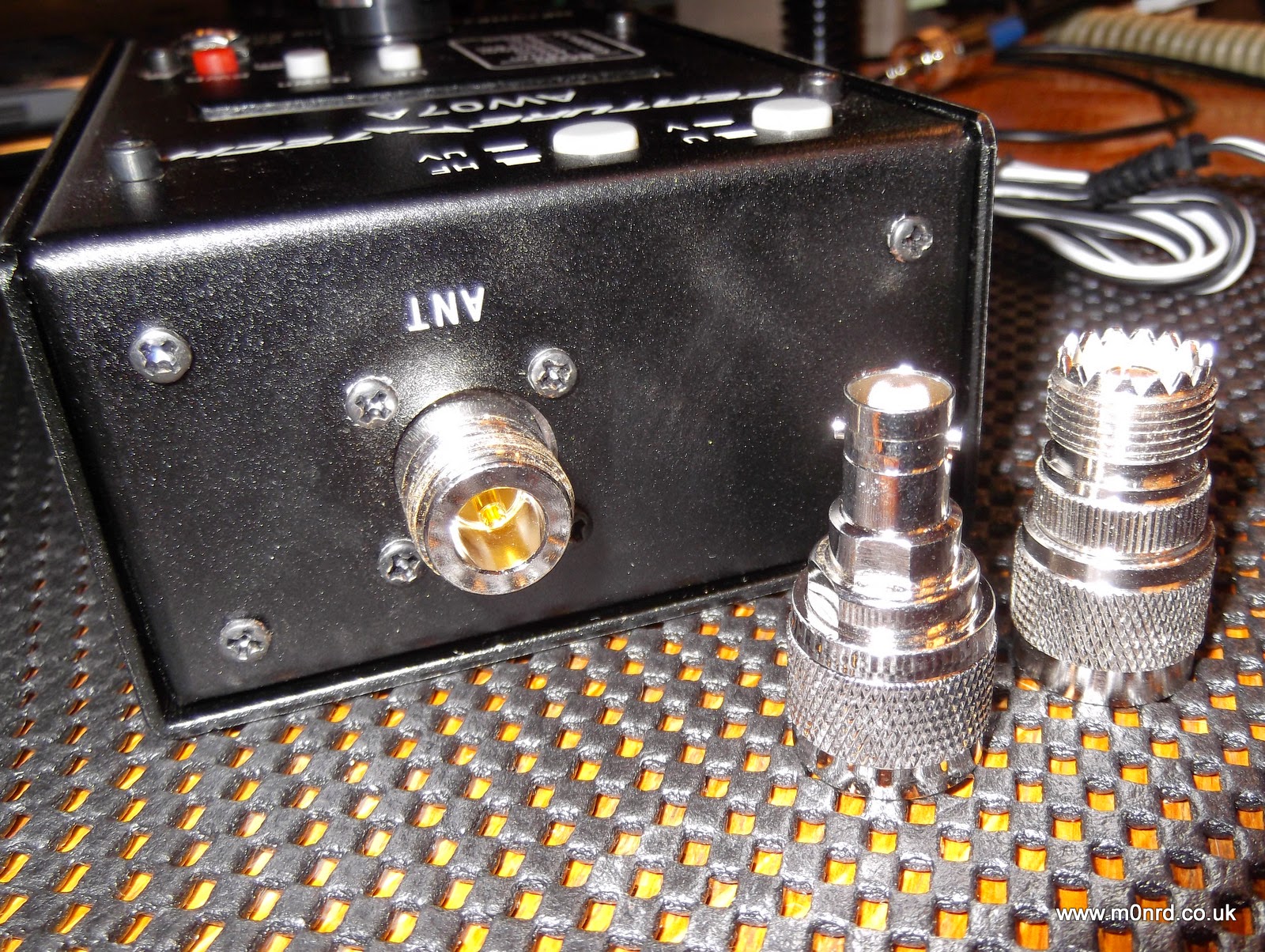
It can be powered by batteries fitted internally or by an external supply and is supplied with a power cable for connection to an external supply, mine was white/black rather than the normal red/black cable. It has a N-Type socket for the antenna and comes with two adapters for PL259 and BNC connectors.
It has a power button near the external power socket, two buttons on the top select HF and VHF/UHF operation and two other buttons marked UP and DOWN to select operating mode and/or the frequency band being used. Unfortunately one thing it doesn't come with is a manual but a copy can be downloaded from QSL.net or a slightly different version from the manufacturers website. But I actually downloaded the manual for the MFJ-226 has it is much more detailed.
The front panel decal and manual state it can be run from 10.8-12V, in fact the manual states it should ideally be less than 12.5V and no more than 13V. While doing some research I found the reason for this limitation hidden away on this aliexpress webpage "Avoid higher than 13V power supply circuit for the UV segment may be damaged due to excessive power dissipation." So this would seem to rule out using a standard 13.8V power supply.
It can be fitted internally with eight AA batteries and this is the way most people would use as it offers portability. Removing four screws allows access to the battery compartment and the internals electronics seem well built.
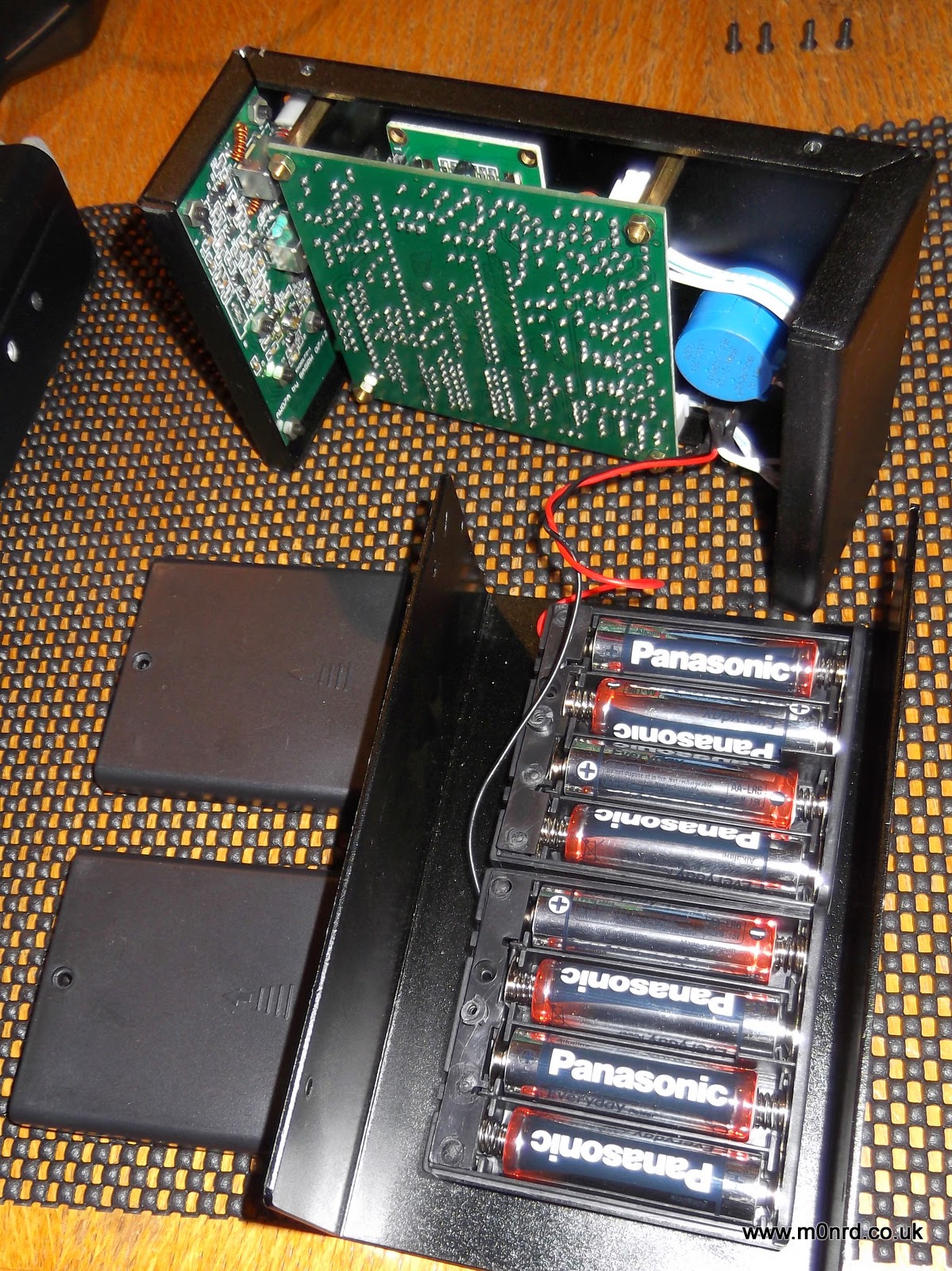
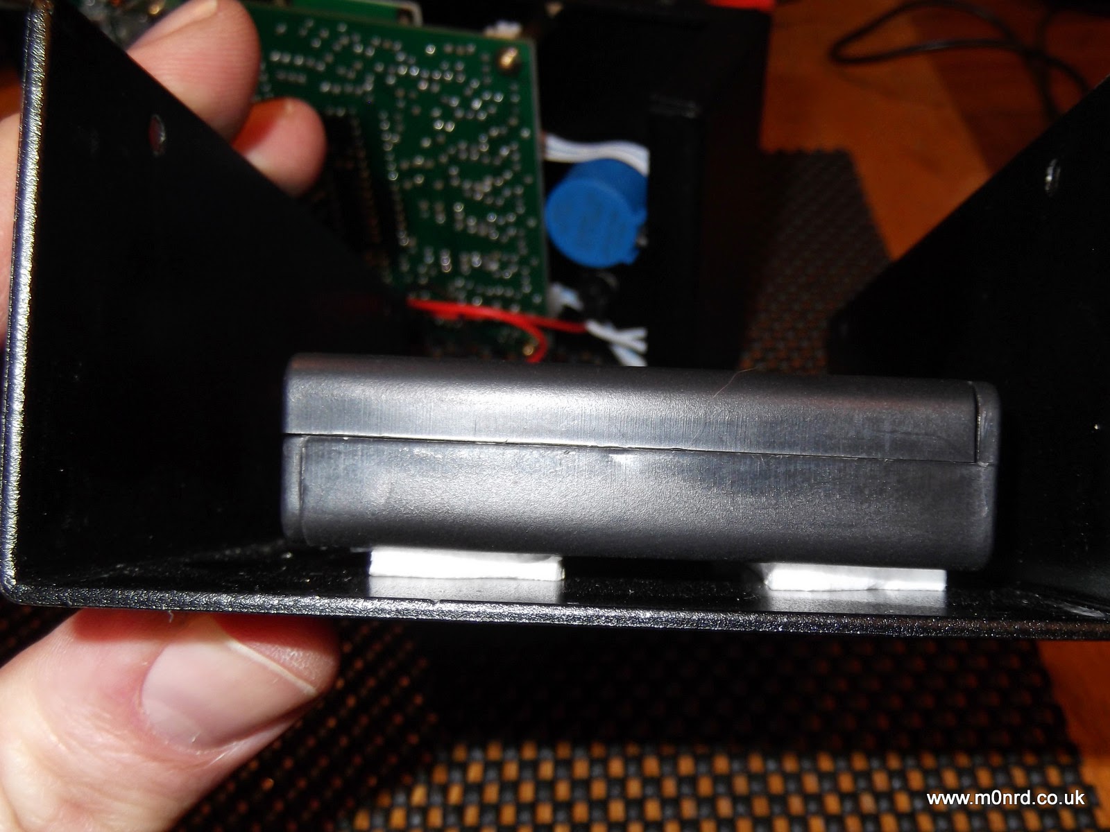
It takes eight AA batteries, in two boxes. The battery boxes have lids secured with a small screws and are fixed to the case using simple sticky pads, while secure at the moment I can imagine in time the adhesive could dry-out and become unstuck leaving the battery boxes loose inside the unit.
The display is a simple two line LCD with an optional bright back light which can be turned on during the power up sequence. The display shows the battery or supply voltage and pressing Down puts the unit into a frequency counter mode. Pressing Up puts into the antenna analyser mode.

In the analyser mode it is a simple case of selecting the HF, VHF or UHF mode. VHF works from 85-185MHz, UHF is 300-390MHz, the HF is split into six overlapping bands A: 1.5-2.7 MHz B: 2.5-4.8 MHz C: 4.6-9.6 MHz D: 8.5-18.7 MHz E: 17.3-39 MHz F: 33.7-71 MHz selected using the Up/Down buttons.
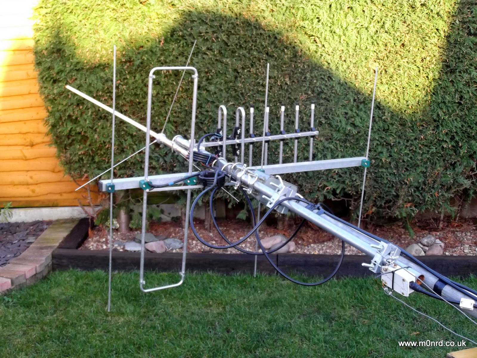
Turning the vernier tuning knob adjusts the generated frequency the antenna is being tested against. I connected the analyser to my 2m YAGI antenna and turned the knob to find the lowest SWR

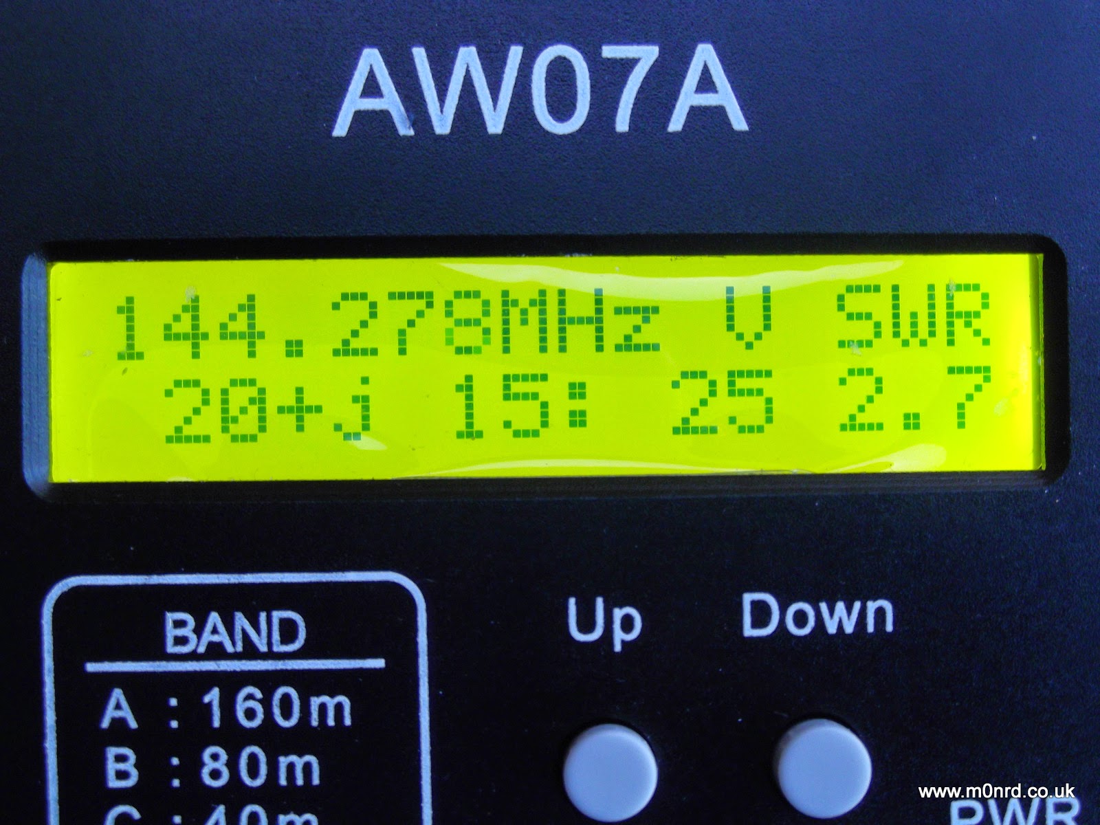
The manual describes what is being displayed (on UHF just the SWR is shown)
“139.763 MHz” is the frequency
“V “is the band (A,B,C,D,E,F in HF, V in VHF and U in UHF)
The bottom row shows the complex impedance Z = R + jX, so on this screen
“41” represents R = 41 ohms the resistive component
“18:” represents the reactance component value, jX = 18 ohms
“45” is the overall complex impedance magnitude Z = 45 ohms
“1.5” is the SWR value
As you can see for a 2m antenna something isn't quite right! The antennas were down due to last weeks strong winds so I was taking the opportunity to do some maintenance and tweaking of the 2m antenna since I'd seen an increase in the SWR during recent UKAC contests. I had suspected feeder issues, possible water ingress but I tried a dummy load at the antenna end but that read as expected (Z=50ohms) and metering the continuity of the feeder showed no issues, it just seemed to be resonant at too low a frequency.
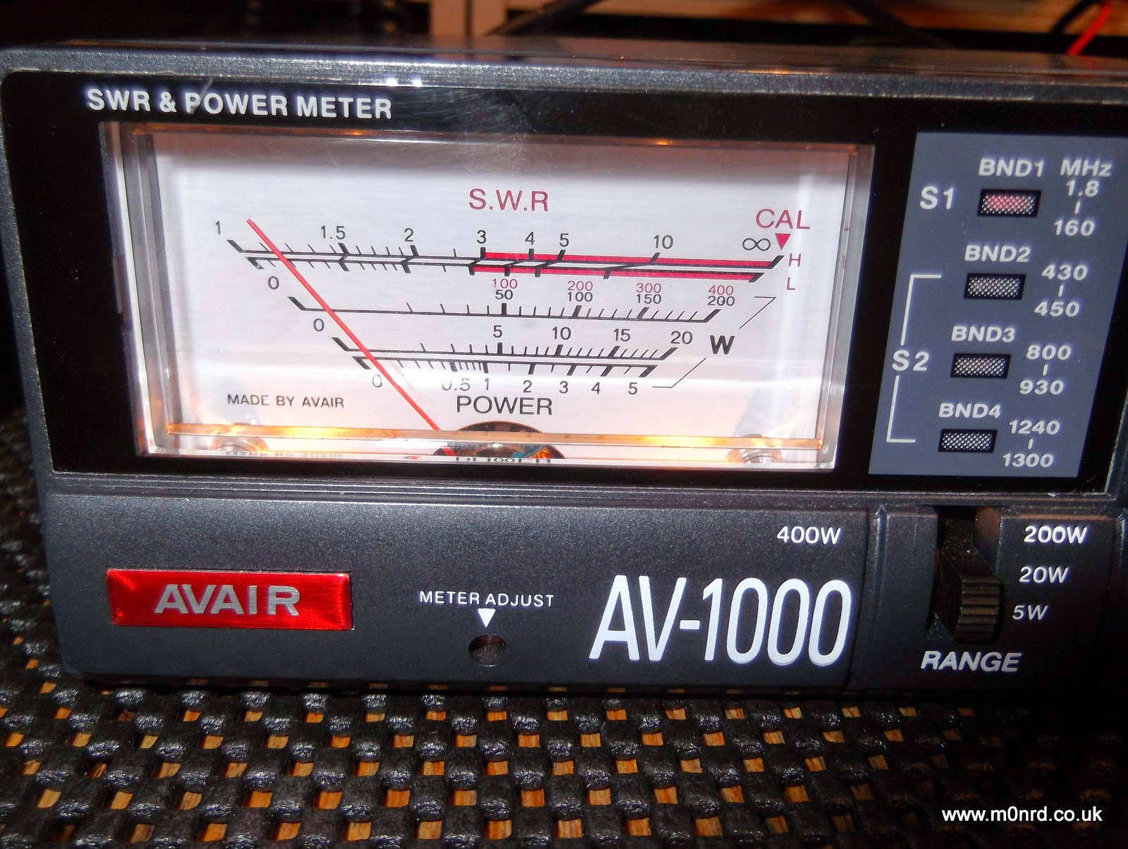
The analyser confirmed what I'd observed with a normal SWR/Power meter a higher than desired SWR in the middle of the SSB section of the 2m band.
Unfortunately I was unable to get it any lower than 2.5 and most adjustments seemed to increase the SWR. For peace of mind I double checked the analyser by swapping the feeder on to the 2m/70cm collinear and that was spot on
again I double checked the SWR readings back in the shack using the normal meter
While I try to sort out the antenna issue I can say the analyser seems to do its job well. The tuning knob is a little twitchy and has a bit of play which makes setting the frequency accurately a little harder than it should be but hopefully that might improve with use.
The unit also has other functions none of which I have used yet but it is bonus to have some useful test functions available in the shack.
The AW07A can be used as an inductance/capacitance meter by powering it up with the U or D button held down. The inductance or capacitance of a component fitted across the antenna socket is then displayed and this can be done for any test frequency by selecting the band and turning the tuning knob.
As I mentioned earlier the unit can also function as a frequency counter that can measure signals between 1 and 500 MHz and can be used to give an indication of relative RF field strength. A signal source or an external antenna that yields a usable signal level may be connected to the analyser’s antenna jack. The usable signal range is quoted as -20dBm (30mV) to +10dBm (1V). Note that the display reading is a RMS value.
Obviously in the antenna analyser mode the output which is approximately 2V in magnitude can be used as a signal source, with 20dB of second harmonic suppression.
The MFJ manual goes into some detail of how this all works and how to use the analyser for a number of common tasks such as checking baluns, making 1/4wave stubs or measuring velocity factor of coax.
While the AW07A has some obvious shortcomings and may not be a precision device I am impressed with it and what it can seemingly do. It is shame about the lack of a manual but I am not sure getting one is justification for the premium price of the near identical MFJ unit.
Andrew Garratt, MØNRD, is a regular contributor to AmateurRadio.com and writes from East Midlands, England. Contact him at [email protected].
Yet More 630m Activity!
 Another VE7 has been bitten by the 630m bug ... well, intrigued enough to start building a station. On the weekend VA7MM (Mark), in Port Coquitlam, asked if I could take a listen for his low power signal. I'll let Mark describe his setup:
"My transmitter is a HP8640B signal generator. It is stable and has 1 Hz
frequency readout with maximum RF output of 20dBm. CW keying was done by latching the antenna on and off of the HP8640B. The latching relay was driven by the send relay in an IC-746Pro running with full break-in CW
turned on. A 1N914 switching diode was installed across the relay coil as
the back EMF from the relay was measured using my oscilloscope to be a +50V spike. This effectively attenuates the voltage spike. A good safety
precaution before installation.
A second HF radio, an IC-7600, was on a separate wire antenna for receive
only and with Spectran running for signal analysis.
In the final setup three series coils totalling 330 uH and a series of
parallel variable capacitors adjusted to about 1000 pf were installed in a
series resonance circuit outdoors at the base of a sloping dipole with the
apex at about 40 m. The antenna outside shielded and center conductor were connected effectively making the antenna a vertical. There was no impedance matching. One ground radial about 300' long was laid out laying on the surface of the ground. The resonance circuit was tuned using a combination of a Blackberry Z10 smart phone real time video chat link of Spectran from the ham shack in combination with a portable VHF audio feed to both visually and audibly tune the resonance circuit for maximum output. I tried a parallel resonance circuit but it did not work.
The straight line distances between QTHs from Google are:
VA7MM to VE7SL: 60 km
VA7MM to VE7CNF: 10 km
Amazing that a piece of lab equipment can be enabled with a few hours of
tinkering to transmit a signal on the 630 m band a distance of 60 km.
Thanks for the first 630 m band contacts. It was fun. Now I'm going to start planning a permanent capability on 630 m."
Mark's setup reminds me of a Rube Goldberg machine but it all worked well enough for him to put out a solid 559 signal at 60km distance and provide his first official 630m contact.
As of today, the following VE7 stations have now made two-way contacts on the new band:
VE7BDQ
VE7CNF
VE7SL
VA7JX
VA7MM
It would be great to see some activity from northern BC, VE6, VE5 and points further to the east. How about it fellas?
Steve McDonald, VE7SL, is a regular contributor to AmateurRadio.com and writes from British Columbia, Canada. Contact him at [email protected].
First thoughts of the MF500B Multimeter
For the cost of £20 ($30 US) it looks and feels like a more expensive meter, but do looks deceive?
The movement is good, you can tell this by moving it from left to right and noting that it is well damped and returns slowly to it zero position, the range selector knobs and switching has a professional feel and click into position.
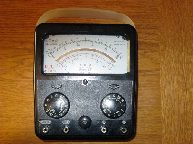
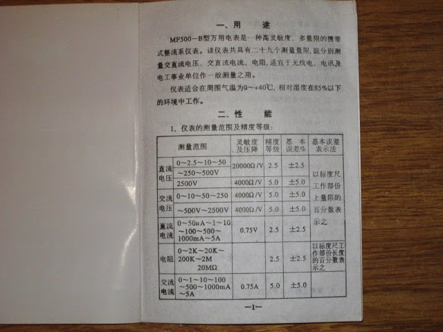
The manual isn't up to much, as 99% of it is written in Chinese. I am able to decipher that it is an Industry standard 20'000 Ohms/V meter on DC +/- 2.5% , except 2500V @ 4000 Ohm/V. On AC ranges it is 2500 Ohms/V +/- 5% accuracy. DC Current (I) is +/- 2.5% & AC Current +/- 5%.
Ohms measurement +/- 2.5% accuracy.
Batteries required for Ohms ranges are a 9V PP3(6F23), and one C cell, although an AA will fit to get you away.
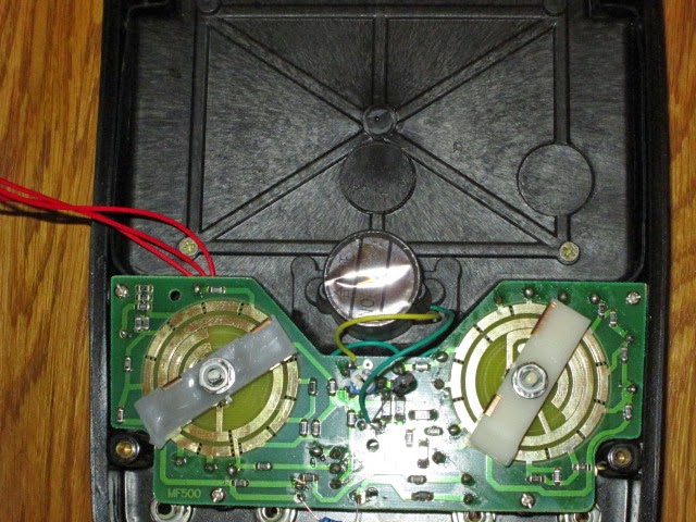
I was excited like a little boy with a new toy to get the back cover open to give it a good looking over. Turning it upside down onto its face, are 4 sturdy anodised screws that are covered over by plastic plugs in each corner of the case, these easily pop out with small screwdriver forcing them up.
The rear cover then splits away in half, leaving the wires attached from the battery box to the main PCB. I was slightly disappointed by its SMT design, but I accept most things are done this way these days. The odd leaded capacitor and resistor tagged onto the rear of the board did remind me of designs of past years, switching is direct onto the gold plating onto the board. The PCB looks good, there were no signs of any dry joints, however I could not see any fuses for protection, nothing is highlighted in the schematic, what could one really expect for the money? Prehaps I am just used to my ageing AVO 8 with its popout safety breaker.
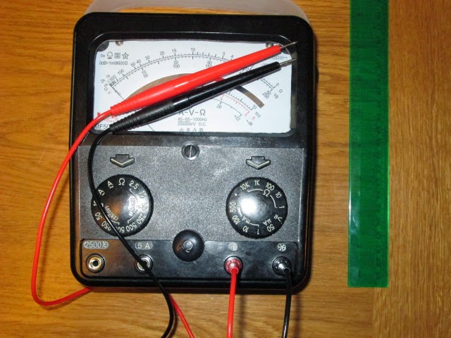
If you note from the specification the meter does cover 2.5KV! However, I would certainly not like to be on the end of it with the test probes provided (two pairs included), my BIC biro has more plastic on its case than these suicidal leads that are certainly not up to the job! A purchase of a good pair of leads to CAT III spec is a must!
Conclusion so far: Sturdy well made case, Meter movement has the looks and feel of a professional movement costing 10 times more. If you are a novice coming into the hobby and you can't read Chinese don't blame me if you can't understand the manual how to drive it? Anyone else who has been part of the hobby game or the field should have no problem sorting it out. May not be serviceable if you blow or damage parts on the board if you select and use it on the wrong range? Requires a decent set of test leads and probes!
Testing to be concluded further down the Blog.
Steve, G1KQH, is a regular contributor to AmateurRadio.com and writes from England. Contact him at [email protected].
From Bill’s hospital bed: January 15, 2015
Not much new to report. I had hoped to be home by now but my doctors say otherwise.
The two ribs are healing nicely, but as long as I am here they want me to do a few weeks of cardio re-hab before they sign me clear, but I have no idea as to how long this will take. (For those not aware I been a sufferer of Coronary Artery Disease since about 1983 and went through an out patient cardio rehab program back then.)
For now, the full length ARNewsline newscast remains down. am looking to find a volunteer with a background in Broadcast Journalism / Radio News Production and who can devote about a day a week to come aboard as a co-producer with me. I can easily write stories and scripts from here, but doing the editing, post production, etc. would be all but impossible from this environment.
In the meantime, a compact (about 6 minute) audio/video version will continue to be produced by Don Wilbanks, AE5DW, and will be posted to several locations including our Facebook page, our website (www.arnewslinre.org) and included on the weekly show Ham Nation (twit.tv/hn).
My sincere thanks to both Don and out Webmaster Kevin Trotman N5PRE, for keeping the various entities as up to date as possible with the latest breaking news and I can assure you that the full length newscast (both audio and text) will be back -- hopefully in the very near future.
Also a big thank you to Todd Hitzeroth N6ZXJ who lent me this laptop when mine lost its had drive two days into this unexpected "forced vacation" and to Dave Booth, KC6WFS, who is repairing the machine with its clickety-clacking drive.
Last, but by no means least, my sincere thank you to all who have offer your prayers and e-mailed and/or called with your get well wishes. All are very much appreciated.
Keep an eye on the ARNewsline website and Facebook page for the latest updates.
de
Bill P. / WA6ITF
Lightwave Article From ‘TCA’
 |
| VE7SL Backyard Test |
Steve McDonald, VE7SL, is a regular contributor to AmateurRadio.com and writes from British Columbia, Canada. Contact him at [email protected].
Bouncing a signal through the NO-44 satellite
One of my favourite tweeters on radio matters is Patrick WD9EWK Patrick is a keen member of AMSAT and the wider amateur satellite community. Just recently, Patrick has been experimenting sending APRS packets through the old NO-44 satellite.
NO-44 or PCSAT is one of those satellites that is in its’, er, twilight years. The battery failed some time ago and now the satellite operates when the solar panels can supply it enough power to make it go. It was and is, an APRS digipeater in space. Recently, Patrick has shown making keyboard to keyboard APRS QSOs through NO-44 as well as simply digipeating his own signals. Patrick had used his Kenwood APRS enabled handheld and his handheld Arrow antenna.
I thought I should try! I noticed a pass this morning where NO-44 was in sun all the way up over the South Atlantic before passing directly overhead us here in the UK, so got the ‘usual’ ISS packet setup going, using the V-2000 vertical and wondered if I would hear anything.
All was quiet until I calculated the satellite was almost directly overhead and I send a packet, with the unproto path set to PCSAT via W3ADO-1 To my surprise, I heard a weak packet. Too weak for me to decode, but as I discovered later, thanks to Paul N8HM, the ON7EQ-1 gateway heard it and retransmitted it and plotted me on the map you’ll see below
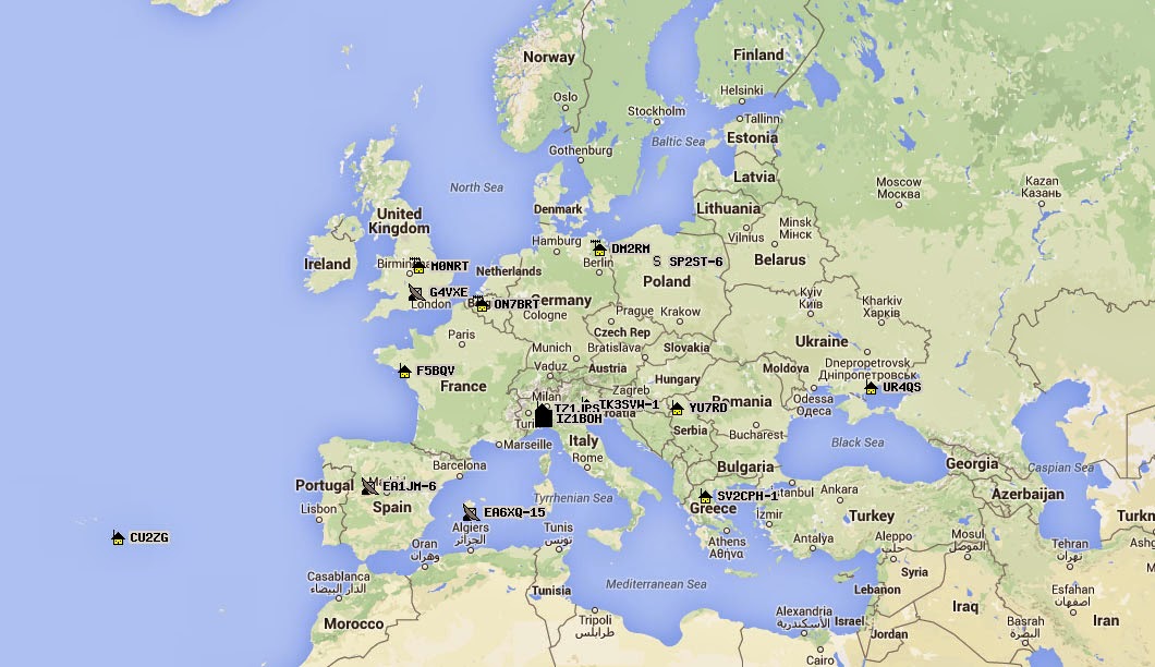
Tim Kirby, G4VXE, is a regular contributor to AmateurRadio.com and writes from Oxfordshire, England. Contact him at [email protected].
Bouncing a signal through the NO-44 satellite
One of my favourite tweeters on radio matters is Patrick WD9EWK Patrick is a keen member of AMSAT and the wider amateur satellite community. Just recently, Patrick has been experimenting sending APRS packets through the old NO-44 satellite.
NO-44 or PCSAT is one of those satellites that is in its’, er, twilight years. The battery failed some time ago and now the satellite operates when the solar panels can supply it enough power to make it go. It was and is, an APRS digipeater in space. Recently, Patrick has shown making keyboard to keyboard APRS QSOs through NO-44 as well as simply digipeating his own signals. Patrick had used his Kenwood APRS enabled handheld and his handheld Arrow antenna.
I thought I should try! I noticed a pass this morning where NO-44 was in sun all the way up over the South Atlantic before passing directly overhead us here in the UK, so got the ‘usual’ ISS packet setup going, using the V-2000 vertical and wondered if I would hear anything.
All was quiet until I calculated the satellite was almost directly overhead and I send a packet, with the unproto path set to PCSAT via W3ADO-1 To my surprise, I heard a weak packet. Too weak for me to decode, but as I discovered later, thanks to Paul N8HM, the ON7EQ-1 gateway heard it and retransmitted it and plotted me on the map you’ll see below
Tim Kirby, G4VXE, is a regular contributor to AmateurRadio.com and writes from Oxfordshire, England. Contact him at [email protected].
 Ham Radio Deluxe |
 W5SWL Electronics |
 Ham Radio Prep |
 KB3IFH QSL Cards  Hip Ham Shirts  HamRadioAuctions HamRadioAuctions Reliance Antennas Reliance Antennas Enigma Shop Enigma Shop |  morseDX  Ni4L Antennas  R&L Electronics R&L Electronics antennas.us antennas.us QRV QRV |
- Matt W1MST, Managing Editor
