 |
 Series Eight Episode Eighteen – Rigol 1050e Scope Review (23 August 2015)
In this episode, Martin M1MRB / W9ICQ is joined by Leslie Butterfield (G0CIB), Chris Howard (M0TCH / N4CTH) and Edmund Spicer (M0MNG) to discuss the latest Amateur / Ham Radio news. Colin (M6BOY) rounds up the news in brief, and this episodes feature is a review of a Rigol 1050e Scope .
- New Youth Amateur / Ham Radio Contesting Program
- Software Winner of Annual Construction Competition
- Ofcom - HF Broadcast Licensing Position
- Will There be an End to FM Radio Signal?
- The Longest Reign Amateur Radio Special Event Station
- Arduino CW Decoder Video
- VHF/UHF/Microwave SDR Transceivers
- £6bn Radio Replacement Emergency Staff May Put Lives at Risk
- Amateur Ham Radio Communications for Hospitals
- IRTS Amateur Radio Contests
- Do not Digipeat via PCSAT
Colin Butler, M6BOY, is the host of the ICQ Podcast, a weekly radio show about Amateur Radio. Contact him at [email protected].
The HF bands were dead today.
Mike Weir, VE9KK, is a regular contributor to AmateurRadio.com and writes from New Brunswick, Canada. Contact him at [email protected].
Regen Wrap-Up … What’s Next

I've also published a new page on my website which contains more pictures and details of all phases of the project. The page also has a recording of the 40m CW band, made a few evenings ago, which really best demonstrates how the receiver is working.
In the meantime, much consideration has been given to the next project work ... it will be a return to my earlier lightwave experiments. During the recent visit here by Toby (VE7CNF) and Mark (VA7MM), both expressed interest in building some lightwave equipment (in fact ... 'parts' have been ordered!) to try some direct LOS work as well as to try some QRSS clear-air scatter / cloudbounce work. It's really exciting to see some new interest in this fascinating mode as the field for experimentation in both transmitting and receiving systems is quite vast.
My first task will be to build a 4" optical tube receiver or another boxed Fresnel-lens type for portable operation, here on Mayne Island, to see if I can scatter a signal to the other side of the island and detect it while operating in the field. There are a couple of nearly 600' peaks on Mayne which should provide a good shielding effect for testing ... maybe too good. Time will tell.
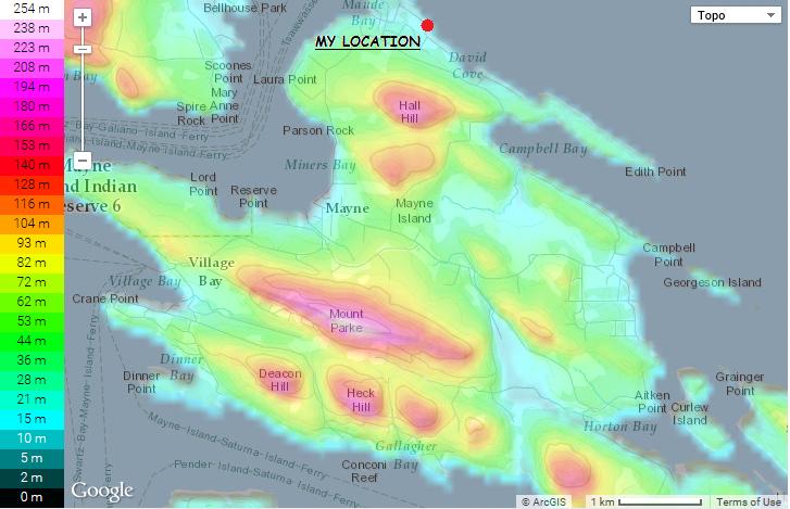 |
| courtesy: http://en-ph.topographic-map.com/ |
Steve McDonald, VE7SL, is a regular contributor to AmateurRadio.com and writes from British Columbia, Canada. Contact him at [email protected].
Amateur Radio Weekly – Issue 74

$8,000 fine proposed for Ham causing interference, failing to identify
Ham volunteered to track down the interference he was causing.
ARRL
Are Amateur Radio-based emergency communications still relevant?
From “we are the be all and end all of disaster communications planning” down to “hams who show up to emergency scenes should be arrested.” So what’s the answer?
VA3QR
Slim Jim vs. Traditional J-pole Antenna
Real measurements of a Slim Jim antenna and traditional j-pole antenna reveal the truth about their respective gain and pattern.
hamradio.me
New, fast JT9 Meteor Scatter modes
Joe Taylor K1JT has published some information about the new ‘Fast JT9’ submodes for Meteor Scatter communication on 28 and 50 MHz.
Southgate
Rufus Turner: Ham Radio’s first African American Operator
Rufus was an engineer who developed the 1N34A germanium diode in the 1946.
KC4LMD
First Tracksoar test flight
The Tracksoar APRS tracker is designed to be flown under anything capable of lifting 60 grams, including balloons, RC planes, quad copters, or anything else that flies.
Tracksoar
Danish CubeSats head for ISS
The IARU have coordinated 437.250 MHz for the 1k2-9k6 bps beacon and 437.425 MHz for the GMSK beacon.
AMSAT UK
SkookumLogger contest logger for OS X
Supporting CW and SSB events on the six HF contest bands plus 6m, 4m, 2m, and 70cm.
K1GQ
CJU satellite antenna for HTs
A minimalist satellite system.
VE6AB
How to
Setting up Ubuntu for Decoding NOAA and Meteor M2 Sats
In this guide, I will attempt to make it easy to set up Ubuntu with GQRX, GNU Radio Companion, WxtoIMG, and Tools for decoding Meteor M2 Sats.
voiceoverman
And finally…
One acorn too many
Woodpecker fills Antenna with Acorns.
YouTube
Amateur Radio Weekly is curated by Cale Mooth K4HCK. Sign up free to receive ham radio's most relevant news, projects, technology and events by e-mail each week at http://www.hamweekly.com.
I’m back…

Mike Weir, VE9KK, is a regular contributor to AmateurRadio.com and writes from New Brunswick, Canada. Contact him at [email protected].
Amateur Radio Newsline Report 1973 August 21, 2015
- BREAKING NEWS
- FILTERD OUT FOREVER
- A HEALTHY DOSE OF HAM RADIO
- WAITING ROOM
- FIELD DAY WITH A TWIST
- SCHOOL'S OUT - SCHOOL'S BACK IN
- HUNTSVILLE HAMFEST YHOTY
- A SHINING BEACON
- THE POLITICS OF RADIO
- DX UP FRONT
- THE WORLD OF DX
- A NATON UNTO ITSELF
AmateurLogic 81: Huntsville with Peter
AmateurLogic.TV Episode 81 is now available for download.
George and Tommy finally meet Peter in person at Huntsville Hamfest!
1:12:40
George Thomas, W5JDX, is co-host of AmateurLogic.TV, an original amateur radio video program hosted by George Thomas (W5JDX), Tommy Martin (N5ZNO), Peter Berrett (VK3PB), and Emile Diodene (KE5QKR). Contact him at [email protected].
 Ham Radio Deluxe |
 W5SWL Electronics |
 Ham Radio Prep |
 KB3IFH QSL Cards  Hip Ham Shirts  HamRadioAuctions HamRadioAuctions Reliance Antennas Reliance Antennas Enigma Shop Enigma Shop |  morseDX  Ni4L Antennas  R&L Electronics R&L Electronics antennas.us antennas.us QRV QRV |
- Matt W1MST, Managing Editor
