 |
 New Satellite (Fox-1A/ AO-85) is Operational
 Congratulations to AMSAT for the successful launch and initial deployment of the Fox-1A amateur radio satellite.This bird has been designated AO-85 and has an FM transponder on board (435.180 MHz uplink, 145.980 MHz downlink).
I have not heard or worked this satellite yet but early reports indicate that it has a strong signal on the downlink. So start out by trying to hear the bird on 145.980 MHz. To find out when it will be overhead, use the AMSAT pass prediction page or your favorite satellite tracking software.
Download the Special Issue of the AMSAT Journal to get the full story.
73, Bob K0NR
The post New Satellite (Fox-1A/ AO-85) is Operational appeared first on The KØNR Radio Site.
Bob Witte, KØNR, is a regular contributor to AmateurRadio.com and writes from Colorado, USA. Contact him at [email protected].
» Leave a Comment (0)
Amateur Radio Newsline Report 1980 October 9, 2015
- WATCHING THE WEATHER
- WEBSITE WOES
- SCOUTS TAKE TO THE AIR
- HAMVENTION INTERVENTION
- PARTYING, NEW YORK STYLE
- ROLL CALL FOR MILITARY CONVOY
- LICENSE NUMBERS ARE DOWN, DOWN UNDER
- THE WORLD OF DX
- SOME KIND OF SUMMIT
» Leave a Comment (0)
They ARE attempting a comeback, after all.
I'm sure many of you got the same email from Heathkit, either yesterday or early this morning. I had to admit that I thought it was going to be another one of those "We're still coming back!" emails, but this one had some substance.
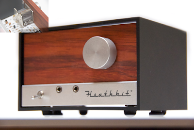
It looks like the initial offerings are a table AM radio as well as some parts for already existing Heathkit products, namely the HW8, as well as their weather instruments.
Everything can be found here: https://shop.heathkit.com/shop
Obviously, it's a small fledgling offering, but every journey of 1,000 miles begins with a single step. So before we make any harsh judgments, let's all take a deep breath, wish the new "Heathkit" well, and see how this all shakes out.
72 de Larry W2LJ
QRP - When you care to send the very least !
Larry Makoski, W2LJ, is a regular contributor to AmateurRadio.com and writes from New Jersey, USA. Contact him at [email protected].
» Leave a Comment (8)
Clear Air Scatter Tests On 458THz
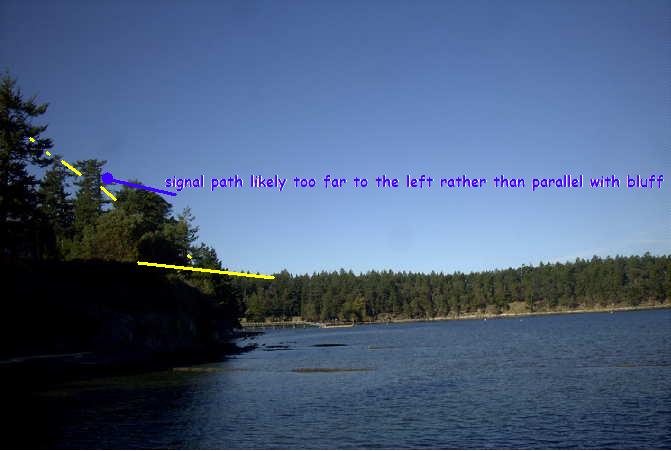
 After patiently waiting for the bright moon to clear the early evening skies, I was finally able to venture out for my first clear-air scatter test this past Sunday night. I had plotted the path on my Mayne Island map and determined bearings as best I could, but the path was going to be very tight. If the path plan was right, my signal should just clear the high beachfront bluffs at the chosen sea-level receiving site.
After carefully aiming the light, I set off for the receive site at around 7:45PM and was all set up with the new lightwave receiver about 30 minutes later. The site appeared fairly quiet and the Argo screen confirmed that there was little QRN coming from the local houses up on the bluff. I listened for over an hour, trying various slow changes in pointing ... varying the azimuth a few degrees at a time, and then the elevation. Unfortunately not the slightest indication of my ~549Hz tone was seen. I was confident that the system was working as several strobes were heard from distant aircraft (near Vancouver), as their flashing lamps skimmed the edge of the far treeline.

It seems likely that either my aiming or bearing calculations (or both) were off and that the signal was probably slightly to the west of me, with the bluff blocking any hope of reception ... I knew it was going to be close but was hoping for a little luck.
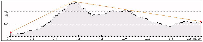
I left the transmitter outside overnight (it was set up two properties to the SE) and decided to try a second shot on Monday night. This path, although shorter by a mile, would require the signal to pass over two high hills ... the first topping out at 667' and the second at 567'. The overall direct-path distance was 1.7 miles (2.7 km). A cross-section of the signal path is shown below as it hugged the edges a little lower than the peaks:
 |
| courtesy: http://www.heywhatsthat.com/profiler.html |
I have been using a 'compass' app on my I-Pad to determine directions when aligning the transmitter and receiver setups. I'm not 100% convinced of its accuracy at all times, as readings can sometimes be a bit flaky. Before doing any more testing, I'll need to solve this, either with a better app or with a real compass.
The transmitter was set up just before darkness, pointing right at the edge of the treeline along the 667' ridge and elevated at a 28 degree takeoff angle. The deep-red, 640mw LED, was switched-on just before departure at around 8:30PM.

It didn't take long to get set up in the back of the CRV, with the receiver temporarily set in no particular direction and plugged into the computer.
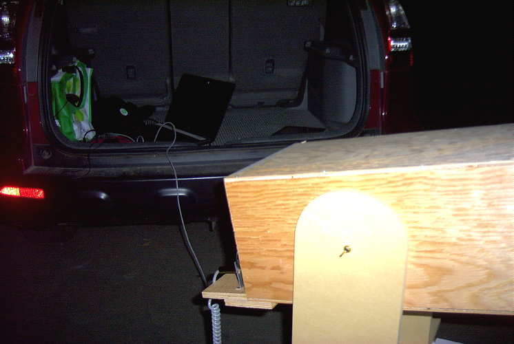
When Argo came to life, I went to the front of the car to grab the I-Pad so that the receiver could be aligned but was surprised to see a bright line at 549Hz when I came back! It seems that my 'rough' placement of the receiver was spot-on, and not exactly where I had originally intended. In fact, there appeared to be about a 10 degree error in where I had planned to point. I later traced the error to my path drawn on the paper map as it was difficult to determine my exact receiving location on the older map, which didn't show the new road where I had set up on.
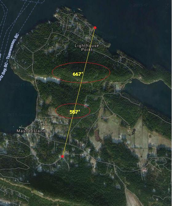 |
| Monday night's path |
With the strength of signals recovered on this path, two-way communication could have easily been established on any of the CW QRSS modes ... if quieter, probably on normal audible CW. Signal strength indicated that there was still plenty 'left in the bucket' for greater distance paths, probably much further than I am able to test here on the island.
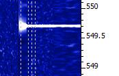
This was the first thing I saw, at the QRSS60 mode in Argo ... a fairly narrow passband and a ~25+ db dig into the noise.
Backing off to a wider bandpass (less sensitive) but faster QRSS10 mode showed the signal still very apparent:

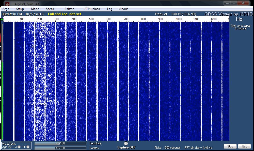
The almost 'real time' QRSS3 mode, although showing a much weaker signal, indicated that the signal would have been almost audible had it not been for the high level of background noise at this site. Don't confuse the lightwave signal with the much stronger 9th harmonic of 60Hz on 540Hz!
The ferry terminal was just down the hill about 1/2 mile and with several kilowatts of spectrum-polluting 60Hz sodium vapor lighting, the cloudy skies were a sea of bright-pink. There was a high level of audible hum in the phones, right from the start, that unfortunately, masked any hope of an audible detection. The waterfall screen capture shown below, illustrates the massive QRM at this otherwise nice site!
The night was not going to be complete without a strobe signature, captured on Argo from a high passing jet aircraft:
 | |
| strobes |
All-in-all, it was a very successful outing, considering the obstructed path and the $5 fresnel lens used in the portable receiver! I've examined the island map for any other possibilities and there are not many suitable candidates. I had hoped for one other possibility towards the west, which would stretch the path by almost another mile, but I'm not really sure that I can get a clear shot without hitting the very close treeline at this end.
I think the next round of testing will be in the other direction ... across Georgia Strait, with John, VE7BDQ, who has expressed interest in doing some deep overnight Argo searches for my signal in the clouds.
I'm not sure which mode would offer the best chance ... 'clear air scatter' or 'cloudbounce'. John has a very good receiver, with a slightly larger and better-quality fresnel than the one used in these tests. Working from his suburban backyard, directly across the strait at 13 miles (21 km) distant, his direct path to me is somewhat obstructed and will require an elevation angle of around 30 degrees at his end. I think, ideally, we would both like to be skimming just above the ocean, with only a slight elevation. A lower and less obstructed shot from his yard would mean an oblique path so this also remains a possibility. We will play with what we have and hope for the best ... even just a trace of signal would be a measured success.
I think that a non-line-of-sight (NLOS) contact would make an exciting challenge and a great project for two amateurs living in the same city or town, and ... you really don't even need a ticket!
For more technical details on the equipment used in this test, see "A West Coast Lightwave Project" describing the activities between here and Markus, VE7CA. We have just learned that this article will be published in the 2016 Radio Amateur's Handbook ... hopefully inspiring more new lightwave activity!
Steve McDonald, VE7SL, is a regular contributor to AmateurRadio.com and writes from British Columbia, Canada. Contact him at [email protected].
» Leave a Comment (1)
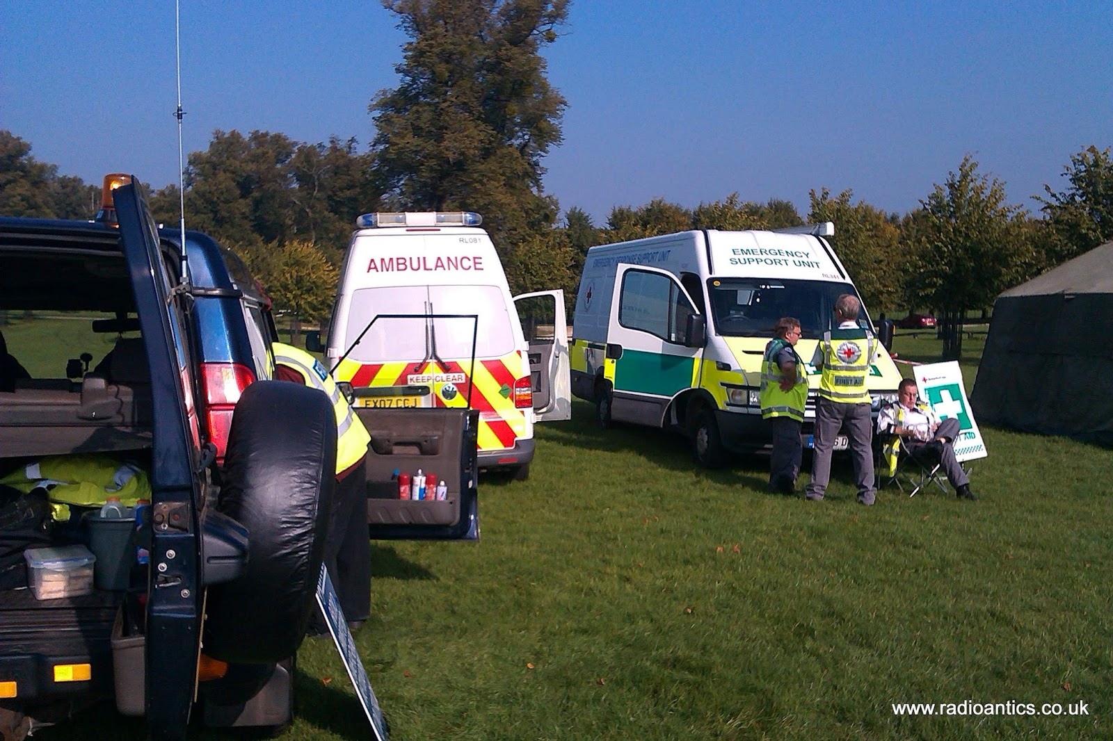
My first RAYNET event
Sunday I took part in my first RAYNET event at the Walk for Parkinson's at Burghley House in Lincolnshire. This was a sponsored walk to raise money for Parkinson's UK a research and support charity working to help find a cure and improve life for those affected by Parkinson’s disease.
Starting at the Burghley House stately home, participants could chose to do either a gentle 3 mile stroll within the grounds or a more challenging 10-mile walk out of the park and through the Barnack Hills and Holes National Nature Reserve.
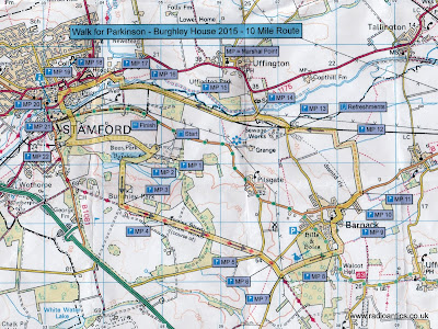
RAYNET's task was to provide communication support to the organisers with operators situated around the course at various marshalling points to pass messages and if necessary request assistance.
Earlier in the year there was a presentation about the work of RAYNET at the South Kesteven ARS by Jim Wheeldon (M0JHW) and Alan Clarke (M0NLR) after which I'd offered my services for future events, so when Jim called me and asked for some help I was happy to oblige.
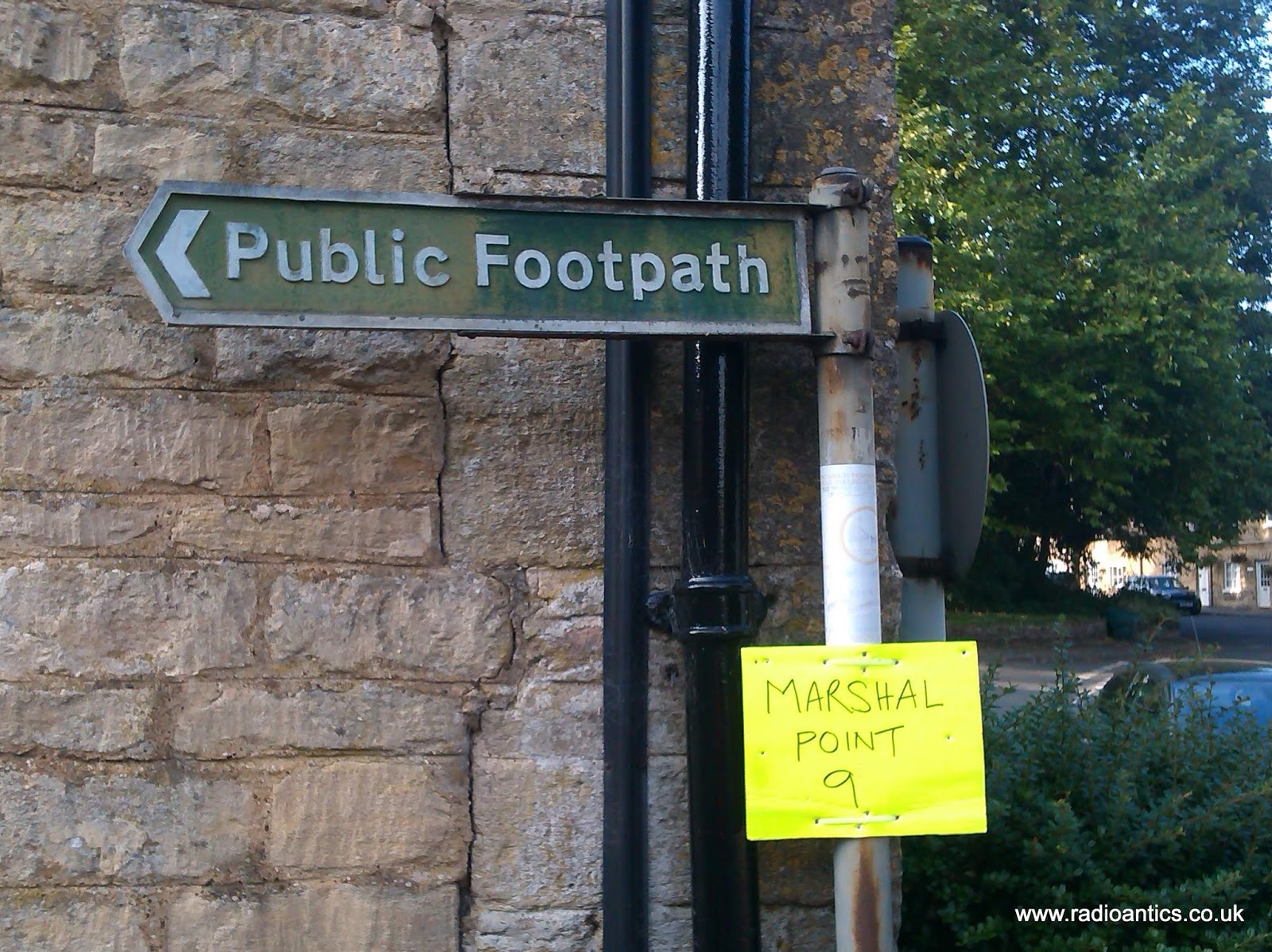
My task was quite straightforward, simply manning one of the marshal points along the course directing the walkers and making sure they were happy and injury free, if not I was to call for assistance. Despite being under the weather for the last few days with a bad head cold and a painful sore throat I still turned out and really enjoyed helping.
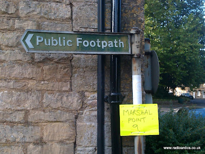
It was nice to use my radio licence and equipment for something useful, spending a pleasant morning in the sunshine talking to the walkers and some local residents explaining all about amateur radio.

RAYNET was formed back in the 1950s following the East Coast floods to provide a way of organising the valuable resource that Amateur Radio is able to provide to the community. While it is called the Radio Amateurs’ Emergency Network the majority of its work nowadays is to provide support to community events, like the sponsored walk.
However it can still be called up to offer assistance at incidents such as the recent Shoreham Airshow plane crash. The South Sussex RAYNET group, assisted by members of South Kent RAYNET, were already providing communications support for the organisers and the user services at the airshow when the Hawker Hunter aircraft crashed into vehicles on the A27 during a flying display.
It was reported that following the crash the area was in lock down in four hours and it the demand on the local mobile networks by concerned spectators, residents and residents outstripped capacity making normal communication difficult. RAYNET operators were able to provide much needed support in the aftermath.
Andrew Garratt, MØNRD, is a regular contributor to AmateurRadio.com and writes from East Midlands, England. Contact him at [email protected].
Starting at the Burghley House stately home, participants could chose to do either a gentle 3 mile stroll within the grounds or a more challenging 10-mile walk out of the park and through the Barnack Hills and Holes National Nature Reserve.

RAYNET's task was to provide communication support to the organisers with operators situated around the course at various marshalling points to pass messages and if necessary request assistance.
Earlier in the year there was a presentation about the work of RAYNET at the South Kesteven ARS by Jim Wheeldon (M0JHW) and Alan Clarke (M0NLR) after which I'd offered my services for future events, so when Jim called me and asked for some help I was happy to oblige.
My task was quite straightforward, simply manning one of the marshal points along the course directing the walkers and making sure they were happy and injury free, if not I was to call for assistance. Despite being under the weather for the last few days with a bad head cold and a painful sore throat I still turned out and really enjoyed helping.
It was nice to use my radio licence and equipment for something useful, spending a pleasant morning in the sunshine talking to the walkers and some local residents explaining all about amateur radio.
RAYNET was formed back in the 1950s following the East Coast floods to provide a way of organising the valuable resource that Amateur Radio is able to provide to the community. While it is called the Radio Amateurs’ Emergency Network the majority of its work nowadays is to provide support to community events, like the sponsored walk.
However it can still be called up to offer assistance at incidents such as the recent Shoreham Airshow plane crash. The South Sussex RAYNET group, assisted by members of South Kent RAYNET, were already providing communications support for the organisers and the user services at the airshow when the Hawker Hunter aircraft crashed into vehicles on the A27 during a flying display.
It was reported that following the crash the area was in lock down in four hours and it the demand on the local mobile networks by concerned spectators, residents and residents outstripped capacity making normal communication difficult. RAYNET operators were able to provide much needed support in the aftermath.
Andrew Garratt, MØNRD, is a regular contributor to AmateurRadio.com and writes from East Midlands, England. Contact him at [email protected].
» Leave a Comment (0)
My first RAYNET event
Sunday I took part in my first RAYNET event at the Walk for Parkinson's at Burghley House in Lincolnshire. This was a sponsored walk to raise money for Parkinson's UK a research and support charity working to help find a cure and improve life for those affected by Parkinson’s disease.
Starting at the Burghley House stately home, participants could chose to do either a gentle 3 mile stroll within the grounds or a more challenging 10-mile walk out of the park and through the Barnack Hills and Holes National Nature Reserve.
RAYNET's task was to provide communication support to the organisers with operators situated around the course at various marshalling points to pass messages and if necessary request assistance.
Earlier in the year there was a presentation about the work of RAYNET at the South Kesteven ARS by Jim Wheeldon (M0JHW) and Alan Clarke (M0NLR) after which I'd offered my services for future events, so when Jim called me and asked for some help I was happy to oblige.
My task was quite straightforward, simply manning one of the marshal points along the course directing the walkers and making sure they were happy and injury free, if not I was to call for assistance. Despite being under the weather for the last few days with a bad head cold and a painful sore throat I still turned out and really enjoyed helping.
It was nice to use my radio licence and equipment for something useful, spending a pleasant morning in the sunshine talking to the walkers and some local residents explaining all about amateur radio.
RAYNET was formed back in the 1950s following the East Coast floods to provide a way of organising the valuable resource that Amateur Radio is able to provide to the community. While it is called the Radio Amateurs’ Emergency Network the majority of its work nowadays is to provide support to community events, like the sponsored walk.
However it can still be called up to offer assistance at incidents such as the recent Shoreham Airshow plane crash. The South Sussex RAYNET group, assisted by members of South Kent RAYNET, were already providing communications support for the organisers and the user services at the airshow when the Hawker Hunter aircraft crashed into vehicles on the A27 during a flying display.
It was reported that following the crash the area was in lock down in four hours and it the demand on the local mobile networks by concerned spectators, residents and residents outstripped capacity making normal communication difficult. RAYNET operators were able to provide much needed support in the aftermath.
Andrew Garratt, MØNRD, is a regular contributor to AmateurRadio.com and writes from East Midlands, England. Contact him at [email protected].
» Leave a Comment (0)
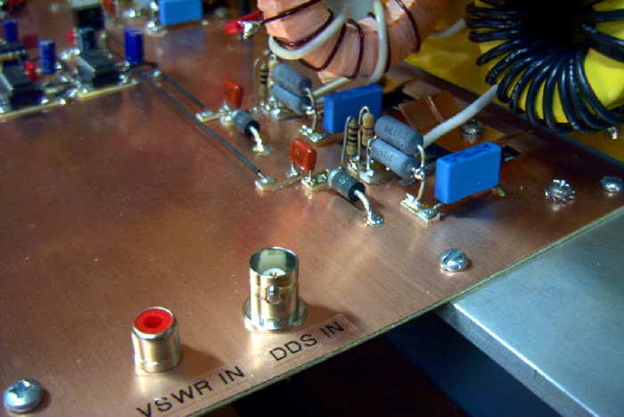
More Manhattan Building Tips
 |
| 2200m kW Transmitter |
One of my early blogs described how I make the pads needed for Manhattan style. It can pretty much be used for any modern project and has been used here for countless circuits ... from a 1W LF tranmsitter to my 2200m/630m kilowatt.
 |
| 1W LF Transmitter |
I found these hints from Bob about pads and soldering components particularly helpful for anyone making a start in Manhattan style building:
Round pads require only placing in proper X and Y coordinates. A rectangular or square pad also requires proper rotation. A rectangular pad placed cockeyed doesn't look good.
I've had good luck with pads made from .032 double sided board. Solder surface tension prevents shorts with this pad thickness. My experiments making pads from thinner .010 thick flexible board often resulted in shorts.
A clean surface is needed for good pad adhesion to the board. I polish the pad board on both sides to a shine and then punch out the pads.
Pads can take up a lot of solder so I prefer to use 1/8th inch (.125) diameter pads.
Some of my Manhattan projects have failed because pads have loosened from the board. Cheap, discount super glue was my mistake. I now use Loctite Super Glue Gel. Of the hundreds of pads I've applied, I've never had one loosen.
If a punch is used to make pads each pad will have a rounded side and concave side. My pads are applied rounded side up. Using tweezers, I pick up a pad, place a small dab of glue on the punch mark and drop the pad in place. Light tweezer pressure is used to set the pad. Too much pressure squeezes out the glue leaving a weak joint. I Use enough glue so it squeezes out around the bottom edge of the pad.
Disaster occurs if glue gets on the tweezers. Pads stick to tweezers and won't stick to the board. If this happens, I stop and wipe off the tweezers with a cloth. I also use an Exacto knife to remove any hardened glue on the tweezer tips.
I try not to put too many leads to a pad. For example, its common for a transistor base lead to connect to two resistors and two capacitors. If this happens I extend the transistor base lead across two adjacent pads ans share the connections between the two pads.
I take time to shape my component leads. I make certain I don't have to flex a lead, like a spring, to solder it in place. Improper technique means the next component soldered to the pad may spring loose the earlier lead.
I put a bend in the component lead so the lead sets level on the pad. But the bend doesn't need to be long. A bend a 1/16th inch long, or half the diameter of the pad works well. This also means multiple leads can attach to a pad, each pointing toward the pad center.
My Hakko 936 soldering station is rated for 50 watts. I use a wide tip to get that power to the pads. I'm surprised how much power is required to do Manhattan construction. This is especially true when soldering component ground leads to the project board.
It is very easy to come away with cold solder joints. After all the leads are attached to a pad I Heat all the solder on the pad to liquid state. My ground connections take 1-2 seconds and pad connections take about 1 second. I've had no damage to components due to the heat I apply.
I prefer to use .032 leaded solder for my pad connections. But I use .062 solder for ground connections or to fill in a heavily populated pad.
I offer these ideas for what they are worth to you.
bob-N7SUR
Bob also mentioned that he prefers to tape down a full size plan of his component layout as an aid in placing his pads ... a light punch mark through the paper layout, marking the pad's location. I haven't gone this far with any of mine, preferring to place pads as I build, giving flexibility to component placement.
There are lots of good online references for Manhattan-style building but be warned ... some of them, particularly the pages of Dave, AA7EE, will have you making plans and reaching for the soldering iron before you know what's happened!
Steve McDonald, VE7SL, is a regular contributor to AmateurRadio.com and writes from British Columbia, Canada. Contact him at [email protected].
» Leave a Comment (3)
Please support our generous sponsors who make AmateurRadio.com possible:
 Ham Radio Deluxe |
 W5SWL Electronics |
 Ham Radio Prep |
 KB3IFH QSL Cards  Hip Ham Shirts  HamRadioAuctions HamRadioAuctions Reliance Antennas Reliance Antennas Enigma Shop Enigma Shop |  morseDX  Ni4L Antennas  R&L Electronics R&L Electronics antennas.us antennas.us QRV QRV |
- Matt W1MST, Managing Editor
