 |
 Weekly Propagation Summary – 2016 Jan 18 16:10 UTC
Here is this week’s space weather and geophysical report, issued 2016 Jan 18 0131 UTC.
Highlights of Solar and Geomagnetic Activity 11 – 17 January 2016
Solar activity ranged from very low to low levels. Very low conditions were observed on 11-14 January and again on 16-17 January. Low levels occurred on 15 January with a few weak C-class flares observed from Region 2480 (N02, L=125, class/area Eso/190 on 10 Jan). A 14 degree long filament, centered near S30W03, erupted between 14/1803-2048 UTC. An associated coronal mass ejection (CME) was visible in SOHO LASCO imagery beginning at 14/2324 UTC. Analysis, and subsequent WSA-Enlil model output, determined a potential glancing blow could impact Earth early on 19 Jan.
No proton events were observed at geosynchronous orbit.
The greater than 2 MeV electron flux at geosynchronous orbit was at high levels throughout the summary period.
Geomagnetic field activity began the period on 11-14 January at quiet to active levels due to effects from a negative polarity coronal hole high speed stream (CH HSS). Quiet conditions persisted on 15-17 January. ACE satellite parameters indicated a maximum wind speed reading of 662 km/s at 12/0711 UTC. By period's end, wind speeds had declined to about 330 km/s. Total field (Bt) reached a maximum reading of 10 nT late on the 10th and generally ranged between 3-7 nT for a majority of the period. The Bz component varied between +/- 7 nT from late on the 11th through early on the 13th. Through the remainder of the period, Bz did not vary much beyond +/- 4 nT. The phi angle was in a predominately negative (towards) orientation through midday on 16 January when a rotation to a more positive (away) sector was observed.
Forecast of Solar and Geomagnetic Activity 18 January – 13 February 2016
Solar activity is expected to be at very low levels with a chance for C-class flares throughout the outlook period.
No proton events are expected at geosynchronous orbit.
The greater than 2 MeV electron flux at geosynchronous orbit is expected to be at high levels on 18, 23-26, 29-31 January, 01-06 and 09-13 February. Normal to moderate levels are expected for the remainder of the outlook period.
Geomagnetic field activity is expected to be at unsettled to active periods on 18-19 January due to possible glancing blow effects from the 14 Jan CME. Unsettled to active levels are expected on 22-23, 28-29 January, 02-03 and 07-09 February due to recurrent CH HSS effects. Predominately quiet levels are expected for the remainder of the outlook period.
Don’t forget to visit our live space weather and radio propagation web site, at: http://SunSpotWatch.com/
Live Aurora mapping is at http://aurora.sunspotwatch.com/
If you are on Twitter, please follow these two users: + https://Twitter.com/NW7US + https://Twitter.com/hfradiospacewx
Get the space weather and radio propagation self-study course, today. Visit http://nw7us.us/swc for the latest sale and for more information!
Check out the stunning view of our Sun in action, as seen during the last five years with the Solar Dynamics Observatory (SDO): https://www.youtube.com/watch?v=zXN-MdoGM9g
We’re on Facebook: http://NW7US.us/swhfr
Visit, subscribe: NW7US Radio Communications and Propagation YouTube Channel
Yaesu, where is the FT-817’s successor?
As a proud owner of Yaesu gear going right back to an FT7 in 1979, I wish them well. In recent times, life has been very hard for them, and they seemed to lose their way. Today, they still face a threat from China and many of their radios are struggling to compete on price. I was totally amazed at their stupidity at not bringing an FT817 successor to market as we approached the solar peak.
It is rumoured that an FT817 successor will be announced at Dayton in May this year. Like many around the world, I hope they do. There is (was?) a vast market for this product as the original FT817 is now very very old. To do a successor would be so easy. Yaesu – get real and release this product before you lose the market. To not put too fine a point on this, I think if you do not, then you risk bankruptcy within 5 years.
My recommendations to Yaesu are:
1. Design in Japan but make in China (but with excellent quality control in place from the start).
2. Launch a successor to the FT817 soon.
3. Look at your product range and rationalise it.
You must survive. This is the real world.
Roger Lapthorn, G3XBM, is a regular contributor to AmateurRadio.com and writes from Cambridge, England.
LHS Episode #160: Tipsy Cow Tipping
 Welcome to Episode #160 of Linux in the Ham Shack. In this episode, minus one VE2XPL, your hosts discuss amateur radio scholarships, the demise of a legendary kit maker, several Linux tutorial sites, a new web-based SDR resource, WSPR, a logger for Android and much, much more. Thanks for listening, and Happy New Year!
73 de The LHS Crew
Russ Woodman, K5TUX, co-hosts the Linux in the Ham Shack podcast which is available for download in both MP3 and OGG audio format. Contact him at [email protected].
Get a taste of the RF coming and going
Elecraft CP1 - A tasty RF treat
 |
| Elecraft CP1 Kit |
Couple what?
Ah, so if your new to this like me you might be asking what does a coupler do? Well it sorta listens in on the signal going out (forward) and reflected (back) and is able to send an attenuated sample of the signal to other devices. It attenuates the sample by either 20db or 30db depending on how you build the kit.The 20db version is good for signals 25 watts and less so that's the way I built it. It was easy to build but my glue under the second toroid wasn't strong enough and you can see it popped up a bit. Also the Elecraft instructions had one confusing instruction concerning mounting the toroids. The instructions say "... When wound and mounted correctly, the enamel wire will emerge from the top of each core and connect to the top hole at each inductor location". Well when you wind a toroid only one of the wires can "emerge from the top of the core" while the other comes from underneath. This confused me for a minute until I finally just went on with the install. Anyway, if you're a stickler for following instructions that one may cause a moment of pause...
The switches for the two outputs forward, reflected (J3, J4) are in the up position when they are not in use. When the switch(es) are in the up position the 50 ohm 3 watt resistor(s) take the place of the switched off output. Don't disconnect an output and leave the switch in the bottom position. I'm not sure what will happen... maybe nothing, probably a bit of a mismatch on the SWR, or maybe it could be like "Crossing the streams" in Ghostbusters. Your mileage may vary.
My uses for a coupler
My old Ten-Tec Century 21 has an analog VFO dial that gives me a good guess at where I'm at but I use an external frequency counter to give me more information. I had it sorta rigged my frequency counter to sample the signal from RF leaked on the shield but I didn't really know how much power I was sending to the counter so this coupler allows it, as well as other devices, to be safely connected to the transmitted signal.I also plan to use the coupler for IMD tests using a oscilloscope and other projects. It's handy device to have in your collection.
My confusion
But in the end - It works
Richard Carpenter, AA4OO, is a regular contributor to AmateurRadio.com and writes from North Carolina, USA. Contact him at [email protected].
An afternoon with JT-65HF
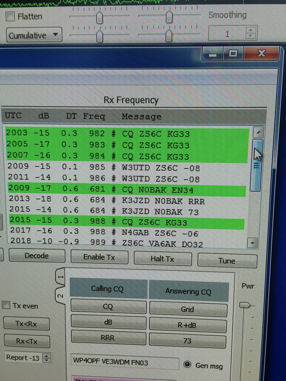
Mike Weir, VE9KK, is a regular contributor to AmateurRadio.com and writes from New Brunswick, Canada. Contact him at [email protected].
SOTA Rig Reconfiguration
Since I've retired, I've now have the opportunity to have continuous thoughts about things like this without the interference of work or schedule related thoughts, it's great. Consequently, I've had some time to give my rig configuration some thought. What I have done is not totally unique as I have gotten ideas from others and mixed them into my own concoction. I have the 3 Band MTR, with 17m, 20m and 30m. I chose these particular bands so that I would have flexibility on contest weekends. So below is my latest, not my last configuration.
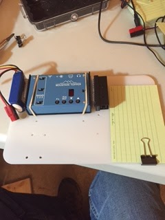
As you can see I am using a backpacking cutting board as the foundation of the setup. I used a product called Scotch Extreme fastener to attache the LIPO battery and the Pico Paddle, it's sort of like Velcro but it snaps into place and is 10x stronger than velcro. I simply drilled holes (this board has seen several iterations as you can see the many holes), and used rubber bands to hold the radio in place. I may decide to use the fastener instead. The "Rite in the Rain" card is for logging. A nice neat package to pull out of the pack, hook up the antenna, plug in the power and off I go.
There are however a couple of further improvements.
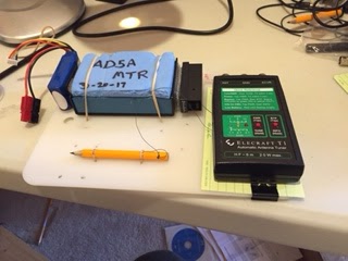
You can see I've added a tethered pencil for logging and an optional Elecraft T1 tuner, if you have a non-resonant wire. I can fasten it to the board with either rubber bands or the Scotch fastener.
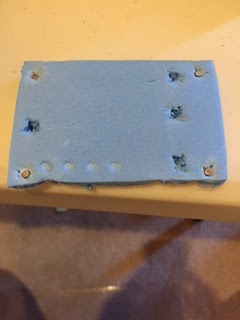
I've also added a protective cover for the MTR. It's made from sleeping pad foam and protects the face and switches on the MTR when getting jostled in your pack. On the backside of the cover I've cut out recesses where the switches are and added little magnets that are attracted to the four screws on the case. Thanks to Fred, KT5X for this idea.
So there you have it, a light, three band, package that is compact, light and ready to go. So until I reconfigure again.
Mike Crownover, AD5A, is a regular contributor to AmateurRadio.com and writes from Texas, USA. Contact him at [email protected].
SOTA Rig Reconfiguration
Since I've retired, I've now have the opportunity to have continuous thoughts about things like this without the interference of work or schedule related thoughts, it's great. Consequently, I've had some time to give my rig configuration some thought. What I have done is not totally unique as I have gotten ideas from others and mixed them into my own concoction. I have the 3 Band MTR, with 17m, 20m and 30m. I chose these particular bands so that I would have flexibility on contest weekends. So below is my latest, not my last configuration.
As you can see I am using a backpacking cutting board as the foundation of the setup. I used a product called Scotch Extreme fastener to attache the LIPO battery and the Pico Paddle, it's sort of like Velcro but it snaps into place and is 10x stronger than velcro. I simply drilled holes (this board has seen several iterations as you can see the many holes), and used rubber bands to hold the radio in place. I may decide to use the fastener instead. The "Rite in the Rain" card is for logging. A nice neat package to pull out of the pack, hook up the antenna, plug in the power and off I go.
There are however a couple of further improvements.
You can see I've added a tethered pencil for logging and an optional Elecraft T1 tuner, if you have a non-resonant wire. I can fasten it to the board with either rubber bands or the Scotch fastener.
I've also added a protective cover for the MTR. It's made from sleeping pad foam and protects the face and switches on the MTR when getting jostled in your pack. On the backside of the cover I've cut out recesses where the switches are and added little magnets that are attracted to the four screws on the case. Thanks to Fred, KT5X for this idea.
So there you have it, a light, three band, package that is compact, light and ready to go. So until I reconfigure again.
Mike Crownover, AD5A, is a regular contributor to AmateurRadio.com and writes from Texas, USA. Contact him at [email protected].
 Ham Radio Deluxe |
 W5SWL Electronics |
 Ham Radio Prep |
 KB3IFH QSL Cards  Hip Ham Shirts  HamRadioAuctions HamRadioAuctions Reliance Antennas Reliance Antennas Enigma Shop Enigma Shop |  morseDX  Ni4L Antennas  R&L Electronics R&L Electronics antennas.us antennas.us QRV QRV |
- Matt W1MST, Managing Editor
