 |
 CQ 160m CW Weekend
This past weekend's CQ 160m CW Contest saw the normally quiet band bursting to life with signals stacked up, one atop the other, from 1800 -1870 kHz.
At times it was very difficult to find a clear frequency to send 'CQ' and much of the contest was spent in the 'search and pounce' (S&P) mode. When a clear frequency was found I was able to have several short runs but running for any length of time while in the low power category is not realistic. I think my best hourly rate peaked at '60' for a short time as propagation would improve momentarily ... often, ten or more CQ's would go unanswered and then the next one would have two or three responses, continuing on for several minutes until the propagation would shift. These sudden 'holes' in the D-layer absorption seem to occur when conditions are marginal and it's as if the propagation switch is suddenly thrown from 'poor' to 'really good' for a few short minutes.
Overall, conditions from western B.C. were poor on Friday night and much improved on Saturday night. Although several DX stations were heard and called on Friday night, none were worked. These same stations came right back when called, on Saturday evening.
My 160m antenna is very simple, consisting of a 'half-sloper' and about fifty in-ground radials. Since the tower and antenna are mounted right at the ocean's edge, this year I threw two extra radials into the ocean ... whether or not these made any difference is difficult to say but they certainly wouldn't make things worse.

Because of the proximity to the ocean and the half-sloper producing vertical polarization, my antenna always seems to favor stations at the ends of the single-hop F2 distance ... those along the east coast and into the Caribbean as opposed to mid-continent signals. I often find myself sending several repeats to stations in the central states while those on the far coast will reply on the first call ... even stations that I can barely copy, will often come right back, which seems puzzling.
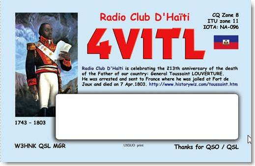
Overall, about 10 hours were spent in the contest ... ending up with 223 contacts in 51 sections and 9 DX entities. Some of the DX stations worked were PJ2, HK1, ZF2, C6, KP2 and 4V1. Checking my 160m DXCC list after the contest, I was surprised to see that 4V1TL in Haiti was a new country for me, making the contest time well worth it. Claimed scores for this, and any contest, can be viewed on the 3830 Scores website.
As the solar cycle continues to decline, 160m conditions should only get better and better, with the next few years hopefully producing a few Europeans in the 160m log once again.
Steve McDonald, VE7SL, is a regular contributor to AmateurRadio.com and writes from British Columbia, Canada. Contact him at [email protected].
HamRadioNow: 60 Meters… Let’s Go Dutch
I’ll coin a phrase for a program like this: Wonkie-Talkie.
The WRC (World Radio Conference) last November ended up with a worldwide Amateur Radio 60 Meter allocation of 15 kHz. You’ll be forgiven if you thought there already was a 60 meter allocation, as many countries have authorized 60 Meter Amateur operation. But it’s never been a formal ITU deal.
But 15 kHz, with a power restriction of about 10 watts into a dipole? (Or 15 watts EIRP – an ‘isotropic radiator’ – a dipole has 2 dB gain over an isotropic radiator?) Compared to the 5 discrete SSB/CW/digital channels we have now with a 100 watt/dipole power limit…. is that a win, lose or draw?
In this Episode of HamRadioNow, ARRL Chief Technology Officer Brennan Price N4QX explains how the WRC ended up with this meager offering, and how hams in the US and other countries with maybe more spectrum and certainly more power may continue to enjoy those privileges. Or not… At the very least, the FCC won’t act on the WRC changes for some time… maybe years.
Well, it’s years if we’re gaining something, like the 137 kHz spectrum that was authorized in WRC 07, that we’re just getting rules opening it up to US hams now. But if we’re losing something?
Brennan is happier to talk about some of the defensive successes at WRC 15. If half the battle is gaining spectrum, the other half is avoiding losing it. And there were many eyes on some of our microwave allocations, but the attacks were fended off.
So, Wonkie-Talkie? You’ll also be forgiven if you drift off to work some DX on 20…. while we still have 20….
Oh, and ‘Let’s Go Dutch’? The contingent from the Netherlands strongly supported a wider allocation and 100 watt limit. They compromised down to 100 kHz, but were out-shouted (apparently there is no voting) by the “almost nothing” faction. So their government immediately authorized Dutch hams that 100 kHz/100 watts anyway.
Brennan says it’s not going to happen here in the US.
73, Gary KN4AQ
And if you don’t have time to watch, maybe you have time to listen while you commute or work out (work out? Hams? Who am I kidding?). Paste this into your podcast app: http://HamRadioNow.tv/hrn/hrnrss.xml. You’ll be subscribed to our audio download.
Gary Pearce, KN4AQ, is the host of HamRadioNow.tv. If you enjoy this and other HamRadioNow programs, help keep them 'on the air' with a contribution. Contact him at [email protected].
Weekly Propagation Summary – 2016 Feb 01 16:10 UTC
Here is this week’s space weather and geophysical report, issued 2016 Feb 01 0641 UTC.
Highlights of Solar and Geomagnetic Activity 25 – 31 January 2016
Solar activity was at very low to low levels during the period. Low levels were observed from 25-29 January with Regions 2488 (N02, L=320, class/area Dai/240 on 25 January) and 2489 (N10, L=253, class/area Eko/300 on 29 January) producing the majority of the C-class flaring. The largest flare of the period was a C9/1f at 28/1202 UTC from Region 2488. Region 2488 was in slow decay over the period. Region 2489 continued to exhibit growth through 28 January and slowly decayed thereafter. Several filament eruptions, and subsequent coronal mass ejections (CMEs), were observed during the period, but none had an Earth-directed component.
No proton events were observed at geosynchronous orbit.
The greater than 2 MeV electron flux at geosynchronous orbit was at high levels from 25-27 January, moderate levels on 28 January, and normal levels from 29-31 January. The maximum flux of the period was 2,117 pfu observed at 26/1500 UTC.
Geomagnetic field activity was at mostly quiet levels throughout the period with isolated unsettled periods on 27-28 and 31 January and an isolated active period observed late on 31 January. Solar wind parameters were in decline as the period began under the waning influence of a negative polarity coronal hole high speed stream (CH HSS). Solar wind speed gradually decreased from approximately 480 km/s early in the period to around 260 km/s by 30 January before increasing slightly to 300 km/s by the end-of-the-period. A solar sector boundary crossing into a positive (away) orientation occurred at approximately 27/0834 UTC, accompanied by a slight increase in total field (Bt) measurements to 9 nT on 27 and 28 January. On 31 January, another increase in Bt to 10 nT was observed along with a prolonged period of southward Bz. The geomagnetic field responded with isolated active levels to end the period.
Forecast of Solar and Geomagnetic Activity 01 February – 27 February 2016
Solar activity is expected to be at very low to low levels with a chance for M-class flares (R1-R2, Minor-Moderate) from 03-25 February with the return of old Regions 2484 (N08, L=094) and 2488 (N02, L=320).
No proton events are expected at geosynchronous orbit.
The greater than 2 MeV electron flux at geosynchronous orbit is expected to be at normal to moderate levels with high levels likely on 04-07, 09-15, and 18-23 February as a result of CH HSS influence.
Geomagnetic field activity is expected to be at unsettled to active levels on 01 February due to continued effects from a prolonged period of southward Bz. Unsettled to active levels are likely from 02-04, 08-09, and 17-20 February due to recurrent CH HSS activity.
Don’t forget to visit our live space weather and radio propagation web site, at: http://SunSpotWatch.com/
Live Aurora mapping is at http://aurora.sunspotwatch.com/
If you are on Twitter, please follow these two users: + https://Twitter.com/NW7US + https://Twitter.com/hfradiospacewx
Get the space weather and radio propagation self-study course, today. Visit http://nw7us.us/swc for the latest sale and for more information!
Check out the stunning view of our Sun in action, as seen during the last five years with the Solar Dynamics Observatory (SDO): https://www.youtube.com/watch?v=zXN-MdoGM9g
We’re on Facebook: http://NW7US.us/swhfr
Visit, subscribe: NW7US Radio Communications and Propagation YouTube Channel
Winner announcement: 2016 NooElec Giveaway

First of all, thank you to the 2,015 people from all over the world who entered the giveaway. That’s a record number of entries for us!
Now for the moment you’ve been waiting for… the winners! OK, here they are:

We will contact the winners by e-mail with further instructions today. If you are one of the 41 winners, please reply quickly so that we can get your prize on the way to you! If you don’t receive your e-mail today, please double-check your spam folder to make sure it didn’t end up there.
Here are the prizes:
 One (1)
HackRF One SDR transceiver bundle
Estimated retail value $500 each
Contains everything you need to listen to, and transmit, HF, VHF & UHF (1 MHz to 6 GHz) with the HackRF One from Great Scott Gadgets, down to 100kHz or lower! Standard bundle includes HackRF, Ham It Up, Antenna Balun, 2 SMA interconnect cables and an SMA to BNC adapter. Pre-installed in a black aluminum enclosure and with the RF shield.
 Three (3)
NESDR XTR+ HF bundles
Estimated retail value $140 each
Each kit will contain an SDR, an upconverter to enable HF reception, and a cable to connect the two units.
 Two (2)
NESDR Mini 2+ HF bundles
Estimated retail value $125 each
Each kit will contain an NESDR Mini 2+ SDR with 0.5PPM TCXO, MCX-connected antenna for VHF, an upconverter to enable HF reception, and a cable to connect the two units.
 Ten (10)
NESDR XTR+ sets
Estimated retail value $60 each
NooElec NESDR XTR+ SDR & DVB-T USB set, including GPS-rated +/- 0.5PPM TCXO, quality telescopic antenna and remote control. Genuine Elonics E4000 tuner is guaranteed.
 Ten (10)
NESDR Nano 2+ sets
Estimated retail value $30 each
Same form factor as the Nano 2 but with a TCXO!
 Fifteen (15)
NESDR Nano 2 sets
Estimated retail value $25 each
The NESDR Nano 2 is based on the R820T2 tuner IC made by Rafael Micro, which means an approximate tuning range of 25MHz-1700MHz and improved selectivity and sensitivity in most frequency ranges versus R820T-based SDRs. There is also an RTL2832 (RTL2832U) IC on board of course, to provide basic demodulation and USB interface functionality
a special BIG thank you to NooElec!
Matt Thomas, W1MST, is the managing editor of AmateurRadio.com. Contact him at [email protected].
Arduino DTMF Decoder and Relay Controller
Another Arduino project I’ve been working on is a DTMF decoder used to control a relay board. Using a ham radio receiver, I can switch lights, radios, computers…anything…on or off from miles away. Here’s the video:
Here’s the wiring diagram. And here’s the Arduino code.
I’m using a Sainsmart 4 relay board, although pretty much any relay board would work. You’ll also need a MT8870 DTMF decoder – these run about $2 on ebay. And of course, you’ll need an Arduino Uno. Again, check out ebay for these as well. The total cost here should be less than $12 and you’ve got a fully functioning radio controlled DTMF relay controller!
Michael Brown, KG9DW, is a regular contributor to AmateurRadio.com and writes from Illinois, USA. Contact him at [email protected].
PAØRDT Miniwhip Shakedown

A recent posting to Yahoo's 'NDB List Group' by Mike, an ardent NDB DXer in the UK (Sussex), announced the recent completion of his four-part video series describing the installation and testing of a new PAØRDT active antenna.
If you may be contemplating the installation of an active antenna such as this, or perhaps making a start at DXing the NDB band or listening on 630m, then you might enjoy following Mike's journey as he demonstrates that living in the noisy suburbs need not keep you from enjoying the LF/MF bands. Mike includes some interesting tests involving his grounding system versus noise ingress and the results of keeping the electrical main's ground isolated (or not) from the antenna cable's ground.
The PAØRDT active whip is available from PAØRDT himself or if you are handy with a soldering iron, you might choose to build the same antenna in your workshop. These simple yet highly effective receiving antennas are being used successfully by hundreds of listeners all over the world and for their size provide some pretty amazing performance.
Much more information on the PAØRDT e-probe antenna may be found here in a previous blog posting. To see more of Mike's videos, you can visit his interesting Youtube Channel here.
Steve McDonald, VE7SL, is a regular contributor to AmateurRadio.com and writes from British Columbia, Canada. Contact him at [email protected].
 Ham Radio Deluxe |
 W5SWL Electronics |
 Ham Radio Prep |
 KB3IFH QSL Cards  Hip Ham Shirts  HamRadioAuctions HamRadioAuctions Reliance Antennas Reliance Antennas Enigma Shop Enigma Shop |  morseDX  Ni4L Antennas  R&L Electronics R&L Electronics antennas.us antennas.us QRV QRV |
- Matt W1MST, Managing Editor
