 |
 What’s In Your Rubber Duck?
 Anyone with a VHF or UHF handheld transceiver (HT) probably uses the standard “rubber duck” antenna for casual use. I often refer to the rubber duck as The World’s Most Convenient Crappy Antenna. To be fair, all antennas are a compromise…the rubber duck optimizes small size and convenience at the expense of performance. The Wikipedia entry describes the rubber duck antenna as “an electrically short monopole antenna…[that] consists of a springy wire in the shape of a narrow helix, sealed in a rubber or plastic jacket to protect the antenna.“
Being curious about what really is hiding inside the typical rubber duck antenna, I decided to take a few of them apart. I did not try to assess the performance of the antennas but just examine their construction.
Baofeng UV-5R Stock Antenna
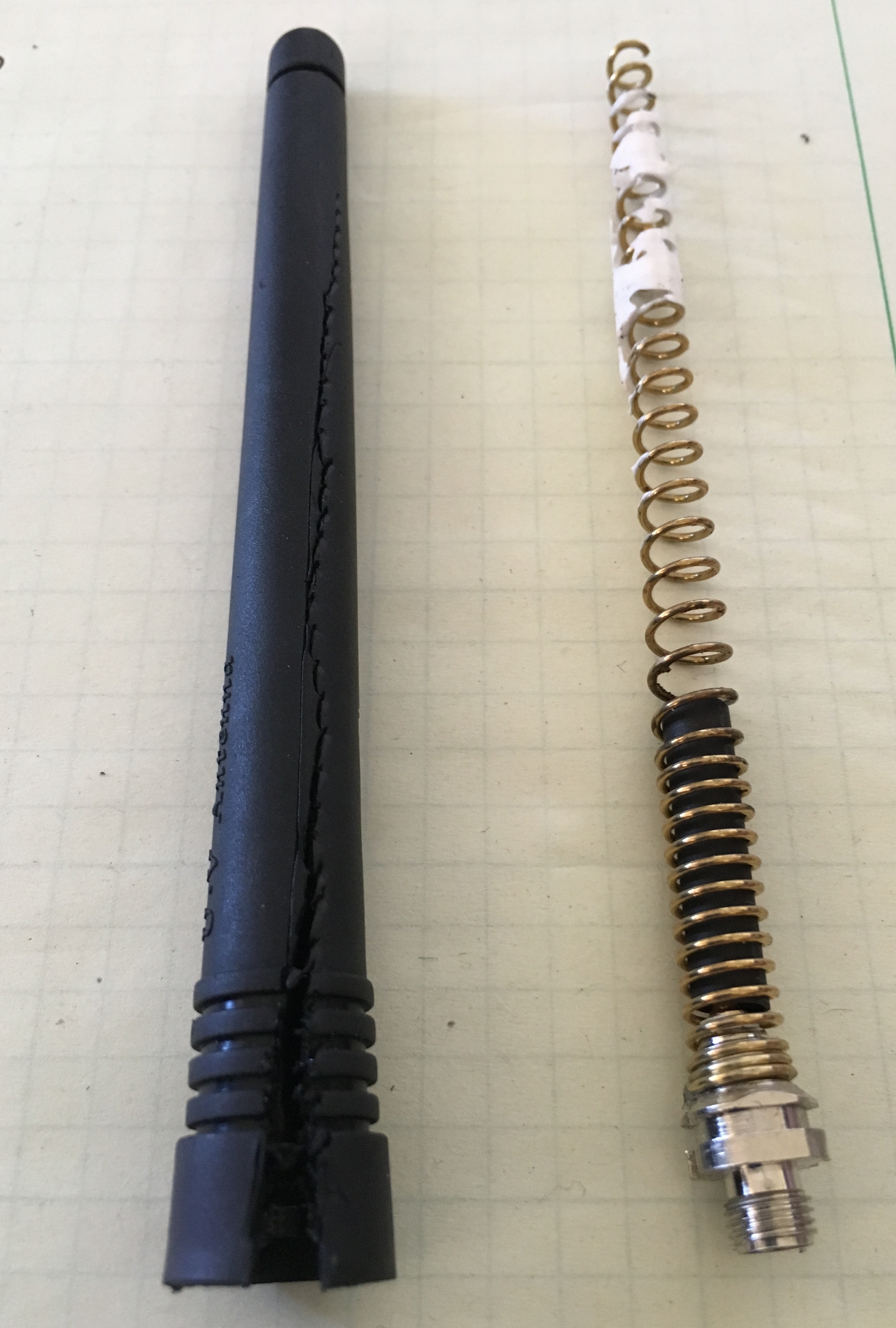
I started by dissecting a Baofeng UV-5R antenna, which took some aggressive action with a diagonal wire cutters to split the rubberized jacket near the bottom. After that, the jacket slid off to reveal the classic spiral antenna element inside. You can see some white adhesive near the top of the spiral element (upper right in the photo).
The Baofeng antenna had a female SMA connector.
Note: You can access high resolution versions of the photos in this article by clicking on them, allowing you to see lots of detail.
Yaesu FT-1DR Stock Antenna
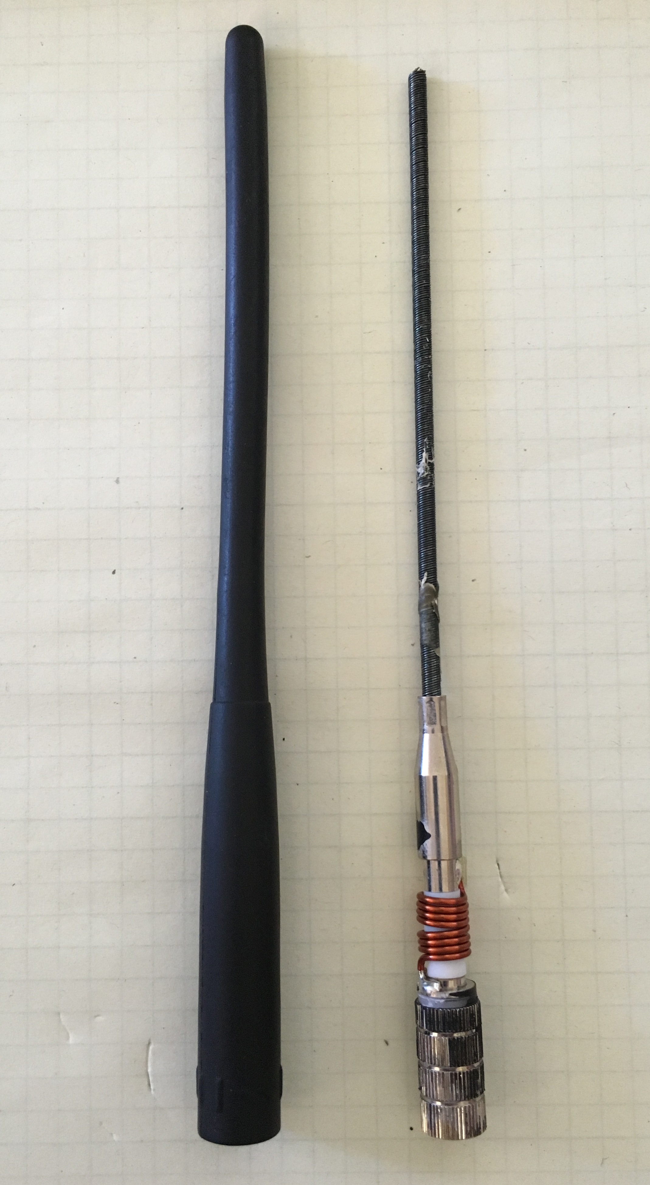
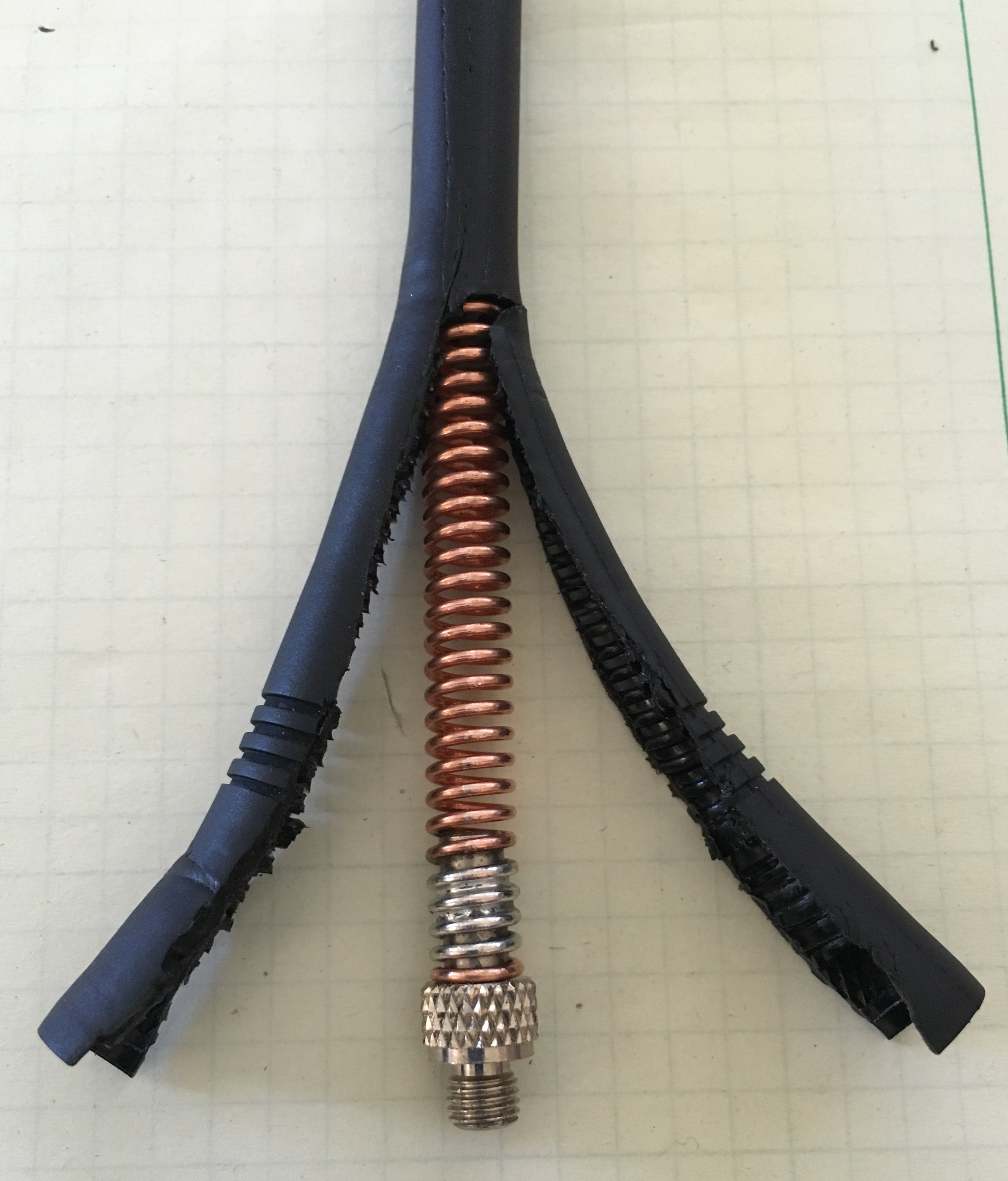
The Yaesu antenna was easy to disassemble. In fact, I chose this antenna because I noticed that the outside jacket had come loose and was starting to slide off the antenna. A steady pull on the cover exposed the antenna elements without any further antenna abuse. (I plan to reinstall the cover with a few dabs of glue and expect that it will continue to work fine.)
The construction of this antenna is quite different from the Baofeng. The main element is a very tightly-wound spring…so tight that I expect that it acts like a solid wire electrically. In other words, it doesn’t have the spiral configuration that makes the antenna act longer electrically. At the bottom of the antenna, there is a coil inserted in series with the radiating element (connects radiating element with the center pin of the SMA connector).
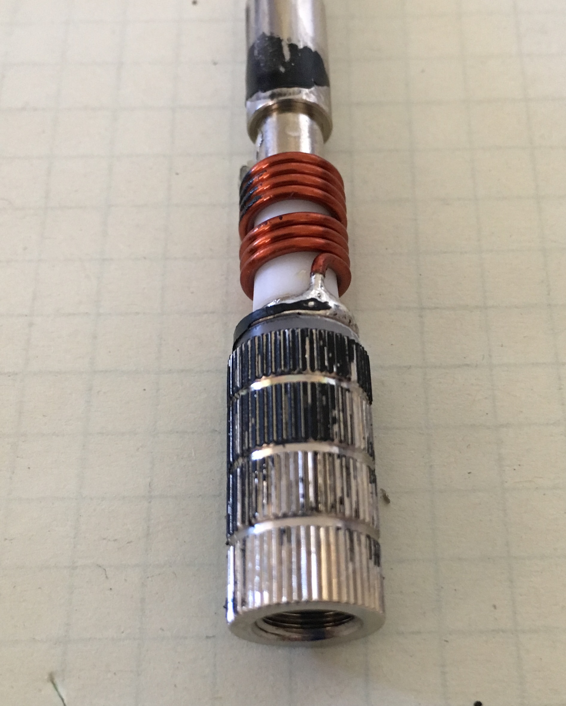
The photo to the right shows a closeup view of the male SMA connector and the coil.
Laird VHF Antenna
Next, I wondered if antennas for commercial radios had different design or construction techniques. Laird makes high-quality antennas for the mobile radio and other commercial markets, so I purchased one of their VHF rubber duck antennas to dissect. This model is intended for use with Motorola radios requiring a threaded antenna stud.
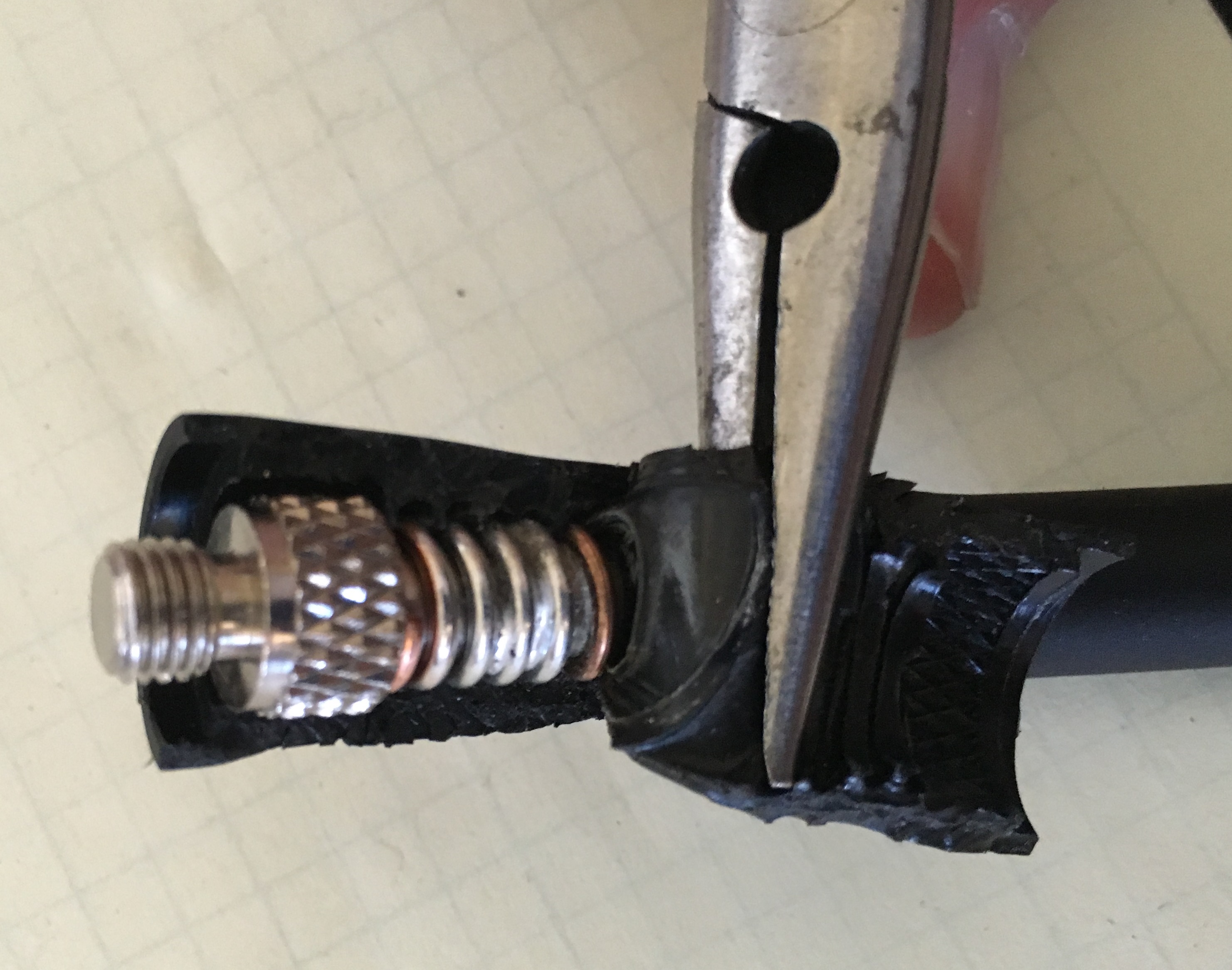
This antenna was a challenge to cut open. I used a sharp knife and diagonal pliers to cut the rubberized jacket and peeled it back using a needle-nose pliers. The rubberized coating was embedded into the spiral antenna element, so it did not come apart easily. It took over an hour fighting with the antenna and I gave up before getting the entire spiral element exposed.
The Laird antenna is clearly the sturdiest of the three antennas. The spiral element is much thicker than the Baofeng and the rubberized coating is tougher and molded tightly into the spiral element.
The Baofeng and Laird antennas use the same design concept…just take a spiral antenna element and apply a protective cover. However, the Laird construction was far superior, but not a surprise given that Baofeng is a low-cost provider in the ham radio (consumer) market.
My disappointment is with the Yaesu antenna. The antenna came apart after one year of not very heavy use. I expect I can put it back together with some adhesive, improving on the design in the process.
Anyway, I found this interesting and wanted to share it with you. What’s in your rubber duck?
73, Bob KØNR
The post What’s In Your Rubber Duck? appeared first on The KØNR Radio Site.
Bob Witte, KØNR, is a regular contributor to AmateurRadio.com and writes from Colorado, USA. Contact him at [email protected].
IARU HF World Championship contest
Mike Weir, VE9KK, is a regular contributor to AmateurRadio.com and writes from New Brunswick, Canada. Contact him at [email protected].
IARU HF World Championship contest
Mike Weir, VE9KK, is a regular contributor to AmateurRadio.com and writes from New Brunswick, Canada. Contact him at [email protected].
ICQ Podcast Episode 215 – Friedrichshafen 2016
In this episode, Martin M1MRB / W9ICQ is joined by Chris Howard M0TCH, Martin Rothwell M0SGL, Dan Romanchik KB6NU and Ed Durrant DD5LP to discuss the latest Amateur / Ham Radio news. Colin M6BOY rounds up the news in brief, and this episodes feature is Friedrichshafen 2016
- New Zealand Radio Hams Request 222-223 MHz
- 'No' to Lifetime Amateur Radio Licenses
- Rockford to Scramble All Police Radio Comms
- Andorra Returns to 60m, Gains 4m band, More Power on 6m
- Radio Caroline Special Event Station
- Clarification of RF LED Light Testing
- New RSGB Microwave Manager
- RF pollution from Solar Panels
- RSGB Training and Assessment Guide
Colin Butler, M6BOY, is the host of the ICQ Podcast, a weekly radio show about Amateur Radio. Contact him at [email protected].
Amateur Radio Weekly – Issue 119

Into the Digital age
One of the reasons for the rapid growth of DMR over D-Star and Fusion is the availability of relatively inexpensive DMR radios for amateur operators from Connect Systems and Tytera.
Digital Mobile Radio for Hams
A Radio Amateur’s guide to solar panels
Solar panels that cost over $6.00 per watt a decade ago are now available for less than $2.00 per watt. Solar is on the cusp of becoming mainstream.
Off Grid Ham
New podcast: The Workbench
Over the next several episodes, we will deep dive on information, tips, and gear needed to setup and equip your own workbench.
The Workbench
Elecraft KX2 Go Box
The project uses a water tight Pelican 1050 brand enclosure.
VA2SS
Solar Analysis Paralysis
Don’t have gear or antennas for the low-bands? Time to make an adjustment to your equipment and antenna portfolios.
KE9V
China fits final piece on world’s largest radio telescope
The 500m-wide Aperture Spherical Telescope, or FAST, is the size of 30 football fields.
BBC News
N9EWO Review: Icom IC-7300
You can usually get a better deal with more features in a Ham transceiver and the lack of tabletop receivers these days.
N9EWO
Dear ARRL, HR1301 is Hogwash
Your homeowners association can keep you from running a simple wire antenna.
N4AE
K8BL achieves Satellite WAS after 40 years
His contacts spanned 38 years, and he submitted QSL cards to claim the award.
ARRL
Serially, are you syncing or asyncing
Synchronous communication makes the receiver’s job easier by adding a third clock line to the ground and signal lines. This is the clock the transmitter uses to shift out the bits.
Hack A Day
Video
Yaesu FT-1000MP Repair
Follow along as Paul at Mr Carlson’s Lab shows the troubleshooting and repair steps involved in making a Yaesu FT-1000MP work again.
YouTube
24 hours of JT signal reception
This video shows which stations can be received using the JT65 and JT9 digital modes throughout 24 hours on 20m/14MHz, & how propagation changes during the day.
M0CUV
Amateur Radio Weekly is curated by Cale Mooth K4HCK. Sign up free to receive ham radio's most relevant news, projects, technology and events by e-mail each week at http://www.hamweekly.com.
Is Your Miniwhip Too High?
 |
| The Mini-Whip at University of Twente's (Netherlands) Remote Receiver |
A recent posting to Yahoo's ndblist Group described an interesting experiment by Dirk Claessens regarding the signal-to-noise ratio (SNR) versus height of his PAØRDT active whip. Dirk's tests were posted on Yahoo's Navtex DXing Group where some further interesting discussion seemed to confirm his findings.
Here is what Dirk discovered, backed-up with his graph data, clearly pointing to the 'ideal height' at his location ... and probably yours as well.
Hi all,
You may recall that to get rid of a source of QRM, my whip is now hanging from a rope-and-pulley system, about 5 .5 mtr from the house, at a height of 7 meter agl.
As the height of the whip can easily be changed, this is an ideal situation to test the behaviour of the whip wrt noise levels, optimal height etc..
I had done this test before some 4 years ago, but not very precise. Time to do it again, and documenting it.
What I also wanted to check, is if there were any noise sources of the own house possibly reaching the whip.
(how far does the "noise bubble" go in function of the height?)
The Perseus was tuned to 549 KHz Deutschlandfunk Nordkirchen, the station closest to 518.
2 markers were set, one to the signal, and a reference marker in a quiet spot nearby on 543 KHz, to get a reading for the noise floor.
The whip was then lowered in "1 meter each minute" steps, readings were taken and written to the marker file.
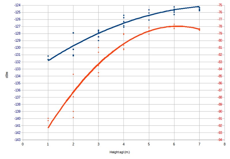
First the absolute values were plotted.
Note that: blue = noise floor, red = signal, and that the left and right axis scales have identical spans of 19dB, but are shifted, in order to get a compact graph.
We see that for a delta height of 6 meters:
-the noise floor goes up ~8dB, or 8/6 = 1.3 dB/m, almost linearly.
-the signal goes up ~14 dB, or 14/6 = 2.3 dB/m, clearly curved and showing a maximum at ~5..7 m.
The continuous lines are polynomic (2nd degree) regression lines.
The noise on the measurement values seems to increase with decreasing height. Was this caused by my body standing under the whip, and near to the whip for the lowest measurements??
What really matters of course, is the signal over noise value, this is plotted below:
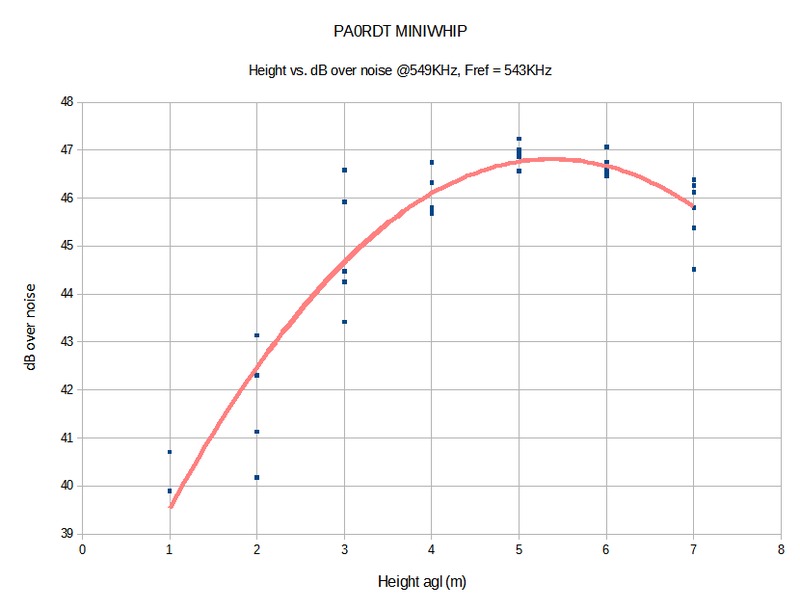
-Within a narrow 1 dB band, the curve shows a clear optimum in the region of 4..7 m agl, a familiar value often given as optimal by Roelof.
-The measurement was performed during the day and thus with ground wave propagation. As the whip is truly omnidirectional, I cannot see a reason why the behaviour would be different at low angle DX signals.
- At 5.5 meter from the house, the whip seems to be outside of the "noise bubble"
and later, following discussion:
I have just checked the noise floor again at 518 (with no signal present)
Perseus set to 125 kS/s, Span/RBW 25/30.5
Shield grounded: -125 dBm
Not grounded: -110 dBm
That's a whopping 15 dB difference!
I have also buried the coax ~20cm deep from the grounding point to where it enters the house.
The ideal height was also that recommended by Roelof, PAØRDT, originally and points out that one of antenna-building's most sacred commandments ... "the higher the better", is not always true!
I have often recommended this simple antenna for those looking for a very effective yet low-footprint receiving antenna for use on the LF and MF bands.
Much more information about Roelof's popular miniwhip may be found in previous blog discussions here.
Steve McDonald, VE7SL, is a regular contributor to AmateurRadio.com and writes from British Columbia, Canada. Contact him at [email protected].
 Ham Radio Deluxe |
 W5SWL Electronics |
 Ham Radio Prep |
 KB3IFH QSL Cards  Hip Ham Shirts  HamRadioAuctions HamRadioAuctions Reliance Antennas Reliance Antennas Enigma Shop Enigma Shop |  morseDX  Ni4L Antennas  R&L Electronics R&L Electronics antennas.us antennas.us QRV QRV |
- Matt W1MST, Managing Editor
