 |
 Giving Out Points Again!
Nice weather and an open schedule allowed for some radio time this weekend. The QRP ARCI Fall QSO Party made some buzz so I loaded up the gear and headed out by the lake. I put up an 88ft doublet in an inverted vee. I shoot a line over a tree limb at about 40ft and use that for the center and have two 17ft Crappie Poles that I use for end supports. That allows me to reorient the antenna to suit the conditions.

Ground Mount Closeup
One of the things I threw together is a simple mount for the crappie poles. I use a 2ft piece of PVC with a couple bolts inserted at right angles to one another at the base to keep the pole from going all the way through to the ground. The PVC is attached to a 3ft piece of aluminum angle iron that with 3 stainless steel hose clamps.

Crappie Pole End Supports
The poles are pretty limber and take a bit of a bend but do a good job of handling the 24 gauge teflon wire I use. As you can see in the pictures, the mounts do the job and don’t cost as much as commercial counterparts.
So it was a good day and I made a few contacts, enjoyed the outdoors and had a nice picnic lunch with my XYL down by the lake between QSO’s. The bands were pretty decent and I gave points to 20 of the more serious contestants out there.
72,
Kelly K4UPG PB #173
p.s. The Polar Bears will be out and on the air next weekend. Give a listen, hear?
Kelly McClelland, K4UPG, is a regular contributor to AmateurRadio.com and writes from Florida, USA. Contact him at [email protected].
Benoît Mandelbrot 1924-2010
")
Benoît Mandelbrot (courtesy of Rama via Wikimedia Commons)
It was sad to read late last night that Benoît Mandelbrot had just died. He was an outstanding mathematician and the individual that coined the term ‘fractal’. Obituaries can be found at the New York Times and the BBC.

A closer look into a Mandelbrot set. (Courtesy of Dr. Wolfgang Beyer and reproduced from Wikimedia Commons).
Beside the fractal he is perhaps most famous for the Mandlebrot Set (see an image above), which of course has fractal geometry. As a grad student, in the late ’80s and early ’90s, myself and a few others would run our computers in our spare time to generate Mandlebrot sets and we would zoom in and explore different regions. This was outside our main research work but these images were so beautiful it was fun to explore the set by mathematically zooming in to different regions. Professionally I still work in nonlinear science and I was sad to hear of the passing of Mandlebrot. His legacy to our understanding of the natural world and nonlinear science is considerable. Here is a clip of a BBC documentary that explains some of what he helped us understand.

Here is the man himself talking earlier this year at a TED talk.

If you are wondering if there is a connection to amateur radio. Well besides a better understanding of our natural world, Mandelbrot’s work gave us fractal antennas.
")
Fractal antenna (from a patent via Wikimedia Commons)


![]()
Alan Steele, VA3STL, is a regular contributor to AmateurRadio.com and writes from Ottawa, Ontario. Contact him at [email protected].
QRSS reception report

QRSS reception by ON5SL in Belgium
I received a reception report today via the KnightsQRSS e-mail list. Pierre, ON5SL, received my QRSS signal last night in Belgium along with the signals from WB3ANQ and W4HBK, as shown above. My signal is running QRSS3, that is a 3 second dit, and is the bottom trace.
My set-up was the homebrew transmitter putting out 160mW into the homebrew Z-match and an 88′ doublet (again homebrew). Helping match the short coax feed to the outside of the house to the doublet’s ladderline is an Elecraft BL2 balun.
Thanks goes to Pierre for the reception report. This is not the first time he has sent reception report, he sent me one in April and also one in March 2009. I am sure I speak for all who run such beacons that we all welcome and appreciate reception reports of our signals.


![]()
Alan Steele, VA3STL, is a regular contributor to AmateurRadio.com and writes from Ottawa, Ontario. Contact him at [email protected].
Bricked chip
Last night I received an email from Steve G0XAR to let me know that a replacement chip for the QRSS beacon had been programmed but not posted yet as he had been ill with a bad cold. However my impatience had got the better of me and I started wondering whether I could reprogram the chip myself. Perhaps this was the opportunity I needed to start playing with microcontrollers? The source code was on Hans G0UPL’s website, the development tools were all free. All I would need is a programmer, and I was sure I had seen circuits for microcontroller programmers knocked up from junk box parts on the web.
A bit of searching revealed that simple programmers for the AVR ATtiny13 chip can easily be made, such as this one built by Alan, VK2ZAY, but they require a parallel port, an antique piece of hardware that went out of use around the time Bill Gates made his first billion and is now as obsolete as the USB port will one day surely be.
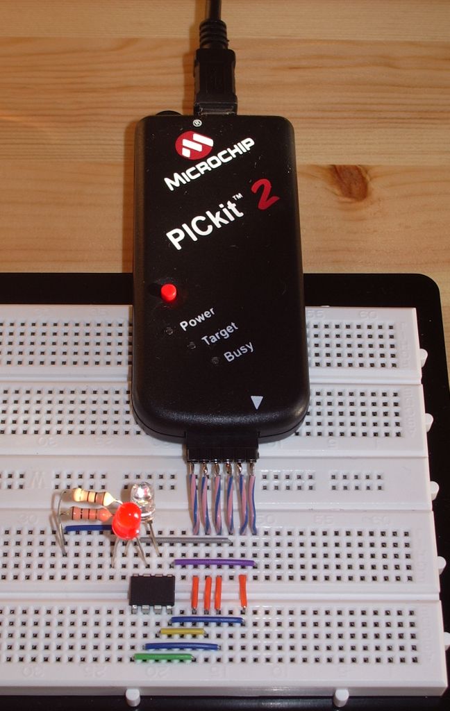
However I also came across an article that described how to program AVR microcontrollers using a Microchip PICkit2 programmer. A couple of years ago I obtained a PICkit2 because it was being offered in an electronics magazine for just the cost of the postage. Apart from running a couple of demo programs I had never done anything with it. What more of an excuse did I need?
In less than an hour I had downloaded and installed the AVR Studio software, WinAVR which was also needed, PK2AVRISP (the program which makes the PICkit2 look like an AVRISP or STK500 programmer), soldered six short leads to a 6-way header to attach to the PICkit2 and wired up the connections to the chip on my solderless breadboard. I already had a pair of virtual serial ports set up on the shack PC to use with the TrueTTY packet TNC so I was good to go.
PK2AVRISP detected my PICkit2 and I assigned it to one of the pair of virtual serial ports. The QRSS keyer program compiled in a couple of seconds and I was ready to program the chip. I selected the AVRISP programmer on the other end of the virtual serial port pair. The programmer read the signature from the chip and reported it was correct – an encouraging sign. Then I wrote the hex code into the flash memory. The write appeared to work but the verification failed with “WARNING: FLASH byte address 0×0006 is 0xFF (should be 0xCF).”
I searched forums for solutions to this error and tried various suggestions such as reducing the SPI clock speed or trying the STK500 option but I could not get past this error. One person claimed that he had somehow managed to program the chip despite the error so I put it back in the QRSS keyer, but now I just got a steady carrier with no keying at all. Oh dear!
I tried programming the code again this time using the avrdude command line programming software which is included with WinAVR but can’t be run directly from AVR Studio. This appeared to work, no error was displayed when the code was verified, but the chip still did not work when put back in the keyer.
To avoid moving the chip back and forth to test it after each programming attempt I tried programming a simple LED flasher into it so I could test it on the breadboard (hence the LEDs in the photo.) This works fine if I simply ignore the flash verification error. So the chip isn’t bricked. But why the keyer program doesn’t work is a mystery. I assume it should flash the LED on pin 3 in time with the keying, but it doesn’t.
Obviously a new chip will get the QRSS keyer working again but having spent all this time on trying to do it myself I would like to know why I couldn’t. Usually when something doesn’t work it is because I have made a stupid error, but I can’t see what I have done wrong. It’s so frustrating.
Julian Moss, G4ILO, is a regular contributor to AmateurRadio.com and writes from Cumbria, England. Contact him at [email protected].
QRSS shows 30m propagation conditions

W4HBK Grabber 15th Oct 2010
After reading about Julian’s QRSS activities I decided to put my 30m QRSS beacon back on the air which has had a break for a few months. This morning I checked W4HBK’s grabber and was pleased to see my signal getting into Pensacola, FL (see 10140020Hz in the image above). I then checked his 4 hour scan and saw something interesting, but not too surprising.

4hrs grabber scan by W4HBK 15th Oct. 2010
The scan clearly shows my 160mW signal stopped reaching Pensacola, from Ontario, at around 00:40am local time (0540 UTC) and then was received again at just before 5am (1000UTC). The closing down of the band in the early hours of the morning is to be expected, but it is nice to see the time and duration of the closing so clearly illustrated.
A few hours later I checked again and the 4 hour scan revealed other QRSS signals joining mine about 2 hours after mine had appeared on W4HBK’s grabber.

4hr W4HBK grabber scan a few hours later (15th Oct. 2010)
The 10 minute grabber screenshot below shows the number of signals being received by W4HBK and how popular QRSS has become, after the release of kits by Hans Summers, G0UPL, and Genesis Radio.

W4HBK grabber at 1629 UTC 15th Oct 2010
Comparing that to reception in Nova Scotia recorded by Vernon’s, VE1VDM, grabber it can be seen that not all the signals were visible. My trace was clear, but my QRSS station is perhaps the closest to Vernon’s station.

VE1VDM grabber at 1617UTC. 15th OCt 2010
This nicely shows how milliwatt QRSS signals reveal propagation conditions. I was also pleased to see how stable my homebrew QRSS transmitter still is (remember the frequency shift in the keying of my signal is about 6Hz). To help reduce/eliminate thermal drift I have the oscillator surrounded by pieces of polystyrene packing.


![]()
Alan Steele, VA3STL, is a regular contributor to AmateurRadio.com and writes from Ottawa, Ontario. Contact him at [email protected].
P5? Nope, PJ
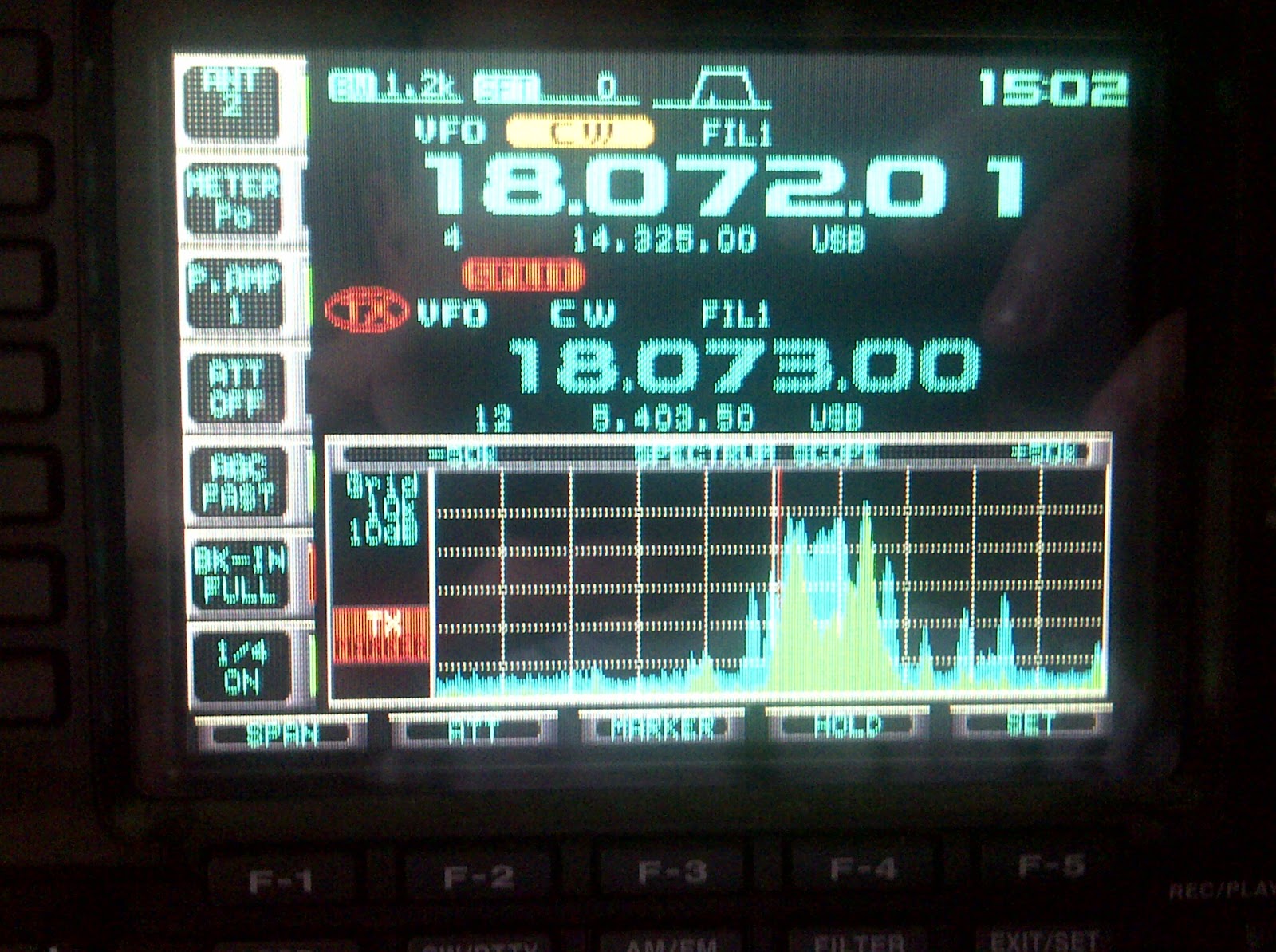 Now that the PJ operations have been underway for a while, you’d think that the pileups would have started to die down a bit. In some cases they have, but I was kind of surprised to see how big some of them remained. I guess it varies depending on band, propagation, and where you’re located, but this morning I saw PJ2T spotted on 17m CW and I figured I’d give him a call. He nice and loud, but he had a huge pileup. This is what my bandscope looked like.
By way of explanation, what you’re seeing is that I was tuned to 18.07201 MHz, which was where PJ2T was transmitting. I was set to call him split on 18.073Mhz. The big pile of green and light blue on the scale represents the other stations that are calling him. The scope was configured so that each white vertical line represents 10KHz of space. What you can see is that the callers for PJ2T were spread out over around 20Khz of space. Those of you who are DXers will appreciate how big that is, but normally for a “routine” DX operation you might see callers spread out to 2, 3, or maybe 5KHz. It’s only when a really “rare one” comes on that you typically see something like this. (Hence my reference to P5, North Korea, in the subject.) Oh, and keep in mind that these are only the callers that my radio can hear. Imagine what it must sound like on his end? I do want to say that the operator is doing a terrific job.
As a reminder, I’ve been collecting web sites and other internet presence information for the PJ DX operations on a special page here.
David Kozinn, K2DBK, is a regular contributor to AmateurRadio.com and writes from New Jersey, USA. Contact him at [email protected].
P5? Nope, PJ
Now that the PJ operations have been underway for a while, you’d think that the pileups would have started to die down a bit. In some cases they have, but I was kind of surprised to see how big some of them remained. I guess it varies depending on band, propagation, and where you’re located, but this morning I saw PJ2T spotted on 17m CW and I figured I’d give him a call. He nice and loud, but he had a huge pileup. This is what my bandscope looked like.
By way of explanation, what you’re seeing is that I was tuned to 18.07201 MHz, which was where PJ2T was transmitting. I was set to call him split on 18.073Mhz. The big pile of green and light blue on the scale represents the other stations that are calling him. The scope was configured so that each white vertical line represents 10KHz of space. What you can see is that the callers for PJ2T were spread out over around 20Khz of space. Those of you who are DXers will appreciate how big that is, but normally for a “routine” DX operation you might see callers spread out to 2, 3, or maybe 5KHz. It’s only when a really “rare one” comes on that you typically see something like this. (Hence my reference to P5, North Korea, in the subject.) Oh, and keep in mind that these are only the callers that my radio can hear. Imagine what it must sound like on his end? I do want to say that the operator is doing a terrific job.
As a reminder, I’ve been collecting web sites and other internet presence information for the PJ DX operations on a special page here.
David Kozinn, K2DBK, is a regular contributor to AmateurRadio.com and writes from New Jersey, USA. Contact him at [email protected].
 Ham Radio Deluxe |
 W5SWL Electronics |
 Ham Radio Prep |
 KB3IFH QSL Cards  Hip Ham Shirts  HamRadioAuctions HamRadioAuctions Reliance Antennas Reliance Antennas Enigma Shop Enigma Shop |  morseDX  Ni4L Antennas  R&L Electronics R&L Electronics antennas.us antennas.us QRV QRV |
- Matt W1MST, Managing Editor
