 |
 Bricked chip
Last night I received an email from Steve G0XAR to let me know that a replacement chip for the QRSS beacon had been programmed but not posted yet as he had been ill with a bad cold. However my impatience had got the better of me and I started wondering whether I could reprogram the chip myself. Perhaps this was the opportunity I needed to start playing with microcontrollers? The source code was on Hans G0UPL’s website, the development tools were all free. All I would need is a programmer, and I was sure I had seen circuits for microcontroller programmers knocked up from junk box parts on the web.
A bit of searching revealed that simple programmers for the AVR ATtiny13 chip can easily be made, such as this one built by Alan, VK2ZAY, but they require a parallel port, an antique piece of hardware that went out of use around the time Bill Gates made his first billion and is now as obsolete as the USB port will one day surely be.
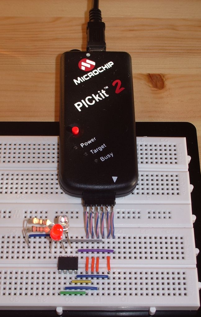
However I also came across an article that described how to program AVR microcontrollers using a Microchip PICkit2 programmer. A couple of years ago I obtained a PICkit2 because it was being offered in an electronics magazine for just the cost of the postage. Apart from running a couple of demo programs I had never done anything with it. What more of an excuse did I need?
In less than an hour I had downloaded and installed the AVR Studio software, WinAVR which was also needed, PK2AVRISP (the program which makes the PICkit2 look like an AVRISP or STK500 programmer), soldered six short leads to a 6-way header to attach to the PICkit2 and wired up the connections to the chip on my solderless breadboard. I already had a pair of virtual serial ports set up on the shack PC to use with the TrueTTY packet TNC so I was good to go.
PK2AVRISP detected my PICkit2 and I assigned it to one of the pair of virtual serial ports. The QRSS keyer program compiled in a couple of seconds and I was ready to program the chip. I selected the AVRISP programmer on the other end of the virtual serial port pair. The programmer read the signature from the chip and reported it was correct – an encouraging sign. Then I wrote the hex code into the flash memory. The write appeared to work but the verification failed with “WARNING: FLASH byte address 0×0006 is 0xFF (should be 0xCF).”
I searched forums for solutions to this error and tried various suggestions such as reducing the SPI clock speed or trying the STK500 option but I could not get past this error. One person claimed that he had somehow managed to program the chip despite the error so I put it back in the QRSS keyer, but now I just got a steady carrier with no keying at all. Oh dear!
I tried programming the code again this time using the avrdude command line programming software which is included with WinAVR but can’t be run directly from AVR Studio. This appeared to work, no error was displayed when the code was verified, but the chip still did not work when put back in the keyer.
To avoid moving the chip back and forth to test it after each programming attempt I tried programming a simple LED flasher into it so I could test it on the breadboard (hence the LEDs in the photo.) This works fine if I simply ignore the flash verification error. So the chip isn’t bricked. But why the keyer program doesn’t work is a mystery. I assume it should flash the LED on pin 3 in time with the keying, but it doesn’t.
Obviously a new chip will get the QRSS keyer working again but having spent all this time on trying to do it myself I would like to know why I couldn’t. Usually when something doesn’t work it is because I have made a stupid error, but I can’t see what I have done wrong. It’s so frustrating.
Julian Moss, G4ILO, is a regular contributor to AmateurRadio.com and writes from Cumbria, England. Contact him at [email protected].
QRSS shows 30m propagation conditions

W4HBK Grabber 15th Oct 2010
After reading about Julian’s QRSS activities I decided to put my 30m QRSS beacon back on the air which has had a break for a few months. This morning I checked W4HBK’s grabber and was pleased to see my signal getting into Pensacola, FL (see 10140020Hz in the image above). I then checked his 4 hour scan and saw something interesting, but not too surprising.

4hrs grabber scan by W4HBK 15th Oct. 2010
The scan clearly shows my 160mW signal stopped reaching Pensacola, from Ontario, at around 00:40am local time (0540 UTC) and then was received again at just before 5am (1000UTC). The closing down of the band in the early hours of the morning is to be expected, but it is nice to see the time and duration of the closing so clearly illustrated.
A few hours later I checked again and the 4 hour scan revealed other QRSS signals joining mine about 2 hours after mine had appeared on W4HBK’s grabber.

4hr W4HBK grabber scan a few hours later (15th Oct. 2010)
The 10 minute grabber screenshot below shows the number of signals being received by W4HBK and how popular QRSS has become, after the release of kits by Hans Summers, G0UPL, and Genesis Radio.

W4HBK grabber at 1629 UTC 15th Oct 2010
Comparing that to reception in Nova Scotia recorded by Vernon’s, VE1VDM, grabber it can be seen that not all the signals were visible. My trace was clear, but my QRSS station is perhaps the closest to Vernon’s station.

VE1VDM grabber at 1617UTC. 15th OCt 2010
This nicely shows how milliwatt QRSS signals reveal propagation conditions. I was also pleased to see how stable my homebrew QRSS transmitter still is (remember the frequency shift in the keying of my signal is about 6Hz). To help reduce/eliminate thermal drift I have the oscillator surrounded by pieces of polystyrene packing.


![]()
Alan Steele, VA3STL, is a regular contributor to AmateurRadio.com and writes from Ottawa, Ontario. Contact him at [email protected].
P5? Nope, PJ
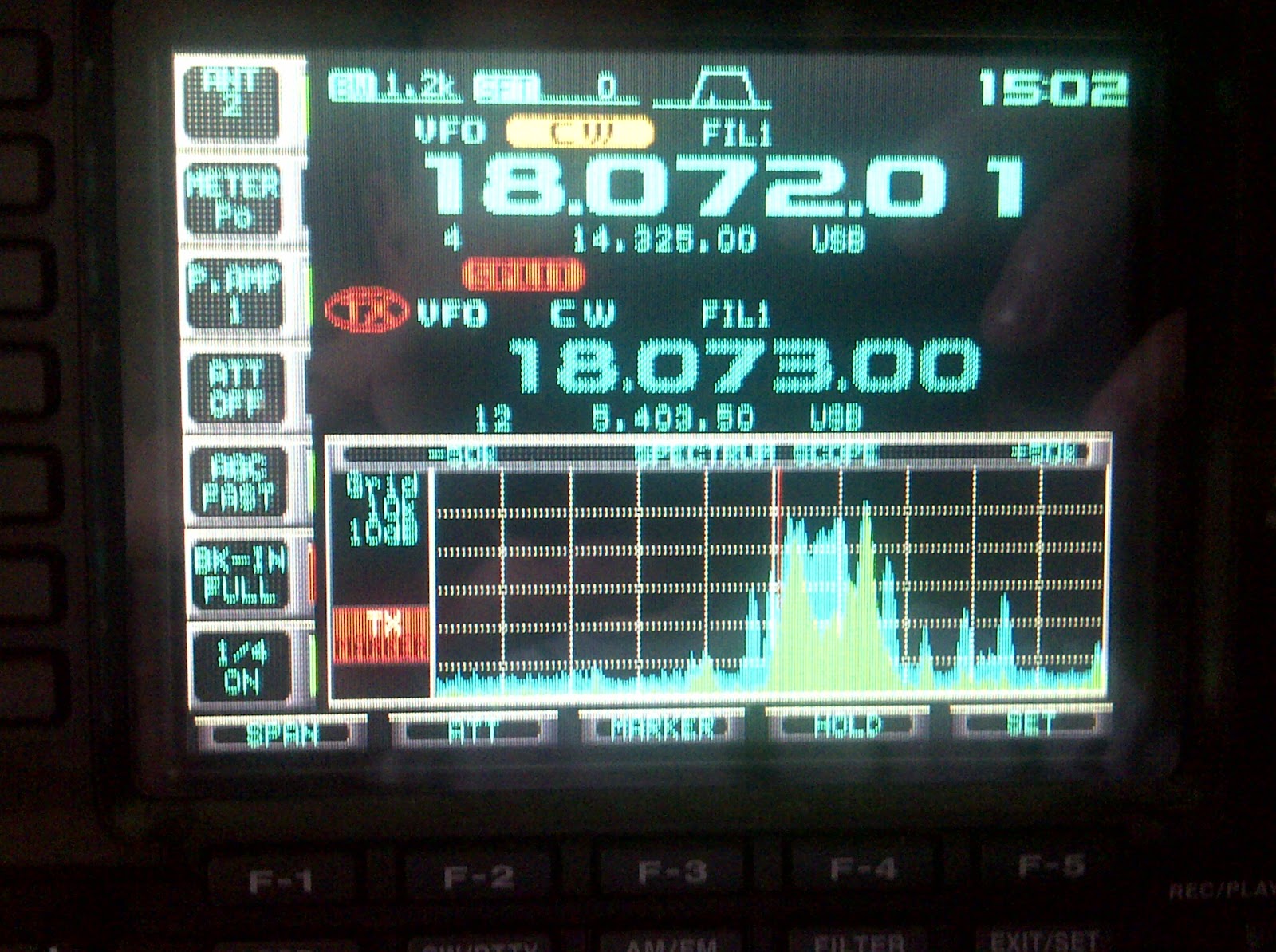 Now that the PJ operations have been underway for a while, you’d think that the pileups would have started to die down a bit. In some cases they have, but I was kind of surprised to see how big some of them remained. I guess it varies depending on band, propagation, and where you’re located, but this morning I saw PJ2T spotted on 17m CW and I figured I’d give him a call. He nice and loud, but he had a huge pileup. This is what my bandscope looked like.
By way of explanation, what you’re seeing is that I was tuned to 18.07201 MHz, which was where PJ2T was transmitting. I was set to call him split on 18.073Mhz. The big pile of green and light blue on the scale represents the other stations that are calling him. The scope was configured so that each white vertical line represents 10KHz of space. What you can see is that the callers for PJ2T were spread out over around 20Khz of space. Those of you who are DXers will appreciate how big that is, but normally for a “routine” DX operation you might see callers spread out to 2, 3, or maybe 5KHz. It’s only when a really “rare one” comes on that you typically see something like this. (Hence my reference to P5, North Korea, in the subject.) Oh, and keep in mind that these are only the callers that my radio can hear. Imagine what it must sound like on his end? I do want to say that the operator is doing a terrific job.
As a reminder, I’ve been collecting web sites and other internet presence information for the PJ DX operations on a special page here.
David Kozinn, K2DBK, is a regular contributor to AmateurRadio.com and writes from New Jersey, USA. Contact him at [email protected].
P5? Nope, PJ
Now that the PJ operations have been underway for a while, you’d think that the pileups would have started to die down a bit. In some cases they have, but I was kind of surprised to see how big some of them remained. I guess it varies depending on band, propagation, and where you’re located, but this morning I saw PJ2T spotted on 17m CW and I figured I’d give him a call. He nice and loud, but he had a huge pileup. This is what my bandscope looked like.
By way of explanation, what you’re seeing is that I was tuned to 18.07201 MHz, which was where PJ2T was transmitting. I was set to call him split on 18.073Mhz. The big pile of green and light blue on the scale represents the other stations that are calling him. The scope was configured so that each white vertical line represents 10KHz of space. What you can see is that the callers for PJ2T were spread out over around 20Khz of space. Those of you who are DXers will appreciate how big that is, but normally for a “routine” DX operation you might see callers spread out to 2, 3, or maybe 5KHz. It’s only when a really “rare one” comes on that you typically see something like this. (Hence my reference to P5, North Korea, in the subject.) Oh, and keep in mind that these are only the callers that my radio can hear. Imagine what it must sound like on his end? I do want to say that the operator is doing a terrific job.
As a reminder, I’ve been collecting web sites and other internet presence information for the PJ DX operations on a special page here.
David Kozinn, K2DBK, is a regular contributor to AmateurRadio.com and writes from New Jersey, USA. Contact him at [email protected].
FSDXA announce dxpedition to Kiritimati (Christmas Island/T32)

Last weekend at the RSGB’s convention, my friends at the Five Star DX Association (FSDXA) announced their next expedition to Kiritimati (Christmas Island) – T32 in the Pacific Ocean. The team aim to arrive 28th September, 2011 and depart 26th October, 2011.
The plan is to operate under the callsign, T32C. You can read more about the expedition at the official T32C site
I was very honoured to be invited to join the team, by Neville, G3NUG, though sadly I had to decline.
Having been involved on the inside of an FSDXA dxpedition before, I am absolutely certain that this will give DXers the very best opportunity to work T32. Hopefully, over the coming months, we’ll be able to bring more insights into the forthcoming operation.
You can see their first press release here
Tim Kirby, G4VXE, is a regular contributor to AmateurRadio.com and writes from Oxfordshire, England. Contact him at [email protected].
QRSS beacon progress
Yesterday I finished building the QRSS beacon kit board. The keyer chip sends the wrong callsign but it that was no reason not to build the kit. It’s a very easy kit to build although there are no fewer than five toroids to wind which is a lot for such a simple project. Some people hate winding toroids though I find them easy to do and can’t see what all the fuss is about.
The only other slight difficulty with the kit is that the potentiometer for setting the output power has leads that are too big for the holes in the PCB. This is mentioned in the instructions, where it is recommended to use component lead offcuts to extend the originals. My junk box was supplemented a few months ago with a Maplin bargain pack of assorted potentiometers and lo and behold it yielded a wirewound trimpot of exactly the right value that perfectly fitted the PCB holes. So I used that instead.
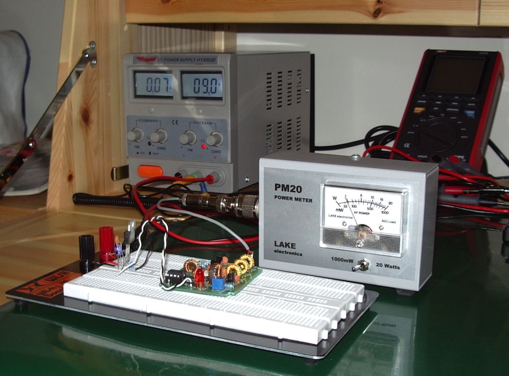
When the board was finished I powered it up using my bench power supply and PM20 QRP absorption wattmeter. In the photo I have breadboarded a regulator from 9V down to 5V as I was toying with the idea of running the beacon from a rechargeable PP3 battery (the board will fit into a case I have which has an integral PP3 battery holder) and wanted to see how much heat the regulator would dissipate.
I found that I could get a maximum of just under 100mW from the beacon with about 120mA current drawn. This is a little less than the specification. The instructions suggest that a bit more than 100mW should be possible, but the shortfall isn’t enough to worry about. For longer battery life I will run the beacon at 50mW which draws a current of around 65mA.
To get the transmitter on frequency and set up the mark/space frequency shift I used my K3 and QRSS VD software. The signal, even on the dummy load of the power meter, was very loud which was helpful getting it into the ball park. I had to disconnect the antenna, switch in the attenuator and back off the RF gain to reduce the signal to a level where I could fine-tune the frequency and see what the signal would look like on the air.
And here it is, sending G4LIO! It’s a bit frustrating not being able to connect it to an antenna and put it on the air because of the wrong callsign. I’ve been promised a new chip and I practically snatched the post out of the hands of the postwoman but it hasn’t come yet. In the meantime I can think about putting the beacon into a nice box. Forget winding toroids, for me that is the hardest and least enjoyable part of any constructional project!
Julian Moss, G4ILO, is a regular contributor to AmateurRadio.com and writes from Cumbria, England. Contact him at [email protected].
144-MHz SoftRock

144-MHz SoftRock Ensemble II VHF by KB9YIG and VE3NEA Rocky 3.6. Yup, that’s W3APL/B (off the back of the beam) and WA1ZMS/B in the same waterfall. How cool is that?! More later… This has many implications for many projects!
Ethan Miller, K8GU, is a regular contributor to AmateurRadio.com and writes from Maryland, USA. Contact him at [email protected].
 Ham Radio Deluxe |
 W5SWL Electronics |
 Ham Radio Prep |
 KB3IFH QSL Cards  Hip Ham Shirts  HamRadioAuctions HamRadioAuctions Reliance Antennas Reliance Antennas Enigma Shop Enigma Shop |  morseDX  Ni4L Antennas  R&L Electronics R&L Electronics antennas.us antennas.us QRV QRV |
- Matt W1MST, Managing Editor
