 |
 Handiham World for 9 February 2011
Welcome to Handiham World!

We’re all familiar with cartoons showing evolution with a sea creature crawling up onto the land and evolving into a succession of higher creatures, finally ending up with a guy talking on a cell phone or some such silly thing. Books go through an evolutionary process, as is shown in the accompanying photo. I lined up three editions of the ARRL Handbook, one from 1944, when World War 2 was still a year from winding down, another from 1989, when my son Will, KC0LJL, was born, and the very newest one, the 2011edition. I thought it would be fun to take a look at how this long-standing, highly respected reference book evolved through the post- WW2 era. Of course with only three samples, this is anything but a scholarly assessment. Still, it will be fun to compare these three books, so let’s get started.
How they look
For those of you listening on the podcast, the 1944 edition is titled “The radio amateur’s handbook”. It’s a paperback edition with a red cover and a large blue ARRL diamond logo. It stands out from the other two books immediately because of its much smaller dimensions. It’s probably just over one half the dimensional size of the others, and has far fewer pages, under 500. The edition year, 1944, is featured in white letters on the red background. Below that is the real shocker, the $1 price.
The 1989 “ARRL Handbook”, renamed to make the title simpler and showcase the ARRL, is a bigger hardcover book, blue at the top and fading down to green at the bottom. A montage of color cover pictures tell the story of amateur radio’s many different facets, including Field Day operation, VHF/UHF, a circuit board with integrated circuits, a rocket taking off, satellite tracking software, and on the air operation. The familiar ARRL logo is still there, but smaller. I’m going to guess that there are probably 1200+ pages. The price in the upper right corner says $21.
The 2011 “ARRL Handbook” looks to be about the same size as the 1989 model, but has in excess of 1400 pages, perhaps on slightly thinner but higher quality paper. It’s a sedate monochrome blue hard cover but has a flashy, attractive full-color jacket with a montage of a high-power transmitting tube, what looks like a construction project for a small rig, a guy climbing a tower while silhouetted against a fiery sunset, an SWR meter construction project, and a picture of the CD that is enclosed. More about that later. The ARRL logo is still there, up near the top. The price? $49.95. It’s no longer on the front, but found in small type on the back along with the ISBN and bar code. For bookstore browsers, there’s a handy simplified table of contents right on the back cover of the jacket.
Inside
1944: Microscopic print size is arranged into two columns per page. There are line drawings and schematics sprinkled throughout, along with black and white photos. The text describing the figures is in a font that’s even smaller than the text in the body of each section. They must have had better eyes back in 1944 to see that fine print! (I wouldn’t know, since I wasn’t even born yet.) One standout feature of the older handbooks is the pages of vacuum tube diagrams near the back of the book. This edition also includes many pages of ads for various radios and components of the day. If there is interest, I can take a look at some of those another time. One theme that seems to hold in every Handbook edition is the construction articles. They are always practical, well-written, and useful. Of course they are all vacuum tube projects, where point to point wiring was very common, as opposed to the circuit boards we use today. The construction article authors didn’t do too much hand-holding. You had to know how to read the schematics and were left to your devices as to the final circuit layout and enclosure, though the photos offered ideas.
1989: We are now clearly into the era of solid state electronics. At least the typeface is a little more readable. Like the 1944 book, this one features black and white line drawing and photos. Both the tube diagrams and the advertising section have disappeared from the back of the book. There are some templates that might be used in various construction projects – always a mainstay of the Handbook. Although the projects are as exciting and useful as ever, many still require a fair amount of builder savvy. It’s not like putting a kit together!
2011: The very newest, most current Handbook doesn’t disappoint! As big dimensionally as the 1989 version, it runs in excess of 1,400 pages and has black and white line drawings, schematics, and photos throughout. The print quality is excellent probably because the paper has a smoother finish. This makes the photos sharper and the line drawings and graphs stand out. The typeface is still on the smallish side, but the comments that accompany the figures are in a bold Arial-family font that is easily read. The cover is a subdued blue, but the paper jacket is a full-color glossy montage of a high-power transmitting tube, the “2011” in huge letters, a couple of construction projects, and a delightful photo of a guy on a tower with stacked beams, silhouetted against a fiery sunset. The ARRL diamond is there, too, as well as the phrase ” The Comprehensive RF Engineering Reference”, which is a clue to the excellent selection of need to have available material inside. It also proclaims, “Expanded and Revised Edition!” Notice the exclamation point, because it really is the best, most useful (and accessible) version of the ARRL Handbook ever. This book is for those of us who want to know how things work. Sure, you can skip past the manufacturer’s specs when you shop for a transceiver and just look at the knobs and buttons on the front panel, but if you would like to learn more about what those specs mean, the Handbook will help you out. The many construction projects include some that are pretty easy, and others that will keep you busy all winter long. Best of all, everything in the book is included on a searchable compact disk that is in a disk envelope at the back of the book. The file format is PDF, but since the entire text is searchable, that means that the embedded text should be available for reading with accessibility tools like screen readers. At Radio Camp this summer we will put this disk to the test, as we will have several really experienced JAWS users, and perhaps some Window-Eyes users as well. A folder on the CD even includes companion software.
It is interesting to follow the evolution of the Handbook, because it is a mainstay of amateur radio and can be used as a mirror into which we look to see ourselves! The amateur operator of 2011 operates more modes and uses new technologies, but still has the same spirit of friendship, communication, public service, and fun!
Patrick Tice, WA0TDA Handiham System Manager [email protected]
New block on Handiham.org

What is a “new block”, anyway? Well, the Handiham website uses the open-source content management system called “Drupal”, which was recommended a few years ago by Phil Temples, K9HI. Among Phil’s volunteer duties is helping with our website maintenance. Drupal has proven to be a very good system, since I can place stories online from any computer that has an internet connection. One of the features of the Drupal system is that a “block” containing special website features or information can be placed on the site and remain independent of the regular website content. The “members only” log in is a block, as is the “Tek Talk Audio” block. A sighted user will find these blocks on the left or right sidebar, with the main news content of the site down the center. Mobile users will not see all of this sidebar content, but will see the callsign lookup block.
The new block we have added is called “Remote Base Status”, and it appears in the right sidebar at the top. It is designed to provide a quick link to the current posted status of the two Handiham remote base internet stations, W0EQO and W0ZSW. If you checked early this morning, you would find out that W0ZSW is offline, while W0EQO is working normally. The block also includes HTML that I have written to “Report a problem” in case you find that one of the stations is not working. Clicking that link will open your email program and start an empty email addressed to me at [email protected] with “Remote Base Problem Report” already filled in as the subject. Since I only check the systems once or twice a day, I may not know when there has been a failure, so I appreciate your help in letting us know when something is not working right.
The remote base status page is located at node 1005. Drupal keeps web stories in a database and each story has a node number.
Beneath the Drupal system, we also maintain a static website that is optimized for our blind users. I edit it with Microsoft Expression Web and FrontPage. The index, or starting page, on this members site also has a remote base status report, but it may not be updated as frequently because it must be done from my main computer, where I maintain copies of the files that I edit each week.

Getting to the members section requires logging in on the Drupal website, and there is another “block” called “Members Only Section”, where you will find a place for your username and password if you are a Handiham member. This is a member service and is set up by staff only for our members with disabilities. It is not possible to create your own username and password as can be done on some other websites. Once a Handiham member logs in, the Members Only Section block will display links to the Book & Tape List, Daisy Materials (which has just been added to this block), Manuals, and the Members Only Website. This block appears to sighted users in the upper part of the left sidebar. Mobile users will see it near the top of the page. Some blind users prefer the mobile version of the Handiham website for its ease of navigation. It works great on an iPod or iPhone, where you can use the VoiceOver screenreader.
As we work to keep our website accessible, I would like to hear how things are working for our users. Please email me anytime at [email protected] with suggestions. I will put them in a folder and Phil and I can then try to figure out how we can make things even better.
Troubleshooting 101: Coax
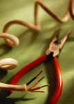
One of my many faults is forgetting how newcomers to ham radio might not know even the most basic of practical troubleshooting skills. Since I’ve been a ham since 1967, I’ve pretty well run into enough problems to build up at least basic troubleshooting skills. In fact, most “seasoned” ops know this stuff and we tend to just assume that everyone else should know it, too.
Of course that is wrong. Everyone needs to learn new things, and we have to understand that what is old hat to us might be brand-new to someone else. It is with that thought in mind that I am going to take a minute to explain how to check a piece of coaxial cable for continuity.
To run this test, you need:
 | a piece of coaxial cable |
| a multimeter with a continuity buzzer or ohmmeter |
| a short clip lead with an alligator clip on each end |
It is always suspicious when your SWR readings jump up and down or change radically when you haven’t changed frequencies. Perhaps you are listening on a frequency and the signal cuts out and then comes back in as if a switch were being turned off and on. These symptoms could mean that you have a feedline problem. Troubleshooting a piece of coaxial cable, the most common feedline used by radio amateurs, is easy, but you have to know how to do it. You can practice on a short piece of coax, perhaps a jumper cable that you have in your junk drawer.
Start by making sure you have a working multimeter (with an audible continuity buzzer if you are blind) and a clip lead. Both can be found at Radio Shack. Before you test the coax, you are going to test the multimeter and the clip lead! Select the “continuity” or ohms setting on the multimeter and make sure it is turned on if your meter has an on/off switch. Then take the clip lead and connect one clip to the positive lead on the meter and the other to the negative lead. You should hear the familiar tone or buzz that indicates that there is a short between the meter leads. If you don’t hear the tone (or see the needle swing to indicate a low-resistance short), check to make sure that the meter is working by touching the positive and negative probes together. If there is still no sound, check the settings on the meter and the condition of the meter’s internal battery. If the meter works but there is no continuity between the clips on the clip lead, find another clip lead.
Once you are satisfied that the meter and clip lead are good to go, take your test piece of coax, which should not be connected to anything on either end, and touch one meter probe to the center conductor pin on one end of the coax and the other meter probe to the outer shield of the body of the connector. You should hear nothing and the connection should be open. If there is a sound and the meter indicates a short, try again and make sure you did not accidentally short the two meter probe to each other while trying to touch one to the center pin and the other to the outside of the coax connector. If there is still a sound and the meter indicates a short, then the coax is shorted. Usually this happens when a PL-259 connector is installed improperly and a thread of coax braid shorts to the center conductor inside the plug’s housing. The connector may need replacement.
But let’s say that your coax passes this first test and you have no short between the coax center conductor and the shield. Your next step is to take the clip lead and short the coax on one end by connecting it between the center conductor of the PL-259 to the outer shield. Once that is secure, test again on the other end of the coax by using the multimeter. Connect one probe to the center conductor and the other to the shield. You should hear the buzzer and see the meter indicates a short. If there is no short, this indicates that the coax is open somewhere along its length, or else you have not connected the clip leads securely or made a good contact with the probes. Check both of these and try again just to be sure. If you still have no short in this test, then the coax has an open circuit. Perhaps the center conductor broke, but more likely the problem is in or near one of the two PL-259 connectors. These are the typical spots where a connection either shorts or opens because that is where we handle the connectors when connecting and disconnecting the cable and that is where most of the stress and flexing of the cable is likely to take place.
If your test cable passed both tests, you are not quite home free yet. Sometimes cables are intermittent, and may short or open when you flex them. If you can perform both tests while flexing the coax, you may be able to determine if the cable is intermittent.
Now that you have learned the basic procedure, there are some things to know about before you test feedlines that are in daily use in your ham shack.
| Always eliminate shock hazards by disconnecting all equipment from the AC power mains by unplugging it from the wall outlet before starting. The reason is that if there is an equipment defect, you can get shocked when you place one hand on an antenna connector and the other on equipment that is plugged into the AC outlet or otherwise connected to some accessory that is also plugged in. Remember that the shield side of an antenna system’s feedline may be grounded, and leaving equipment plugged in can place you between ground and AC voltage, which could be very dangerous. |
| If you are testing an antenna feedline, think about what is connected on the far end, at the antenna. Remember that a balun will show up as a short when you do the multimeter test. Some antenna matching schemes also show up as a DC short. If you place the test probes across a feedline connected to a balun on the other end, you can expect to find a short. If there is an open circuit instead, you can then start checking to find out where it is. However, you cannot be sure the coax isn’t shorted somewhere other than where it should be at the balun. |
| To complete the test, the coax may need to be disconnected from the antenna. Once that is done, the test can proceed as you performed it with the test piece that we first used to practice. |
Most failures occur at the ends of the cable, near the plugs, as we already said. But failures where cables run outdoors can also happen when rabbits or rodents decide to nibble on your feedline for lunch. Other failures can happen when the constant flexing of the cable in the wind breaks the connection to the antenna or balun.
Once you finish troubleshooting and have made the necessary repairs, the coax should be connected to the radio equipment and then the equipment should be plugged back into the AC plug as a final step.
Of course coax can fail in other more subtle and hard to diagnose ways. Water entering the coax from a broken seal can be harder to detect with the multimeter method. Careful inspection may be required to look for the distinctive corrosion and deterioration of the copper braid that is associated with moisture inside the coax jacket. The coax may have also just deteriorated over time, especially if it has been exposed to the weather over many years. Telltale signs of oxidation or cracking of the jacket indicate that it’s time to replace your feedline, even though it may pass the multimeter test. Remember that you are basically just testing a DC connection with your multimeter. When the feedline carries RF energy it will behave differently, especially if it has deteriorated due to age and weather.
You will be surprised at how much basic troubleshooting can be done with simple tools like a multimeter and a clip lead!
Pat Tice, WA0TDA, is the manager of HANDI-HAM and a regular contributor to AmateurRadio.com. Contact him at [email protected].
Screaming for help
I wonder if readers could help me locate a couple of software utilities I need for current projects?
Screamer 1.7 PIC boot loader (or successor.) This was developed by or for Sparkfun, who have version 1.6 on their website. Unfortunately it only allows serial ports COM1 – COM6, which is not convenient for me due to all the COM ports dedicated to radios and TNCs on my shack computer. Forum posts mention a version 1.7 that lets you enter larger COM port numbers but the links to it are now dead. The version 1.6 download includes VB6 source code so I could fix the problem myself except that I only have VB.NET which is totally incompatible with it (don’t you just love Microsoft?) So does anyone know where I can find a copy of Screamer 1.7 or later?
Programming software for Friendcom FC-201SA UHF Transceiver Module. I purchased one of these a few months ago but have only just got round to using it. However it is operating on its default frequency of 430.000MHz. There is a serial interface that can be used to set the frequency in each of the 16 channels and also set the channel. The manual describes the module’s command set but I don’t really want to spend days writing a program for it. The manual also mentions programming software but it was not supplied when I purchased the module from Elcom Research and their website is now defunct. I can’t find the utility on the download page of the Friendcom website and the email I sent to Friendcom did not receive an answer. Does anyone know where I can find a copy of this software?
In case anyone has what I’m looking for and is thinking of emailing software to me, please contact me first. Google doesn’t just block executable attachments, it blocks the entire email so I’d never even know you’d written. The trick is to put it into a zip file and then change the file extension to something other than zip.
Julian Moss, G4ILO, is a regular contributor to AmateurRadio.com and writes from Cumbria, England. Contact him at [email protected].
Intro to multimeter use
Collin over at Make: is at it again. Here is a great little seven minute intro on how to use a multimeter.
If you’re an experienced ham, then you can indeed skip this one. I like the basic videos that Make: is putting together to use when I teach hams.
If you don’t know it already, you can go to the Make: website http://makezine.com/ and download the videos and share with your friends and students. I started putting these videos on basic electronics on a DVD for students and they have REALLY learned quite a bit.
If you know of any other good videos, post below and share the knowledge!
Jonathan Hardy, KB1KIX, is a regular contributor to AmateurRadio.com and writes from Connecticut, USA. Contact him at [email protected].
The Hepburn tropo site was right!
In my last post, I said that the Hepburn tropo site was pointing towards good VHF/UHF conditions from the south-west of the UK towards Spain by last weekend. When I got on to 432MHz SSB, late yesterday morning, I heard one or two people talking about good conditions to the south. I had a quick chat with Mike, G8CUL operating at the Harwell club as G3PIA and he mentioned that there had been a Spanish contest earlier on and that some contacts had been made. Unfortunately by the time I got on, if conditions were still there, there was no activity.
I enjoyed making a few contacts in the 432MHz AFS contest over reasonable distances; G4ZTR and G1OGY/P both in Essex, G4ODA in Lincolnshire and G0HFX/P in Devon being some of the more distant ones. Good to work Pete, 2E0SQL trying out his new system too. Before heading over the Cotswolds to see Mum, I had a couple of quick 70MHz QSOs; G8FAK near Milton Keynes and G3NPI at Buckingham.
I’d pretty much given up/forgotten about the tropo when we came back in the evening until I saw a post from Ken, G0PPM on Facebook saying that he was hearing a French station on 145MHz FM. Thought it was worth a listen, so I popped upstairs to see if I could hear anything.
The Swiss beacon, HB9HB was coming through nicely, but CQ calls in that direction on both 144 and 432MHz didn’t result in any QSOs. However, just as I was about to give up, I heard a weakish call on 144.300 – I could tell it was a French station and the signals came up a little as I turned my beam to the south and I was able to get the callsign as F1MOZ. That triggered something in the memory banks – and a quick Google confirmed that he was located in IN93. Signals weren’t great on my little 5element, but I was delighted (and faintly surprised) when he came back and gave me a report!
Driving to work this morning, I was still hearing some tropo and there was a French repeater coming through on 145.650. I listened for a while and it turned out to be F5ZNN, located to the east of Paris.
Tim Kirby, G4VXE, is a regular contributor to AmateurRadio.com and writes from Oxfordshire, England. Contact him at [email protected].
USB technology du jour
Getting a radio to communicate reliably with a computer proves to be a difficult task for some people. The trouble seems to be caused by USB to serial adapters that corrupt the data when used with certain software or at certain speeds. Whenever these problems are discussed in amateur forums inevitably the question of why radio manufacturers don’t build USB interfaces into their radios (as Icom and Kenwood have started to do) is raised. I think this is a very short sighted view that really does nothing to solve the problem.
To begin, let’s deal with the argument that goes “why force users to buy a serial to USB adapter when serial ports have been obsolete for years.” Users have to use something to connect the radio to the computer and the only physical difference between a serial to USB adapter and a serial cable is that one end of the former is a bit fatter to accommodate the USB electronics. There is little difference in cost between the two cables. Furthermore, just because PCs don’t come with serial ports doesn’t mean that they are obsolete. My shack PC has four – soon hopefully to be increased to six if I can get it to accept the two port board I removed when I upgraded to four as an addition – and installing them is easily within the capabilities of any radio amateur. If you use a laptop you don’t have that choice, true enough, but why force a change on everybody because some people choose shack PCs that have limited expandability?
But the main reason why I think building USB into the radio isn’t the solution is that it doesn’t address the problem. It’s USB – either the hardware or its drivers – that is causing the connectivity problems in the first place. If an external adapter cable is used, users can try a different type if the one they have is not working correctly. If the USB hardware is built into the radio then they are stuck with it and reliant on finding a software solution. That might be a matter of getting the manufacturer to fix its drivers, which is not so easy.
Another reason why building USB into the radio is a bad idea is that it limits choices for users. If you want to connect your radio anything other than a PC, something like a MicroHam controller or a remote control over internet device for example, then you’re stuffed if you’ve got a USB port. Some owners of Kenwood’s new TH-D72 APRS handheld have already found that Kenwood’s decision to provide a USB rather than a serial interface to the radio’s internal TNC means they can’t use Bluetooth to link it to APRS software on another mobile device.
Whenever I argue that switching to USB is a bad thing someone always counters the argument by saying USB can provide a wide bandwidth connection that can handle other things such as audio. As somebody who has sometimes had three USB sound devices attached to my PC I can certainly see how a one cable interface between rig and computer might seem attractive, especially to those who believe that sound card modes need something like a RigBlaster. And I would agree that a fast interface would be a nice thing to have if it was one that was a true universal standard like, say, Ethernet.
But if we are talking about USB, most of my arguments still apply. Built-in USB limits choices. An analogue audio input and output lets you interface audio with other things such as digital voice recorders, TNCs and VOIP devices for remote control over the internet. We’re hams, we’re supposed to be able to handle technical stuff, do we really need plug and play interfaces for our radios?
USB is a technology du jour. It keeps changing, whereas RS-232 and analogue audio are permanent standards. USB 1.0 devices seem still to work with USB 2.0 but now USB 3.0 is starting to appear and it remains to be seen how backwards compatible that will be with older USB devices. Who knows what the computers of 10 or 15 years time will be equipped with? It may not be USB anything but something completely different.
Finally there is the fact that USB depends on software to work: drivers that are operating system dependent. Most serial to USB hardware is at least supported by operating systems other than Windows “out of the box.” I don’t have the experience to know whether that is true for USB interfaces that carry audio or other information. Is anyone using their IC-7600 or TS-590 under Mac OS or Linux?
Even if the manufacturer-supplied drivers work for Windows today, will they work on the latest version of Windows in 10 or 15 years time? If not, will the manufacturer of the radio provide new drivers once the radio is an obsolete model? I’ll bet a perfect but unusable as no longer supported scanner that they won’t. I’m equally sure that I’ll still be able to interface my K3’s RS-232 serial port and analogue line input/output to whatever computing hardware and operating system I’m using then.
Julian Moss, G4ILO, is a regular contributor to AmateurRadio.com and writes from Cumbria, England. Contact him at [email protected].
FUNcube Dongle – sold out in 49 seconds
The latest batch of 135 of Howard Long G6LVB’s FUNcube Dongle Pros sold out a few hours ago in less than a minute!
The FUNcube Dongle Pro is a tiny SDR receiver for the frequency range 64 to 1,700MHz. It’s the “ground segment” of the AMSAT-UK FUNcube satellite project.

FUNcube Dongle Pro
The best source of information about what to do with the FUNcube dongle and how to get hold of one is the Yahoogroup. Howard is active on the list and the main website and is quick to join the discussion and respond to all manner of queries.
The FUNcube Yahoogroup page explains the background and aim to the project:
AMSAT-UK’s FUNcube is an educational single cubesat project with the goal of enthusing and educating young people about radio, space, physics and electronics.
It will support the educational Science, Technology, Engineering and Maths (STEM) initiatives and provide an additional resource for the GB4FUN Mobile Communications Centre.
The target audience consists of primary and secondary school pupils and FUNcube will feature a 145 MHz telemetry beacon that will provide a strong signal for the pupils to receive.
… FUNcube will carry a UHF to VHF linear transponder that will have up to 1 watt and which can be used by Radio Amateurs worldwide for SSB and CW communications.
Measuring just 10 x 10 x 10 cm, and with a mass of less than 1kg, it will be the smallest ever satellite to carry a linear transponder and the choice of frequencies will enable Radio Amateurs to use their existing VO-52, DO-64, HO68 and similar stations.
Howard seems to be producing and selling the Dongles at an amazing rate. But on the basis of this recent post “What do 500 dongles look like?“ there are at least another 360-odd on the production line.
Stephen Rapley, VK2RH, is a regular contributor to AmateurRadio.com and writes from New South Wales, Australia. Contact him at [email protected].
Free Online Ham Radio Course
Do you know someone who is getting ready to take their Technician class license exam? Have them check out KE4GKP’s free online video study guide:
http://www.amateurradio.com/courses/technician/
35 free video lessons (6 hours total)
Andy goes over each question and answer from the Element 2 Technician Class question pool. It’s like having a tutor to walk you through the whole thing. I think it’s one of the very best resources available on the Internet. It’s clear that he spent many hours creating the videos. Together with KB6NU’s The No-Nonsense Technician Class License Study Guide (PDF, 411 KB), Andy’s video series is the best free ham radio course available online.
What do you think? What resources do you recommend for someone studying for their Technician ticket?
Matt Thomas, W1MST, is the managing editor of AmateurRadio.com. Contact him at [email protected].
 Ham Radio Deluxe |
 W5SWL Electronics |
 Ham Radio Prep |
 KB3IFH QSL Cards  Hip Ham Shirts  HamRadioAuctions HamRadioAuctions Reliance Antennas Reliance Antennas Enigma Shop Enigma Shop |  morseDX  Ni4L Antennas  R&L Electronics R&L Electronics antennas.us antennas.us QRV QRV |
- Matt W1MST, Managing Editor
