 |
 JOTA from SPAAAAAAAAACE!
Fire up your sat tracking software, because the ISS will be live for Jamboree on The Air. An article at Southgate Amateur Radio Club’s website reports that Astronaut Mike Fossum, KF5AQG, will be participating in Jamboree on The Air from the International Space station this weekend, using the callsign NA1SS. Mike is also a scout master.

Photo Courtesy of NASA / Southgate ARC
While he won’t be available for every pass, you may hear him from 0800-1930 UTC as this is the usual work time for the crew, but they could also stay on a little later as well. When Mike is on he will be working ITU 1, which is Europe, Africa and Russia, with the uplink of 145.200 MHz FM and ITU regions 2 & 3, which is every one else, using the uplink of 144.49 MHz. Downlown for all will be 145.800 MHz FM. Be sure to be using a wide filter if your radio supports it, as the station uses a 5 Khz FM deviation, so 25 khz channel spacing is recommended.
If you don’t have satellite tracking software installed, you can track the Space Station online at NASA’s Spaceflight website. And, AMSAT UK has a wonderful article on getting started with satellites as well. This is should a fun Jamboree this year. To all the scouts and scout masters, enjoy!
73.
Rich also writes a Tech blog and posts stories every Tuesday and Thursday on Q103, Albany’s #1 Rock Station website, as well as Amateur Radio stories every Monday thru Friday on AmiZed Studios and hosts a podcast called The Kim & Rich Show with his fiance’ Kim Dunne.
Rich Gattie, KB2MOB, is a regular contributor to AmateurRadio.com and writes from New York, USA. Contact him at [email protected].
A deaf VX-3R

I do not spend a lot of time on VHF/UHF FM and have not for many years. My first radio in 1993 was an Alinco DJ-580T handheld and I’ve thought at various times that a new handheld might suit me well, especially for receiving. A few weeks ago, as I tend to, I came across a Yaesu VX-3R offered “for parts or repair” on attractive terms and so acquired it—my second handheld ever. The problem seemed straightforward enough: full TX power, but no RX on amateur bands. RX on FM broadcast OK. The seller assured me, after I had agreed to purchase based on his description, that “somebody” had told him that this problem occurs when “only one component is bad.”
Based on the seller’s description of the problem and a thorough reading of the Technical Supplement, I developed a short list of candidate failure modes, components, and sources. Fortunately, all of the components could be sourced easily from the usual sources.
When the radio arrived, I gave it a functional check and it indeed exhibited the problem that the seller had advertised. I quickly popped it open and noticed a small red sticker in the lower right-hand (when facing the device like you would operate it) corner of the Main Unit (Side A, per the Technical Supplement’s notation). A neatly hand-drawn arrow pointed to component Q1025, which upon closer inspection, was clearly damaged.

So, I quickly set about identifying the component and procuring a replacement. It was a NJU7007F3 operational amplifier. Huh…it did not contribute to any of the failure modes I had initially suspected. However, a careful reading of the Technical Supplement indicated that this op amp drives varactor diodes in a tracking preselector—so, if it does not work, the radio will exhibit varying degrees of deafness in the amateur bands. I found out later that the “somebody” was actually a Yaesu technician who had seen the radio for repair at the behest of a previous owner and left the sticker for me. At any rate, this component clearly would have to be replaced if I were to fix the radio, so I set about looking for a source.
Mouser listed it in their catalog but wanted me to buy a reel of 3000. No thanks. At least they had it listed. So, I did the next most logical thing—I made a list of other parts that I needed and called Yaesu. The part was back-ordered to Japan for 4-6 weeks, but only cost 0.42 USD. I bought three.
After however many weeks it has been, a package from Yaesu showed up on my doorstep tonight. After repairing a damaged PCB trace (non trivial on something this small), I was able to replace it. The little black speck in the middle of this photograph is the removed component. For my non-US readers, the US 0.01 USD coin (“Penny”) is about 19 mm in diameter.

The radio fired right up and received NOAA/NWS right away. The entire repair once I had the parts was about 30 minutes. There are still two unbuilt SoftRock kits, an IC-290A with an unlocking PLL, and W1GHZ transverters for 903 and 1296 to be worked on…maybe tomorrow…
Ethan Miller, K8GU, is a regular contributor to AmateurRadio.com and writes from Maryland, USA. Contact him at [email protected].
Ham Nation 21

Hosts: Gary Pearce (KN4AQ) and George Thomas (W5JDX)
Special cameo appearance by Joe Walsh! Plus National Electronics Museum, things to consider when buying a radio, building a speaker with a Dixie cup, and more.
Download or subscribe to this show at http://twit.tv/hn.
We invite you to read, add to, and amend our show notes at wiki.twit.tv.
Thanks to Joe Walsh who wrote and plays the Ham Nation theme.
Thanks to Cachefly for the bandwidth for this show.
http://dts.podtrac.com/redirect.mp4/twit.cachefly.net/video/hn/hn0021/hn0021_h264b_864x480_500.mp4
http://dts.podtrac.com/redirect.mp4/twit.cachefly.net/video/hn/hn0021/hn0021_h264b_640x368_256.mp4
http://www.podtrac.com/pts/redirect.mp3/twit.cachefly.net/hn0021.mp3
Dr. Bob Heil, K9EID, is the founder of Heil Sound and host of TWiT.tv's Ham Nation which streams live each Tuesday at 6:00pm PT (9:00pm ET) at http://live.twit.tv. Contact him at [email protected].
Antenna-Day #1, in My Son’s Words
As my son’s homeschool teacher I’m giving him plenty of writing assignments this year. Yesterday I asked him to write an essay, and I told him he could write it on anything he wanted. Here’s what he wrote:
Helping Dad Build His Antenna
by Antonio Mitchell, Tuesday, October 11, 2011My dad has been meaning to build his antenna for his radio for a while. We (my dad and I) finally got motivated and had some free time as well to build the antenna. We began yesterday to build it. Some complications slowed us down.
Yesterday, we went to Wilmar. The first stop was Walmart. When we were in Walmart I got my glasses back. After that we began our search for parts at Menards. It took us a while to find some parts. The whole trip to Wilmar, shopping, and going home took quite a few hours. My dad had to meet with a church member. While he was gone he got a piece of metal cut for the tripod legs.
When he came home several hours later my mom and I were raking leaves. He began to put together a jig to help hold the poles together. We began to drill holes into the poles. It took both of us to do it. The bit finally broke. After supper my dad worked on making a balun. He also made a new shopping list of parts. It will be a great joy to see the antenna up on our roof.


![]()
Todd Mitchell, NØIP, is a regular contributor to AmateurRadio.com and writes from Minnesota, USA. He can be contacted at [email protected].
Handiham World for 12 October 2011
Welcome to Handiham World.

Pat Tice, WA0TDA, is the manager of HANDI-HAM and a regular contributor to AmateurRadio.com. Contact him at [email protected].
Playing a little HF again
Tim Kirby, G4VXE, is a regular contributor to AmateurRadio.com and writes from Oxfordshire, England. Contact him at [email protected].
Recycling a post….Are Toroids getting you all wound up…..
When I decided a few years ago to venture into a new area of amateur radio.....kit building. I did some research on the internet to see what I was up against. Having never built a kit and not really having any electronics background I did not want to get in over my head. So it was a simple kit to begin with but at the same time something I would use and not just become a home to dust bunnies. I decided on the Elecraft KX1 kit as it would I hoped turn out to be a functioning radio. One I could put to use in portable operation again this was another area of amateur radio I had yet to discover. So I practiced my soldering, put together some tools and one thing that kept waking me up at nights....(not really) was the TOROID WINDING!!!!!!! There is lots on the internet on how to go about winding a toroid. With the KX1 kit I found myself trying the different methods and at times having to rewind some toroids many times. A few weekends ago during slow times in the ARCI contest I decided to do some toroid winding for my on going KPA100 100 watt option for my K2 Elecraft radio.
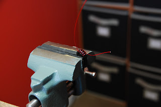 |
| I added Soft rubber to jaws of the vise |
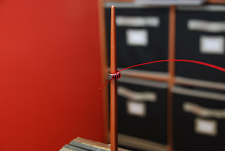 |
| Chopstick method |
I just want to share some of the ideas I tried during my trial and error periods of toroid winding. Also the process I go through from start to finish. As with most any kit I have worked with you are given a recommended length of wire to cut and I have found at least with the Elecraft kits the total wire given is always more than enough to wind all the toroids. Now comes the fun part the winding, there was three methods I tried. The first was putting the toroid core in a vise and winding the wire through the core. I found this to be somewhat awkward for me, some may find it works for them but I was opening and
closing the vise and moving the core around more than winding the toroid. Using the vise seemed to take a very long time. But having said that if your hand is not steady the vise is a very good alternative. The vise did great to just hold the toroid for the later step of stripping the leads...more about that later. The next idea that came across my path was the use of a chopstick, I included a picture of what I am taking about and we all know how a picture is worth a thousand words.
Using the chopstick I was able to form the turns of the wire nicely around the inside of the toroid. At the same time space the turns out so the toroid looked very balanced. I used this method with building my KX1 and as I wound each turn I inserted the chopstick and inspected the toroid. As I progressed to my next kit (Elecraft K2) I used the chopsticks for eating and not winding toroids. As it turned out this too was a method that just seem to complicate the winding process. As I gained confidence winding toroids I just put on my magnifying head set and wound them by hand!!! This proved to be the road for me in regards to gettin r done with the infamous toroid. See the link at the bottom of post to see how winding a toroid by hand is done. Once the toroid is wound you have to remove the coating of insulation on the wire. In this regard I read of sanding it off, using a lighter or flame of some type to bun it off or a hot solder blob. I tried the sandpaper method but I found it to be a little hard on the toroid windings and sometimes the sandpaper got to close to the turns of wire and removed some insulation there as well. I gave the open flame a go but found I was just heating up the wire and really did not have any control over removing the insulation and heat required to remove the insulation.
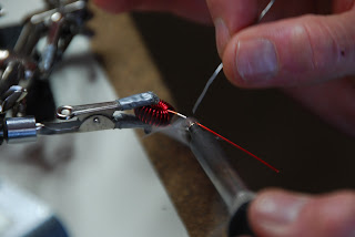 |
| Tinning leads |
SOME TIPS I FOUND HELPFUL
1. I always recount the number of turns just before the last turn is done. I find sometimes more turns are needed or I lost count and I have the correct turns already.
2. Just before placing the toroid into the circuit board one lead is cut shorter than the other. I find this makes placement of the leads into the board holes easier.
3. I ALWAYS use an ohm meter to check that my tinning job worked and the insulation is stripped.
4. Once the toroid is soldered in place before cutting the leads flush with the board I double check again with the ohm meter for continuity.
With practice I found the toroid winding can go smooth and it can be pleasurable as well.
 |
| 1 hour and 20 minutes of toroid wind. |
The vise method Once you are at the web page click on the upper left link "Toroid winding"
Mike Weir, VE9KK, is a regular contributor to AmateurRadio.com and writes from New Brunswick, Canada. Contact him at [email protected].
 Ham Radio Deluxe |
 W5SWL Electronics |
 Ham Radio Prep |
 KB3IFH QSL Cards  Hip Ham Shirts  HamRadioAuctions HamRadioAuctions Reliance Antennas Reliance Antennas Enigma Shop Enigma Shop |  morseDX  Ni4L Antennas  R&L Electronics R&L Electronics antennas.us antennas.us QRV QRV |
- Matt W1MST, Managing Editor
