 |
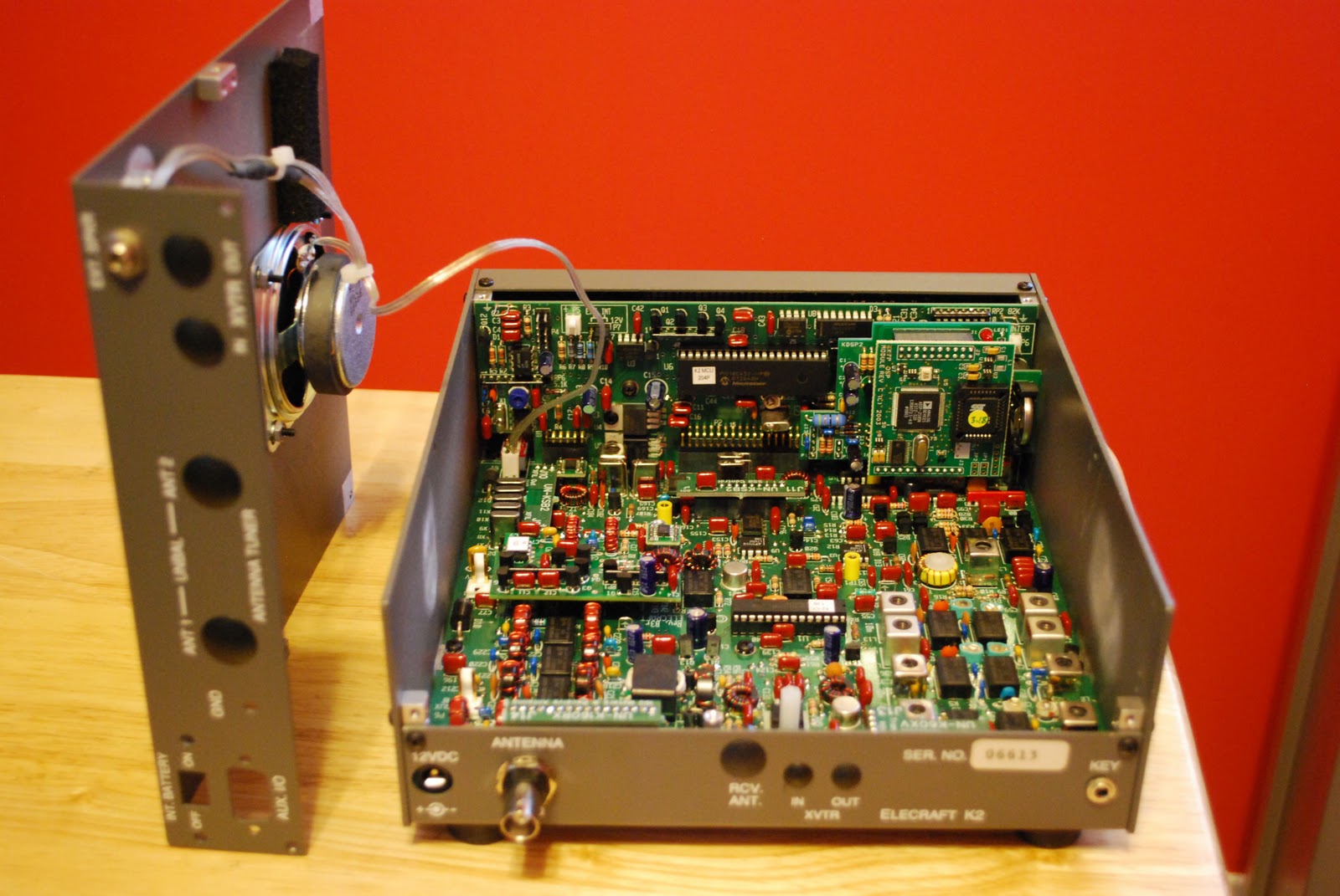
 Making the K2 portable……..
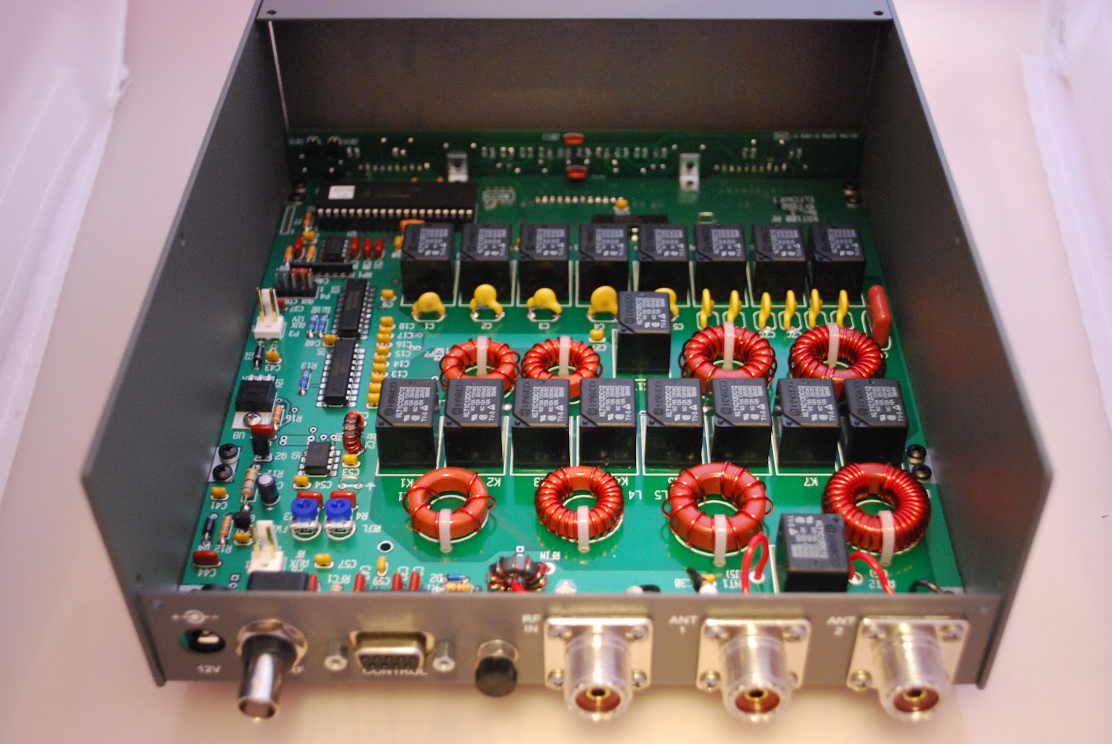 |
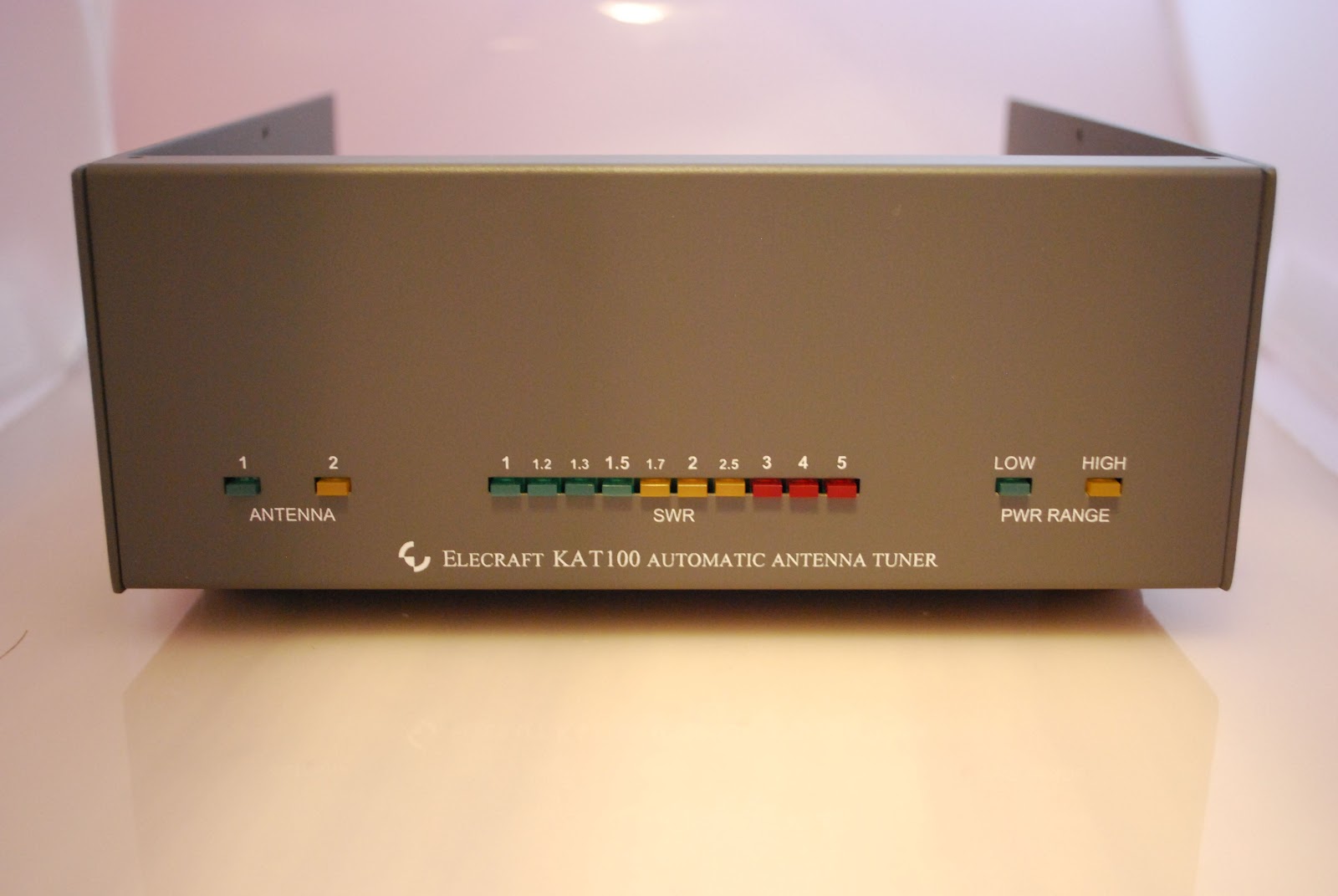
| KAT100 in new enclosure |
enclosure to house both the KAT100 and KPA100. I have completed the external antenna tuner. It went very smooth
 |
| Toroid lineup |
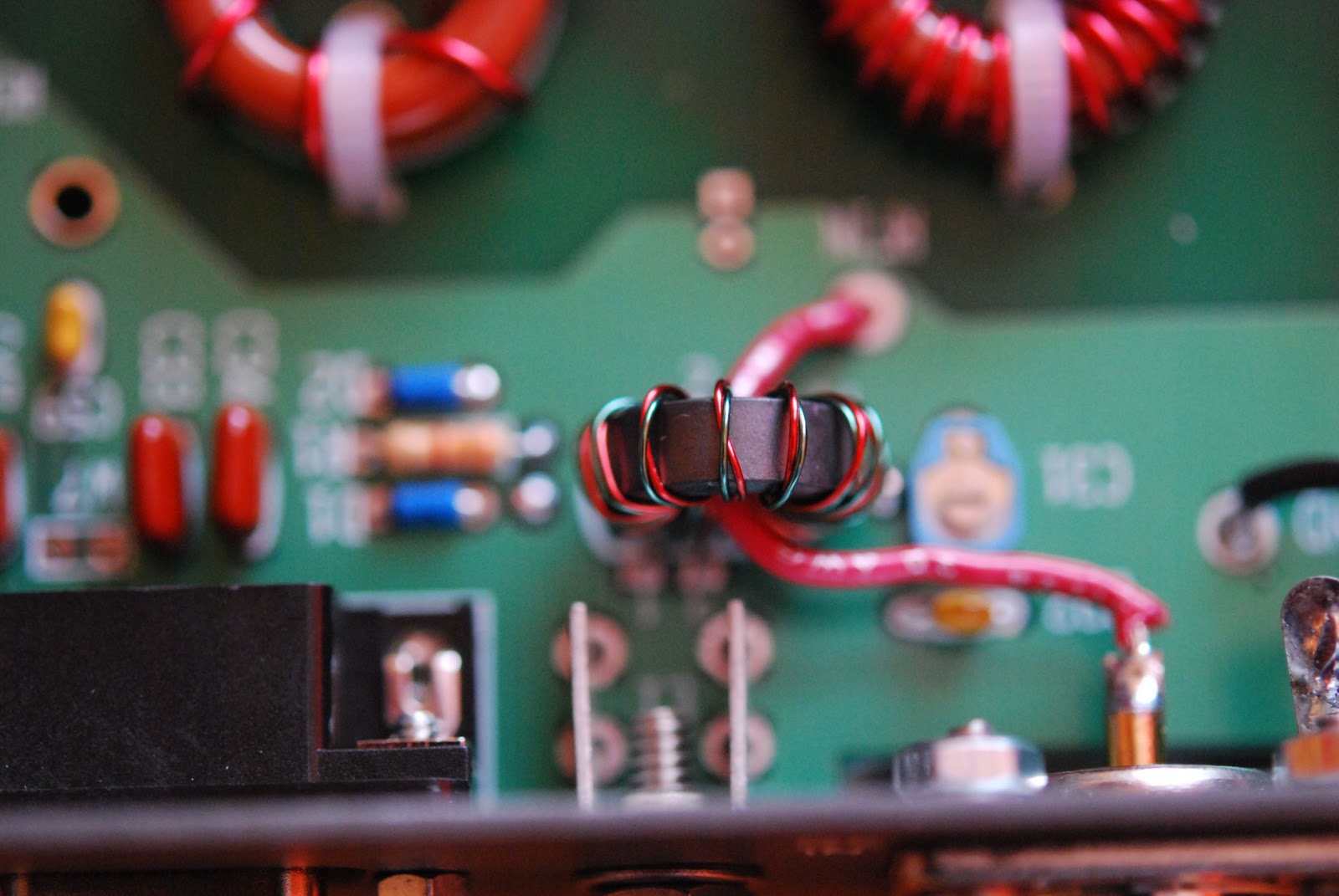 |
| Bifilar winding |
 |
 below from panel assembly |
If you are ever thinking of doing this project with your K2 below are some links that helped me out.
KK7P offers some very good advice along with some excellent pictures as well.
Wilcox Engineering also have some nice pictures of the unit and advice.
Mike Weir, VE9KK, is a regular contributor to AmateurRadio.com and writes from New Brunswick, Canada. Contact him at [email protected].
Results: 2011 Colorado FM Sprint
 The logs have been sent in, the scores tabulated and awards issued for the 2nd running of the Colorado FM Sprint. See my previous post, announcing the contest. The competition was
 tough significant weak not too bad rather slim and the following awards have been issued:
| Call sign | Category | Place |
| KDØLLG | Single Operator | 1st Place |
| KØJJW | Single Operator | 2nd Place |
| KØNR | Rover | 1st Place |
Come on out and play next year!
73, Bob K0NR
Bob Witte, KØNR, is a regular contributor to AmateurRadio.com and writes from Colorado, USA. Contact him at [email protected].
Poll: Best used HF rig for the money?

I’m planning on buying a small multi-mode HF rig for a relative who has recently become a ham. It’s been a very, very long time since I’ve bought a radio (used or otherwise). I’m polling the readership for opinions of the very best choice.
Ah, what do I mean by “best”?
Here are my criteria:
- Affordable
Browsing eBay and the other ham classified sites, there is quite a range of prices for used HF gear. I don’t really have a price in mind, but I am looking for a good value. As I can buy a new radio for about $600, I would say that the cost would have to be under $500 in the used market. - Reliable
The radio should probably be solid-state. - Portable
Should be able to be taken “backpack portable”
I would love to be in a position to spring for an Icom IC-7000, IC-718 or an Yaesu FT-817. They’re beautiful rigs, but I just don’t have the cash to spring for one.
What do you recommend? What’s the best value for your money?
Matt Thomas, W1MST, is the managing editor of AmateurRadio.com. Contact him at [email protected].
Radio Therapy

Ten metres has been really lively today. I made several contacts including some with the USA. The highlight was working Osama, 9K2OD in Kuwait City who came back to my first call (SSB) even though he had a bit of a pile-up! Perhaps my attic dipole and QTH are not so shabby after all!
It’s great to experience propagation conditions like this again and it cheers me up no end. Real radio therapy!
Julian Moss, G4ILO, is a regular contributor to AmateurRadio.com and writes from Cumbria, England. Contact him at [email protected].
Ham Radio Motorcycle Mobile [VIDEO]
A few months back I posted a story about getting a bicycle and looking up way to attach a radio to it to do some mobile work. While the summer has been busy and that project is on the side for the winter, I came across this video from KH1JH, of his Motorcycle mobile. Justin shows us how he mounted an HTX-202 from Radio Shack and is able to use it while on the road on his bike. A nice little setup if I do say so. Wish I could have a nice big hog to ride while doing 2 meters. That would be fun I bet! But I digress, here is Justin’s video. Enjoy!
73.
Rich also writes a Tech blog and posts stories every Tuesday and Thursday on Q103, Albany’s #1 Rock Station website, as well as Amateur Radio stories every Monday thru Friday on AmiZed Studios and hosts a podcast called The Kim & Rich Show with his fiance’ Kim Dunne.
Rich Gattie, KB2MOB, is a regular contributor to AmateurRadio.com and writes from New York, USA. Contact him at [email protected].
1 KW 4:1 Ruthroff (Voltage) Balun
Building baluns is just about the easiest construction project there is in ham radio. It pays to build your own, too. I’ve read reports from some disappointed hams out there who have paid good money for poor-quality baluns. The ones worth buying might cost you almost twice what you’ll pay to build your own. So I decided to build my own balun for the New Carolina Windom that I’m putting up. The total cost of materials was $40.  Balun")
The New Carolina Windom is essentially an off-center-fed (OCF) dipole. The big difference is in the balun that you use to feed the antenna. A current balun is the proper choice for an OCF dipole, since it effectively chokes common-mode current from standing on the feedline. But for a New Carolina Windom you want common-mode current on the feedline, since you deliberately use a portion of the feedline as a radiator (an additional RF choke is necessary to clamp off this common-mode current at a certain point on the feedline, but I’ll discuss that in a future post). Therefore, you use a voltage balun, not a current balun. The voltage balun allows some common-mode current to stand on the feedline.
Now, before I go any further I must warn you that I am not an electrical engineer. Baluns are a bit mysterious to me, but from the discussions I’ve read on the internet it seems I’m in good company. If you want to learn more about baluns, I recommend Jerry Sevick’s book, Understanding, Building, and Using Baluns and Ununs, available here.  This book has everything — easy-to-follow instructions for building different kinds of baluns, helpful tips from Sevick’s own experience, as well as some deep discussion of theory that should satisfy even a graduate student of electrical engineering. I followed his instructions for building a 4:1 Ruthroff (voltage) balun.
When building a balun there are several factors you must take into consideration. Do you want it to handle a full kilowatt, or are you willing to be forever limited to QRP? Now, I enjoy QRP (I love my little HW-8!), but I also want to have the option for QRO. Therefore, I chose to use not just one toroid, but two — and to use teflon-coated wire instead of the cheaper stuff you can get away with for QRP. I bought 100 feet of stranded (that’s right, stranded — it works fine!) 14 AWG silver-plated copper teflon-coated wire off of ebay for $34, shipped. That’s enough to build quite a few baluns!
When choosing the wire you’ll use in your balun, you must choose the wire size carefully. The diameter of the conductor and the distance between the center of each conductor determines the impedance of the pair you’re winding around the core. In a 4:1 balun, you want an impedance of 100 ohms. Since impedance around a core is only about 80% of that in free space, that means you want a guage and spacing that gives you 125 ohms. You can use the handy caculator for “Impedance of 2-Wire Transmission Line” at KW2P’s website, or you can figure it out yourself using this formula:
Zo = 276 * log 2(S/D)
S = distance between the centers of the two wires
D = diameter of the wire
Any unit of measurement works (inches, mm) as long as you use the same unit for both S and D.
You’ll notice that the spacing between the wires is critical. I used thin strips of strapping tape to tightly bind the wires together every couple of inches, and watched closely to make sure no gaps appeared as I wound the pair on the toroid.
Another thing you have to decide on is the permeability of the core. There’s lots of debate about this. I followed Sevick’s recommendation to use a permeability of 125 (ferrite mix 61). I purchased my two FT-240-61 cores from kitsandparts.com, stacked them, and taped them together using 3M Scotch glass-fiber strapping tape.
Now, what to put the thing in once you have it wound? The last time I built a balun, I put it in a project-box from Radio Shack. I won’t do that again — the plastic is just too thin. You want something strong enough to stand up to the stress put on the box by the eyebolts that you use to hang the balun and connect the antenna-wire to it. PVC pipe and end-caps are popular, but to house a balun this big it ends up being fairly expensive and downright heavy! I found the perfect solution at Menards for just under $7. It is a weatherproof enclosure made from PVC plastic and comes with a neoprene gasket to seal the cover to the box. I used neoprene washers for all the bolts and sealed all the entry-points (except for the binding posts and the bulkhead SO-239 coax connector) with silicone.
I spent a little time in the hardware store picking out the nuts and bolts for this thing. You want to make sure the bolts don’t work loose, so use lock-washers and lock-nuts where you can. I also used star-washers for each lug that I fastened to a bolt. Star washers have teeth in them that cut into the metal, ensuring a good connection. A fellow at the hardware store also cut me a small square of heavy plexiglass for 50 cents to use for securing the wound toroid inside the box.
When you have built your balun, you can test it by putting a pure-resistive load across the terminals and measuring the SWR across the spectrum you intend to use. For a 4:1 balun, that means a 200 ohm load (4*50=200). The SWR should be 1:1 across the spectrum. Here’s a video showing the test of the balun I built:
It looks good! I’m looking forward to using this balun. If you would like to build one of these and have any questions, ask away. I’ll give you whatever advice I can. Just remember — you’ll get what you pay for!


![]()
Todd Mitchell, NØIP, is a regular contributor to AmateurRadio.com and writes from Minnesota, USA. He can be contacted at [email protected].
A very unexpected QSO
On Friday evening I was just heading up to bed and I did my usual check on VHF/UHF to see what was happening. The FM box stopped on 145.7375. The normal station there is GB3AL but the station I could hear seemed to be in France – or at least the stations using the repeaters were. Signals were fairly weak but seemed to be fading up and down. I kept listening and the box identified; F1ZPL. A quick Google search and I was amazed. The repeater is in JN24WB – over 500 miles from me!
Tim Kirby, G4VXE, is a regular contributor to AmateurRadio.com and writes from Oxfordshire, England. Contact him at [email protected].
 Ham Radio Deluxe |
 W5SWL Electronics |
 Ham Radio Prep |
 KB3IFH QSL Cards  Hip Ham Shirts  HamRadioAuctions HamRadioAuctions Reliance Antennas Reliance Antennas Enigma Shop Enigma Shop |  morseDX  Ni4L Antennas  R&L Electronics R&L Electronics antennas.us antennas.us QRV QRV |
- Matt W1MST, Managing Editor
