 |
 Elecraft’s KIO2 project and kit building tips
 |
| Soldered nut |
 |
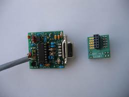
| DB9F installed |
connectors. After a few gentle tries and not successful I gave the board a good push and it did slip on and was a solid mating between the board and connector. At this step you may have to give a little elbow grease but the board will actually mate with the connector. Next I had to mount a 16.289 Mhz crystal care has to be taken as you can damage the crystal very easily with the heat from the soldering iron. The tip on the iron
 |
| Soldering on the can |
has to be changed back to the smaller tip enabling you to solder the crystal to the PC board. Once that is done a ground has to go from the top of the crystal (the can) to the PC board. To do this you must take the time to change the Weller tip again to the larger tip. Failing to do this and trying to do it the "fast" way may result in damage to the crystal or a poor solder job.....but most likely it will be both. Thus no time will actually had been saved. A discarded terminal lead is used for grounding. I start by forming the lead to fit properly. Then tin the top of the crystal add a little flux to the formed component lead. Put the lead on the top of the can of the crystal and add solder. Doing this way allows you to keep the soldering iron tip on the can for very short intervals. Now it's a simple case of mounting resistors and cap's after changing the Weller tip to the smaller tip. The inductors have been
 |
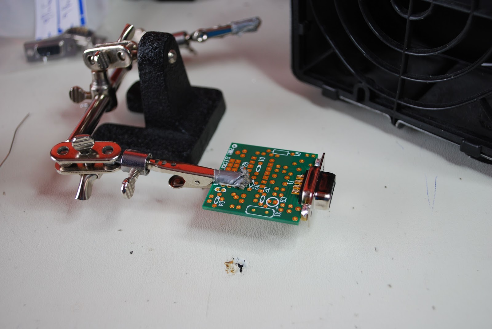
| Bending inductor leads |
 |
| Middle lead bent outward |
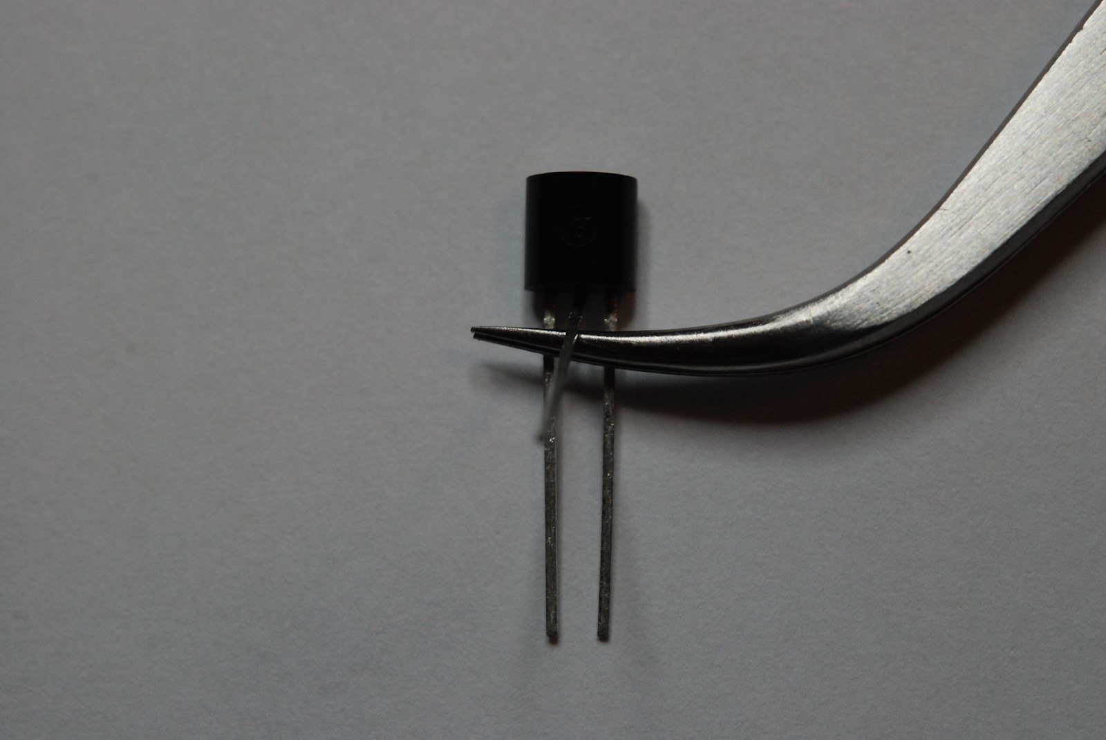 |
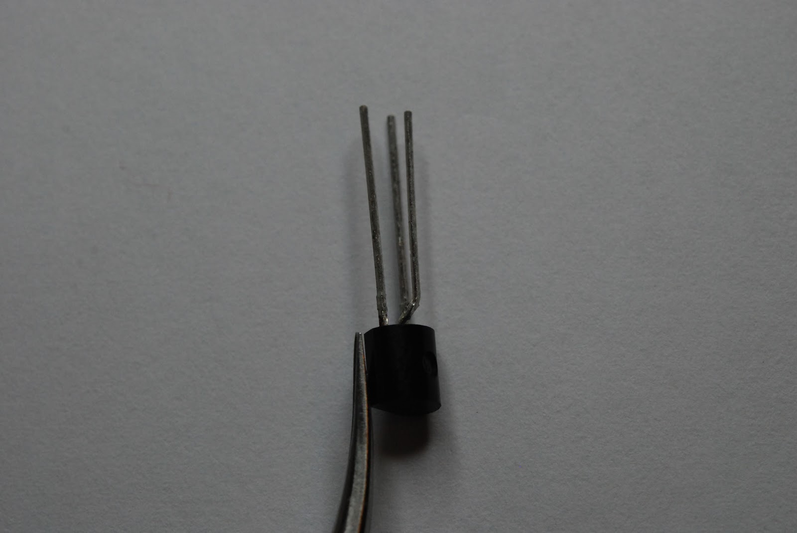
| Tweezers inserted then bend lead |
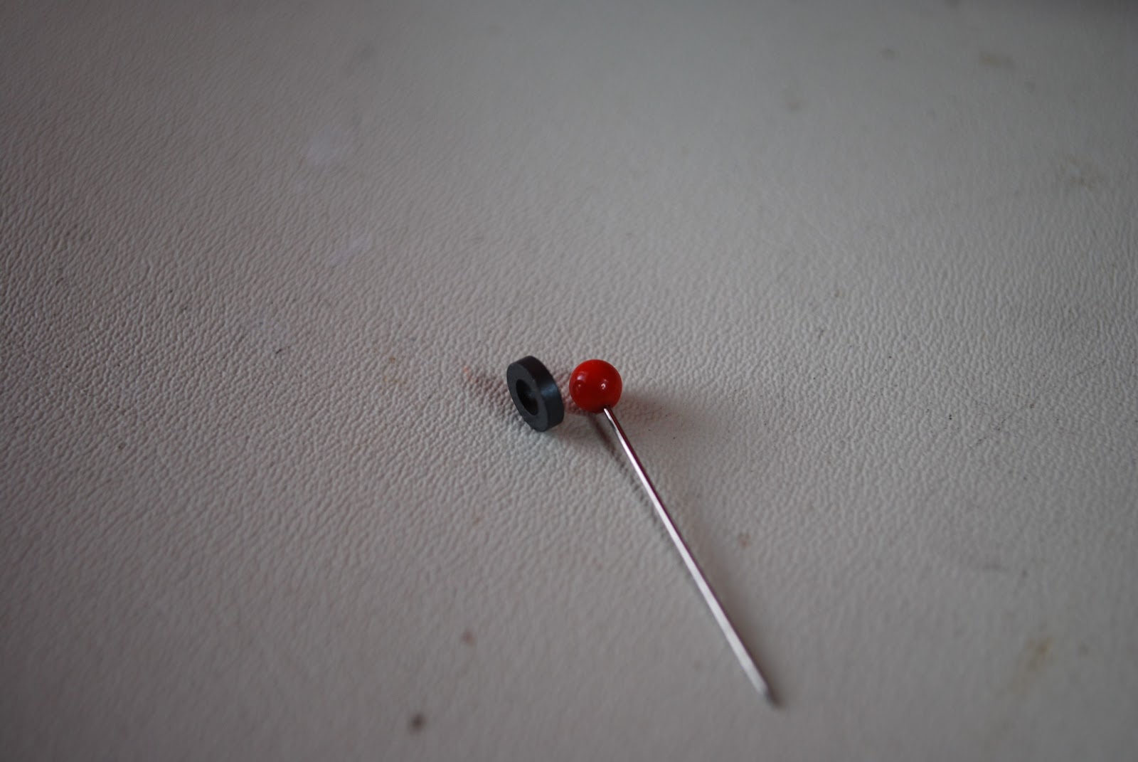 |
| Pin and toroid |
 |
| End result |
 |
| Keeping wide turns |
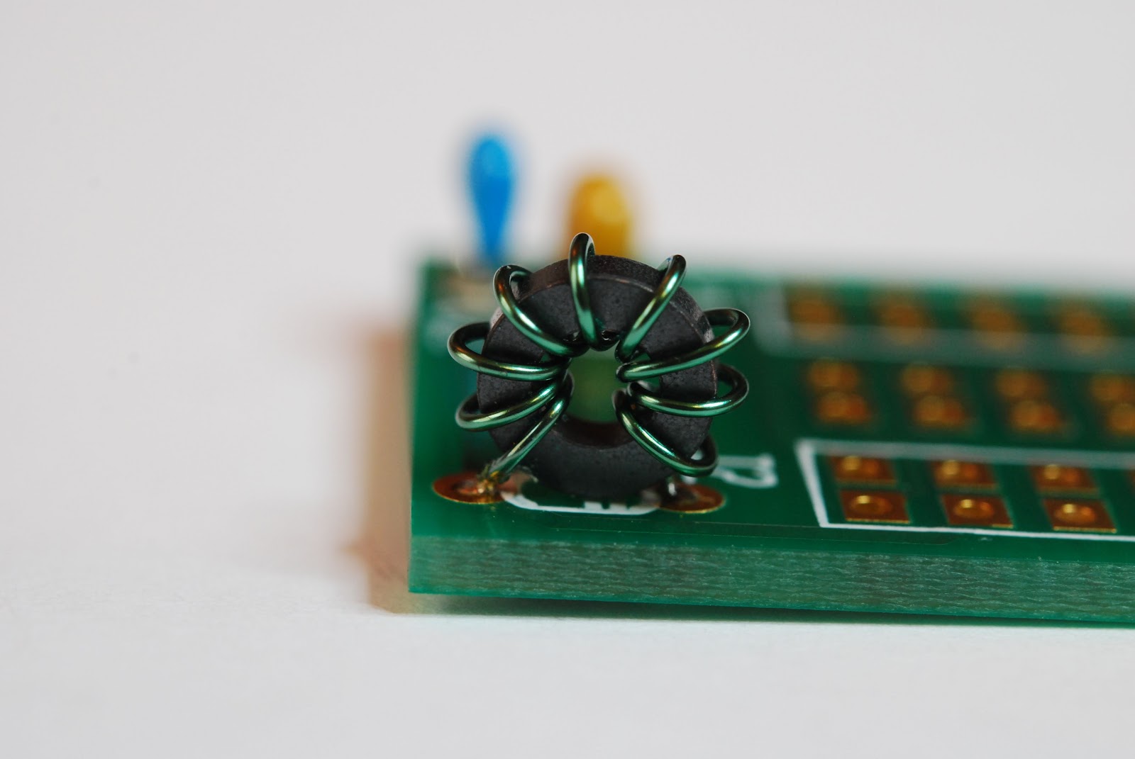 |
| New L1 Toroid |
 |
| Alligator clip vise |
 |
| installing in K2 |
Mike Weir, VE9KK, is a regular contributor to AmateurRadio.com and writes from New Brunswick, Canada. Contact him at [email protected].
This Spewed Out of the Internet #20
 There’s lots of information spewing forth from the interwebznet. Here are a few items of interest.
The amateur radio community is buzzing with excitement from the excellent propagation on the HF bands during the CQ Worldwide DX Contest last weekend. For example, see the radio-sport.net post or my post.
One of our local Boy Scouts passed his Technician exam on the Saturday before the contest, showed up in the FCC database on Friday and was working DX on 10 Meters on Saturday. He managed to snag some good ones, including Australia.
The ARRL is reporting that Logbook of the World is having trouble keeping up with the influx of radio logs. Although it would be nice if they could put a little more compute horsepower on the system, I think it is great that LoTW is seeing this kind of volume.
The Interstate Highway Rest Area Society is making a pitch to encourage hams to monitor 146.52 MHz when mobile. I usually try to do this and every once in a while I will stumble onto a great QSO that way. This group is also promoting ham radio activation of highway rest areas. Yes, really, it is not a hoax.
73, Bob K0NR
Bob Witte, KØNR, is a regular contributor to AmateurRadio.com and writes from Colorado, USA. Contact him at [email protected].
Making VHF go further: Morse can help!
The first weekend in November has always been one of my favourite VHF contests. There aren’t many purely CW contests on VHF these days, but the Marconi Memorial 144MHz is probably the best known. The nice thing is that all over Europe many of the top VHF contest stations and groups take part in the 24 hour event. Quite often at this time of year there is some tropo around and there’s always some meteor reflections too – so there are tantalising hints of contest stations some 1500 or 2000 km away!
These days I don’t treat the Marconi Memorial as a contest but as an exercise in DXing and to see what I can hear and work on 144MHz. This year despite indifferent conditions I was pleased to work TM0W in JN36 at just under 800km – it’s a path that works quite well from here as I see I have worked that station before. DF0MU in JO32 was a nice one too as well as a number of other closer French and Belgian stations. There were hints of more distant Italian and Czech stations, but nothing solid copied.
Although I wasn’t looking to work UK stations this weekend, I did get the impression that there were a few more people from the UK taking part which is good to hear
Tim Kirby, G4VXE, is a regular contributor to AmateurRadio.com and writes from Oxfordshire, England. Contact him at [email protected].
ICQ Podcast S04 E24 – National Ham Convention (06 November 2011)
Series Four Episode Twenty-Four of the ICQ Podcast has been released. News Stories include :-
- Radar sees through concrete walls
- Prospero to be reactivated
- RSGB Intruder Watch activity on 28MHz
- International digi-modes 10m net
- Rotuma High School Amateur Radio Station
- Radio/TV Martí 'anachronistic'
- Bletchley Park's Lost Heroes
- Global Simulated Emergency Test – November 2011
- VK100ARV roster begins
- Radio in Mayo
- Sydney radio hams help search for lost aircraft VH-MDX
Your feedback, North American Hambrief from Chris Matthieu (N7ICE) and Martin is joined by Chris Howard (2E0CTH) to discuss the National Radio Convention
Colin Butler, M6BOY, is the host of the ICQ Podcast, a weekly radio show about Amateur Radio. Contact him at [email protected].
DigiLite Update and Soapbox
Again, this is going to be a shorter version of my blogger ‘blog at http://w0fms.blogspot.com where I intend on having more random thoughts and technical detail than I post here! 🙂
I’ve purchased parts (in the US– all from Mouser for lowest overall cost except for the Analog Devices AD8346ARUZ Modulator IC– which they don’t carry) for the British Amateur Radio Club’s DigiLite “poor man’s” DVB-S SCPC modulator unit.

Almost complete BATC DigiLite DVB-S modulator board. All that is still needed is a MMIC amplifier be added after the QPSK modulator is properly adjusted with the external PLL Oscillator I am still awaiting from Israel.
The unit, as you may remember from my last post, uses an older analog Hauppage PVR-150, 250, 350, 500 and/or probably PVR-USB2 MPEG2 hardware encoder to set fixed constant bit rate (CBR) video and MP2 type CBR audio in a program stream format. This is translated to Transport Stream (TS) format for over the air transmission, Channel, EPG, and other needed DVB-S specific information is also multiplexed by the BATC software which is then sent to a DSPic33 that optionally adds the FEC (particularly at rate 1/2) and randomizes (to take out DC components because RF is inherently AC coupled!) the data– and then forms I/Q data with some pre-distortion with some tricks.. it’s filtered in a atypical way through an ANALOG LC Nyquist filter.. otherwise unfiltered PSK has infinite bandwidth! In commercial products a DSP typically would do this with a digital filter and a DAC. Finally the AD8346 does the I/Q phase shifting and that is the directly at frequency modulated DVB-S.
The LO is generated by a good e-bay find– a PLL L-band Oscillator that you can get from Ultram Tech in Israel custom programmed to one frequency. (I intend on reprogramming the unit with an Arduino [AVR ATMEGA part] board in the future– the chip’s dividers are programmed with SPI.) I have not received the board yet and didn’t want to disassemble and hack the 1152 MHz oscillator I previously bought about two years ago from Israel.
What the software and serializer firmware doesn’t do, thankfully, is care about the type of video that is in the MPEG-2 stream. I verified that tonight. The designers in the UK thought that NTSC would be fine.. and it seems to be.
Here is a video of the DigiLite “doing it’s thing” with rate 2222K video and 128K audio at a bandwidth of 3 MHz- 3MSym/S at 1/2 FEC QPSK. The video was set at NTSC D1 720×480 4:3 and I toyed with the settings until we were absolutely maxed out and were at close to zero null packets. Over the air, about 100K slower video might be a better choice. At 2112K, the null packets averaged 4.5%.. so somewhere in between these settings is about right for NTSC at 3MSym/s QPSK. This proves the digital part of the system out! We are close!
YouTube video of the BATC DigiLite running NTSC!
This is cool.. 1/2 the bandwidth and better quality than most Amateur TV. You’d think it was a no brainer for 70cm to replace 6-8 MHz AM TV? Well it is.. but in my not so humble opinion it’s not legal to run.
—SOAPBOX—
Part 97 defines that a digital phone or image (important definition) signal is legal if it uses the same or less bandwidth than the equivalent analog signal.
DVB-S and other digital standards definitely do. Unfortunately, from commercial license grants researched, I note that ATSC is C7W emission type and DVB-S/S2/C/T is G7W. Image is defined to EXCLUDE “7W” emissions. C7W and G7W are specifically defined as “multiplexed data” in another part of the rules– actually in reference to RTTY in the typical early 1980’s wording of those rules. So because DVB-S is “data” by part 97 definition, the 56K baud/100KHz BW rule applies at 70cm. In my not-so-humble-opinion it is not legal to run DVB-S nor ATSC (?!?) at 70cm because of these antiquated and wrong rules. But it is legal at 33cm and above as wideband data.
There are several who disagree with me on this. But for their definition to be valid technically by the Part 97 rules as they stand ATSC and or DVB-S would have to be G2F (DVB-S) or C2F (ATSC). By the Emissions Designator system that would also imply no audio channel. F2F is what SSTV is and I believe the “image” definition for FM/PM/PSK was specifically written with HF SSTV in mind! NO COMMERCIAL license grant (I found) has it defined that way! I can’t run 70cm DVB-S because I interpret the rules as above. Anyone who disagrees with me and wants to run it is fine with me. Wish you the best and I’m all for you! Likely the FCC nor the ARRL would do a thing to you as they shouldn’t!
What this really means is that the digital rules in US ham radio need fixing in a big way! We need to get rid of all the protectionist crap and realize that for many modes, the handwriting is on the wall for analog. The way the current rules are written in Part 97 makes most new digital modes second-class citizens on the bands. Bogus and Sad IMHO in almost-2012.
— /SOAPBOX —
Fred Spinner, WØFMS, is a regular contributor to AmateurRadio.com and writes from Iowa, USA. Contact him at [email protected].
The start of the contest season
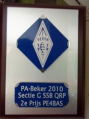 |
| Plaque I received yesterday |
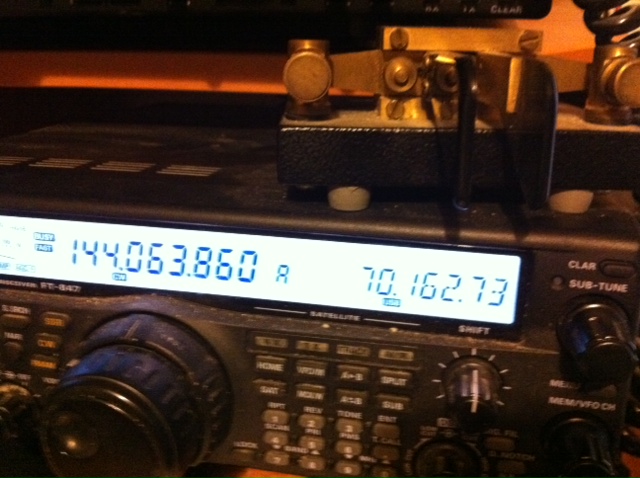
The CQWW SSB is as always the beginning of the small contest season for me. I did a lot of contests in the past but since family life keeps me busy I choose to participate only the important ones. Some of those are only important for me as a Dutchman like the PA-beker contest, Friese elfstedentocht contest and the PACC. I placed myself 2nd in the PA-beker and 4th in the Friese 11 steden last year and this month I’ll try to improve myself, I guess it’s going to get difficult. Next thing to do is to set up the horizontal loop again, after that I will see if there is time and room for any improvements on the station. Anyway, one thing is for shure I really want to have fun that’s the most important thing. First contest coming now is the PA-beker contest which is purely a contest inside the Netherlands, I will participate again in the QRP section with my FT-817. Only this time I will use N1MM as contestlogger instead of the PA0FLE contestlogger I used in the past. Hopefully it will help to beat my score of last year.
Last years declare:
Place / Call / Region / QSO / Multiplier / Score
1 | PA1AT | 19 | 118 | 61 | 7198 |
2 | PE4BAS | 19 | 73 | 48 | 3504 |
3 | PA3DAT | 49 | 69 | 47 | 3243 |
That means if I want to be at first place I need approx 120 QSO and 60 multipliers. Looks easy, but I can tell you it’s difficult to make so much QSOs in 2,5 hours especially when QRP.
Bas, PE4BAS, is a regular contributor to AmateurRadio.com and writes from Groningen, Netherlands. Contact him at [email protected].
 Ham Radio Deluxe |
 W5SWL Electronics |
 Ham Radio Prep |
 KB3IFH QSL Cards  Hip Ham Shirts  HamRadioAuctions HamRadioAuctions Reliance Antennas Reliance Antennas Enigma Shop Enigma Shop |  morseDX  Ni4L Antennas  R&L Electronics R&L Electronics antennas.us antennas.us QRV QRV |
- Matt W1MST, Managing Editor
