 |
 First spin of the propeller
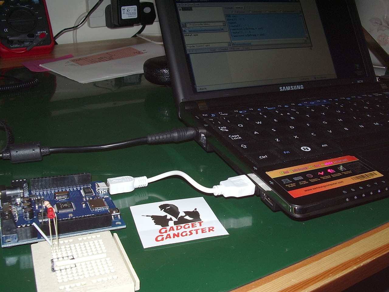
A new toy dropped through the letterbox today. It is a Gadget Gangster Propeller Platform USB demo board for experimenting with the Parallax Propeller microcontroller. If you haven’t heard of the Parallax Propeller before then it is an inexpensive micro chip that contains eight processors called cogs (as in gear wheels) that can run independently in parallel. It’s quite a bit different from the Microchip PIC or Atmel devices which have a single processor architecture similar to an ordinary computer.
I sent off for the board just after Christmas, after reading about it in Eldon Brown WA0UWH’s blog. Eldon posted code showing how the board could be used as a QRSS beacon. I was quite excited by the idea of a device that with simple programs even I could understand could be made to emit RF.
I sent off for the board on 27th December choosing the low cost untracked USPS air mail shipping option and it arrived today, 4 January – much quicker than expected. What’s more, there were no nasty customs charges! Gadget Gangster still has a special offer of $10 off for the board, so if you fancy getting one of these to play with now is the time to do something about it.
I was very impressed at the speed with which Gadget Gangster processed my order. What you get, though, is just the board. You will need to provide a power supply (7.5 – 12V with a 2.1mm barrel connector, centre positive) and a USB cable with a mini-USB jack at one end. These seem to breed in my junk box so that was not a problem. You will also find useful a small breadboard and some hookup wire to attach components to the board and test your programs.
I installed the Propeller Tool – a free download from the Parallax website, connected the board to my Samsung NC10 netbook. I then tried the Blinky Light tutorial from the Gadget Gangster site. It didn’t work – until I connected the LED the correct way round (stupid newbie error!)
Over the next few days I’ll be working through the tutorials to get the hang of the system. Then I’ll take a look at Eldon’s QRSS beacon code and adapt it to send my own call. I’d like to make a WSPR beacon. I don’t know yet if that will be possible, but I’m looking forward to playing with this Propeller chip and using it in some radio-related project. Watch this space!
Julian Moss, G4ILO, is a regular contributor to AmateurRadio.com and writes from Cumbria, England. Contact him at [email protected].
Amateur Radio Kid’s Day is January 8th
Now is the time all over the world where Hams open up their stations to let kids in to experience Ham Radio. January 8th is the magical day and it’s sure to be fun for all involved. For those new to the hobby, it’s not another contest, but just a fun time.

Photo Couretsy of ARRL.org
The American Radio Relay League has a website dedicated to Kid’s Day, as does the IARU Region 1. It’s all about having Kid’s participate by calling CQ Kid’s Day and exchanging Name, age, location and favorite color. And you’re encouraged to work stations again when the operator changes. Operations take place at 1800 UTC through 2359 UTC. The ARRL shows that operation is on the following frequencies:
10 Meters: 28.350 to 28.400 MHz
12 Meters: 24.960 to 24.980 MHz
15 Meters: 21.360 to 21.400 MHz
17 Meters: 18.140 to 18.145 MHz
20 Meters: 14.270 to 14.300 MHz
40 Meters: 7.270 to 7.290 MHz
80 Meters: 3.740 to 3.940 MHzYou can also use your favorite favorite repeater (with permission of the repeater’s sponsor). Be sure to observe third-party restrictions when making DX QSOs.
The ARRL has a colorful certificate that all kids are eligible to receive just by participating. But beware, some kids can be mic shy. So encourage them in a fun way.And remember to also post your photos and stories for all to see. If your club doesn’t have a Facebook page, this may be the best time to start one.
73.
[adrotate group=”2″]
Rich Gattie, KB2MOB, is a regular contributor to AmateurRadio.com and writes from New York, USA. Contact him at [email protected].
Fun on 10m and a call from the past
I checked WSPRnet.org this morning and found quite a lot of activity on 10m so I fired up the K2 and joined the fun with a 1 watt signal. By late afternoon I’d had well over 40 unique call / spotter combinations including good reports from FR1, VK6, VE and the USA.
At lunch time I switched to the K3 (which has a mic attached) to make some SSB QSOs. This was not especially productive. Several US stations running high power to multi-element beams were huge signals over here, but they had huge numbers of European stations calling them and my 100W to an attic dipole had trouble being heard over them. Actually I was only using 80W as I found going up to 100W on 10m caused my homebrew digimodes interface to disconnect itself from the computer. When I was heard, I received good reports from N2JF and NU1O. Perhaps I’d have made more contacts if I’d called CQ.
During my WSPR session I saw that my signal had been spotted by a callsign that rang a bell: G4HBA. A quick look at qrz.com confirmed that my memory was correct: G4HBA was Roger who had also been G8KRT some 35 years ago. During the long hot summer of 1976 when I was G8ILO and only allowed to use 2m and up I was home from university and using an Icom IC-202. Roger was portable from near his place of work in south east Essex and working strings of Continental stations during the endless tropo openings. As I had no antenna at the parental QTH I drove out to find him and on several days I joined Roger and made some contacts under my own call.
One evening I drove out to the site and Roger was not there, so I went to the top of the hill and started operating using my IC-202 and a small beam I made that was supported by the car door. After about half an hour it was getting dark and I noticed torches moving about and closing in on the car. Suddenly I was surrounded by police in uniform! Apparently my car interior light had been spotted from several miles away (as I was on top of a hill) and as I was right next to a radar station someone had wondered what I was up to. That was the end of my operating from that particular site, but I will always remember the amazing VHF propagation of that summer and regret that I never experience such conditions on 2m here.
Julian Moss, G4ILO, is a regular contributor to AmateurRadio.com and writes from Cumbria, England. Contact him at [email protected].
N7TFP Demonstrates How to Set SSB Gain
Happy New Year to all! I’m back after a week’s vacation for the holidays and feeling very rested. Tyler, N7TFP on the other hand, has been busy, busy, busy. I don’t know about the holidays, but the videos he’s been cranking out are great! Here’s another one for you!I have been saying this with the last couple videos that getting back to basics are great for the veterans on the air, and these are great tutorials for those just joining or recently joined the hobby. In this one, Tyler shows how to set the proper mic gain on your SSB tranceiver. Without any more fanfare, heeeeeeeere’s TYLER!
73.
[adrotate group=”2″]
Rich Gattie, KB2MOB, is a regular contributor to AmateurRadio.com and writes from New York, USA. Contact him at [email protected].
Minimum-Loss Matching Pad
In my last post I promised to write about the minimum-loss matching pad that I’m using to couple my signal generator to the device I’m testing. The source impedance of the generator is 600 ohms and the output is intended to be terminated in a 600 ohm load, but the device I’m testing is only 228 ohms. The way to match this with the lowest loss is with a transformer, but it is inconvenient and unnecessary to come up with a transformer for every mismatch this piece of test-equipment will face.
Thanks to advice from the ham who is guiding me in this project, I’m using a minimum-loss matching pad, also known as an “L-pad,” to match these two impedances. (I’d tell you who this fine fellow is, but to keep you in suspense about my project I’ll wait until my final write-up. If I name him now, the cat will be out of the bag!) This quick, cheap, and easy match requires only two resistors:

Courtesy of http://www.microwaves101.com/encyclopedia/attenuatorL-pad.cfm#minloss
To calculate the value of the resistors and to calculate the loss of the matching pad, use these formulas (A spreadsheet that uses these formulas is available through this webpage.):

In my case R1=472, R2=290, and the loss is -9.25 dB. That loss is pretty significant, but it is acceptable for this application. Remember this is a minimum-loss matching pad, not a no-loss matching pad. Using what resistors I had on hand to come as close as I could to the required values, I soldered this pad on a generic PC board from Radio Shack that I cut in half using my Dremel tool with a cutting wheel:


For more on this topic, I commend to you this webpage on “Impedance and Impedance Matching.”


![]()
Todd Mitchell, NØIP, is a regular contributor to AmateurRadio.com and writes from Minnesota, USA. He can be contacted at [email protected].
Making QRP to QRP contacts…..
 |
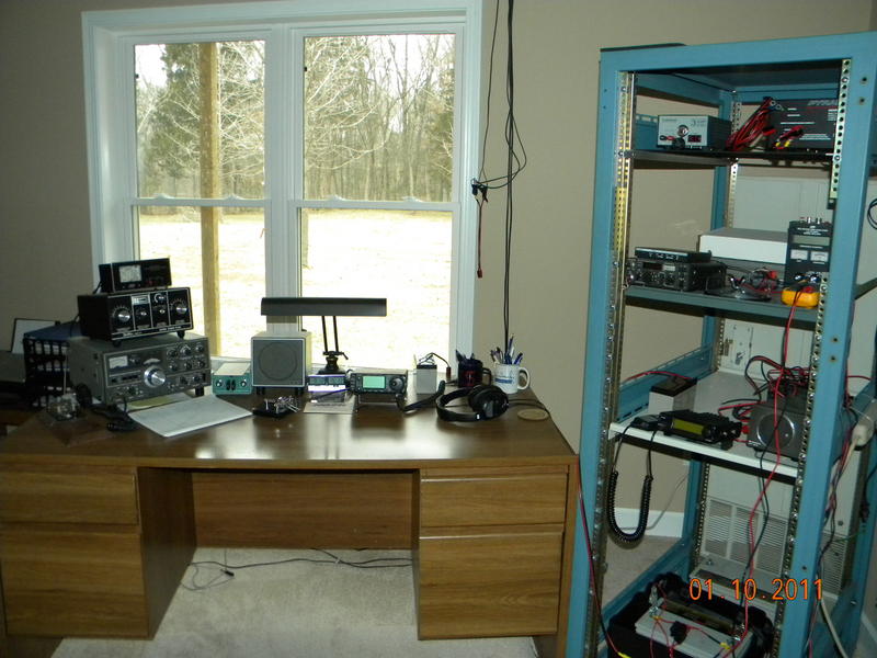
| VE1BA's shack |
I then called CQ on 14.060 and Mike N0ZH came back to me with a 559 signal. He gave the the same signal report. It was not long before Mike started to fade in and out and very hard to read. So my QSO to Missouri came to a fast end. For this QSO the K3 was at 1 watt with a better miles per watt at 694 miles. I did hear KF5HGL calling CQ I started returning his CQ at 500mW's and climbed all the way up to 5 watts and he was not able to copying me. So either conditions were changing or it was not time for me to make a QSO into New Mexico.
 |
| N0ZH's shack |
Mike Weir, VE9KK, is a regular contributor to AmateurRadio.com and writes from New Brunswick, Canada. Contact him at [email protected].
More Summits On The Air (SOTA) Info
 I recently wrote about the Summits On The Air (SOTA) program gaining traction here in Colorado. Catching up on some of my podcast listening, I came across Jerry KD0BIK’s Practical Amateur Radio Podcast (PARP) on the topic of SOTA. It turns out that Jerry has gotten hooked on the SOTA program and has been out activating some of the Colorado peaks in December.
Operating a ham radio on top of a mountain during winter may seem like the act of a person with only one oar in the water (or shall we say one half of a dipole in the air?). But actually, we’ve had quite a few days of favorable weather that have been begging us to get outdoors in December. Still, I am on guard for an activation by Jerry in the middle of a blizzard, as he seems a bit smitten by this SOTA thing.
Episode 49 of PARP introduces the SOTA concept near the end of the episode, which is followed by a deeper SOTA discussion in Episode 50. These two episodes run about 25 minutes each, so take some time out to give them a listen.
73, Bob K0NR
Bob Witte, KØNR, is a regular contributor to AmateurRadio.com and writes from Colorado, USA. Contact him at [email protected].
 Ham Radio Deluxe |
 W5SWL Electronics |
 Ham Radio Prep |
 KB3IFH QSL Cards  Hip Ham Shirts  HamRadioAuctions HamRadioAuctions Reliance Antennas Reliance Antennas Enigma Shop Enigma Shop |  morseDX  Ni4L Antennas  R&L Electronics R&L Electronics antennas.us antennas.us QRV QRV |
- Matt W1MST, Managing Editor
