 |
 Heathkit’s first amateur transmitter – Heathkit AT-1
The Heathkit AT-1 represents the commercial embodiment of the simple Master Oscillator Power Amplifier (MOPA) transmitter using a crystal controlled 6AG7 oscillator plus a 6L6 final output tube.
Although it was possible to design and build a simpler transmitter, the goals of output power and stability could become mutually exclusive when trying to operate with only one tube. For a novice class license holder of 1951 the Heathkit AT-1 represented a solid performing rig that would be relatively easy to construct and operate.
The Novice remained the primary entry license until the Morse code requirement was eliminated for Technician licenses in 1990. On HF it permitted code transmissions only, with a maximum power of 75 watts, (input to the transmitter’s final amplifier stage) on limited segments of the 80, 40 and 15 meter bands.
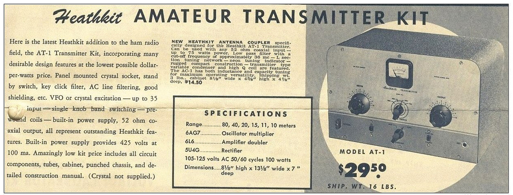 |
| For $29.50 and the loan of a few tools you could get some use out of that new novice license |
The earlier MOPA circuit from the ARRL handbook of 1941 below shows a layout remarkably similar to the circuit of the AT-1 although it is designed for plug in coils rather than the band-switching arrangement of the later Heathkit transmitter.
| MOPA transmitter using a 6L6 and an 807 as the power amplifier (ARRL Handbook 1941) |
For a little added complexity MOPA transmitters generally offered better stability of frequency and keying waveform than single tube crystal controlled or self exited rigs. The straight forward design of the AT-1 should have looked familiar to novice class hams after studying the ARRL handbook or other radio publications.
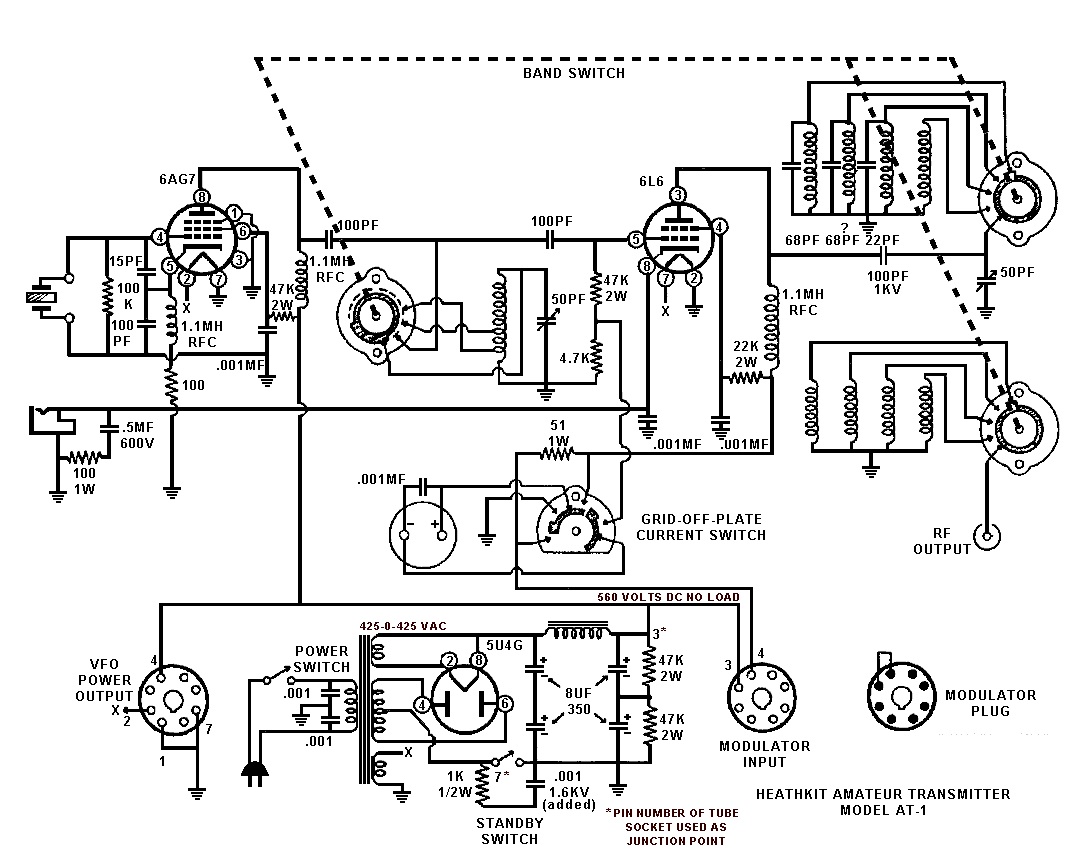 |
| Heathkit AT-1 Circuit diagram showing band-switching arrangement and link coupled output |
Once the novice had upgraded his license the AT-1 could be expanded by the addition of the Heathkit VF-1 variable frequency oscillator to allow transmission on any frequency within the allowed band.
 |
| The Heathkit VF-1 Variable Frequency Oscillator |
The VF-1 covered 160-80-40-20-15-11-10 meters and used an OA2 voltage regulator tube to provide a stable voltage for the oscillator. Ceramic coil forms, solid construction and high quality components were used to help increase stability.
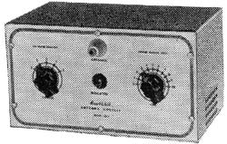 |
| The Heathkit AC-1 Antenna Coupler. Designed to attach to a single wire by the insulated post on the front panel. |
 |
| Heathkit AC-1 Antenna Coupler circuit diagram |
Although Heathkit did not produce a AM modulator for the AC-1 there is provision for modulator connection on the rear panel. The earlier ARRL manuals have several suitable circuits for modulators that would work with the AC-1. Most functioned by driving a modulation transformer with the output from an audio power amplifier. The secondary of the modulation transformer would be carrying the DC plate supply for the power amplifier tube plus or minus the instantaneous voltage of the audio waveform. By changing the plate voltage to the final amplifier tube the radio frequency output would be controlled by the amplified audio frequency resulting in amplitude modulation.
Owen Morgan, KF5CZO, is a regular contributor to AmateurRadio.com and writes from Texas, USA. Contact him at [email protected].
So what’s been going on………
 |
| The repaired key ready for action |
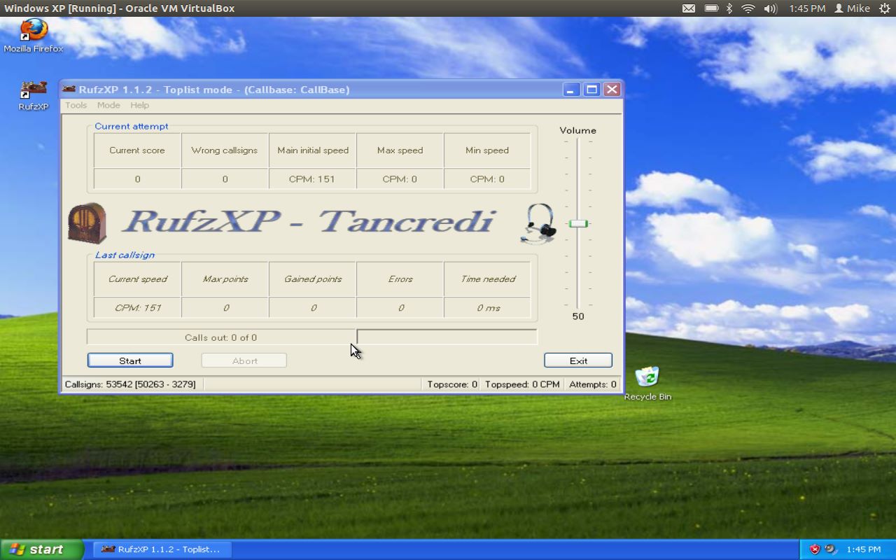 |
| RufzXP happy again |
took the jump and downloaded Virtualbox onto my Ubuntu laptop and installed WinXP. Virtualbox is a great program that allows you to run other operating systems within a "virtual computer" it creates. I now have Windows XP running on my machine and was able to install Netframe 2.0 and RufzXP...all are getting along just fine now.
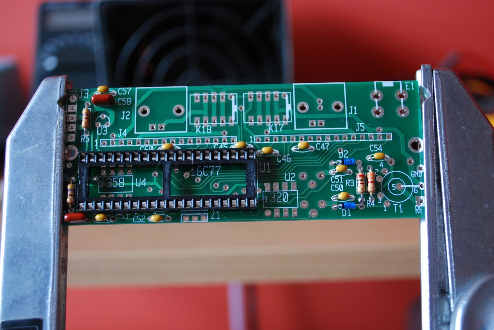 |
| The KAT2 which also has a "cat" hair |
Mike Weir, VE9KK, is a regular contributor to AmateurRadio.com and writes from New Brunswick, Canada. Contact him at [email protected].
Propeller crash
Yesterday I had another of those days that nearly made me decide to hang up my soldering iron for good. Some readers may have spotted the despondent blog post I made before I deleted it.
I assembled the Propeller LCD UI module. It went together easily and I had no trouble with the soldering using a magnifying lens (a strong pair of clip-on reading glasses clipped on to my normal reading spectacles) and resting my soldering hand on the desk to stop the shakes. But Murphy was not going to let me get off that easily.
Preparing to test the UI board I realized that I had skipped a page of the instructions and had not soldered a connector to the LCD daughter board. I thought that a connector for the main board (a male 8 x 2 box header) had been omitted from the kit so I had installed one of my own. When I picked up the daughter board I saw the two rows of 8 holes and without thinking installed the 8 x 2 plain header that came with the kit. Also male. When I realized my mistake bad words were said. In all my years of kit building I have never before done anything quite so stupid.
I recalled Don Wilhelm W3FPR’s advice to K2 builders who install multi-pin connectors on the wrong side of the board to sacrifice the connector and not try to remove it intact. This I eventually did with Olga’s help. She suggested I place the soldering iron body along the row of soldered joints to melt all of them so the connector would fall out. That didn’t work, but it did soften the plastic part of the connector allowing it to be pulled away. I could then remove each pin one at a time and clean up the through holes using one of Olga’s sewing needles. Finally I was able to install the four 1 x 4 female headers that had presumably been supplied with the kit as a replacement for an 8 x 2 female that was really needed.
After all that stress (both to me and the board) I was relieved that when I plugged it in to the Propeller board and ran the demo program the UI module worked. But my happiness was short-lived. After I tried some modifications to the program I found that it seeemed to be crashing. The program would start at switch-on but would eventually hand up and not respond to the buttons. Sometimes garbage appeared on the LCD. The time before this happened got shorter with each attempt until sometimes the Propeller wouldn’t even respond to the reset button. I restored the original program in case my changes were to blame, but the device was still crashing.
Next I re-heated all the solder joints I had made, though they all looked OK. On reassembly the Propeller still crashed. Thoroughly despondent by this point I typed a post describing what happened in the hope that someone would offer to come to my rescue (thanks to those who did.)
After a rest it occurred to me that I had crashed the Propeller by dropping the board a centimetre or so on to the desk. There was probably still a bad connection somewhere. I re-soldered all the joints, including all the ones on the main Propeller board. That had been ready assembled. I guess that the manufacturer had used lead-free solder because I couldn’t melt the joints until I applied a bit of my own leaded solder to each one. Then all the joints looked nice and shiny.
After that treatment everything worked and up until now, cross fingers and touch wood, has continued to do so. So it seems that a poor soldered joint in the manufactured board was the cause of my problem! Thank you, Murphy, but I don’t need your help. We do this for fun, do we?
Julian Moss, G4ILO, is a regular contributor to AmateurRadio.com and writes from Cumbria, England. Contact him at [email protected].
WD40
Two days ago we still had 10 degrees Celsius and rain. Sunday saw 24 degrees and sun. So what better to do than cleaning the Spiderbeam pole. WD40 sure made it shine again.

Hans "Fong" van den Boogert, BX2ABT, is a regular contributor to AmateurRadio.com and writes from Taiwan. Contact him at [email protected].
ICQ Podcast S05 E04 – DVAP – Digital Voice Access Point (12 February 2012)
Series Five Episode Four of the ICQ Podcast has been released. News Stories include :-
- SumbandilaSat beyond repair
- Sweden loses 13cm amateur radio band
- FCC sets date for medical devices on 70 cm
- RSGB PLA/PLT Devices Announcement
- BATC Convention 2012
- FISTS marks a milestone
- New rules for 5 MHz (60 meters)
- VOA anniversary spurs museum effort
- Morse code not on the way out
- UK Propagation charts for February 2012
- Record set at Winter Hill
Your feedback, Ed Durrant provides his latest Australian report and Martin reviews a DVAP (Digital Voice Access Point).
Colin Butler, M6BOY, is the host of the ICQ Podcast, a weekly radio show about Amateur Radio. Contact him at [email protected].
South Texas Balloon Launch Team launches balloon aimed at China
My daughter and I made the short trip to the No Label Brewing Company in Katy TX to watch the South Texas Balloon Launch Team launch a helium balloon aimed at Nanjing China. Thanks to Tom AE5QB for letting us know about this event!
To track the balloon in real time go to : http://aprs.fi/?call=a%2FKT5TK-11&_s=mb
From the press release of the South Texas Balloon Launch Team:
The South Texas Balloon Launch Team is pleased to announce the upcoming launch of its twenty-eighth, helium-filled, unmanned balloon in twenty one years. The purpose of this flight is to establish a world record for distance by floating a balloon from Katy, Texas to Nanjing, China.
The balloon will be released at approximately 3 P.M. CST on Saturday, February 11, 2012. The site of the launch is at the western end of the No Label Brewery complex at 5373 First St., Katy Texas, near the old rice grain silos.
The public is invited to this free event, with a special invitation to science students and teachers. Free helium-filled balloons will be available to the first 100 students. Sorry, no pets allowed in the balloon area.
The balloon payload package weighs only about five ounces (150 grams) and contains a high altitude GPS tracking system and a VHF amateur radio transmitter. To conserve weight and battery life, no camera equipment will be on board. The maximum altitude is expected to be above 100,000 feet, with horizontal speeds between 100 and 150 MPH. The balloon size will increase from about five feet to about 39 feet at maximum elevation. Recovery of the payload package is not expected.
Individuals may follow the balloon’s progress on the Internet by logging onto APRS, filling in the “track callsign” field with “kt5tk-11”, and change the “show last” to 24 hours.
The South Texas Balloon Launch Team is composed of about twenty active amateur radio “Ham” operators from a variety of occupations who donate their time and expertise.
We appreciate the continued support by No Label Brewing Company for our amateur radio projects.
Owen Morgan, KF5CZO, is a regular contributor to AmateurRadio.com and writes from Texas, USA. Contact him at [email protected].
Project Abandoned
I am abandoning the Propeller Beacon project. Sadly I am forced to accept that in my current state of health the construction of electronics is beyond my ability. All of my recent attempts have resulted in one problem or another due to stupid mistakes that I would never have made when I was well. It’s time to put the soldering iron away.
Yesterday I made up the LCD UI board for the Propeller. It seemed to go well. The instructions were good and I didn’t have any difficulty with the soldering. I thought I had finished, then realized that I had skipped a page and hadn’t soldered a connector to the LCD daughter board. That’s when I made a stupid mistake. I had soldered a male 2×8 header to the main board. Then I went and soldered another male header to the LCD board. And then I wondered what the four 1×4 female headers left over were for. Obviously they were meant to be soldered in two rows of two to make a 2×8 female header to mate with the male I originally installed. Bad words were said.
With the help of Olga I managed to get the header off. We heated all the pins using the soldering iron body which softened the plastic base until it could be pulled off. Then I removed the pins one at a time. I cleaned the holes using one of Olga’s sewing needles and installed the female headers I should have put in. All seemed well and no harm appeared to have been done apart from to my nerves and temper.
I powered up the Propeller board and loaded the LCD UI demo program. It seemed to work. I changed a few things in the program as an experiment. Then I found that the Propeller stopped responding to the buttons. After anything from a minute or so to a couple of seconds the program eventually crashed. Sometimes it would respond to a press of the reset button, sometimes it needed a power on/off. I restored the original unmodified demo program in case it was my changes that had messed things up. No such luck. Each attempt to run the program lasted for a shorter period eventually resulting in an unresponsive board. Sometimes a garbage character would appear on the LCD, sometimes it froze up blank.
I removed the LCD UI board from the main board and re-heated all the solder joints but it didn’t help. I can’t see anything wrong but there is just nothing I can do to make this board run reliably enough to use as a user interface. So it’s time to admit defeat and call it quits. As Olga said, a hobby is supposed to be fun, instead it is just making me stressed. I just wish I had more enthusiasm for operating radio instead of tinkering about.
Julian Moss, G4ILO, is a regular contributor to AmateurRadio.com and writes from Cumbria, England. Contact him at [email protected].
 Ham Radio Deluxe |
 W5SWL Electronics |
 Ham Radio Prep |
 KB3IFH QSL Cards  Hip Ham Shirts  HamRadioAuctions HamRadioAuctions Reliance Antennas Reliance Antennas Enigma Shop Enigma Shop |  morseDX  Ni4L Antennas  R&L Electronics R&L Electronics antennas.us antennas.us QRV QRV |
- Matt W1MST, Managing Editor
