 |
 Update to the FM VHF Operating Guide
I did a little updating on my FM VHF Operating Guide. Take a look.
Your feedback is appreciated.
73, Bob K0NR
Bob Witte, KØNR, is a regular contributor to AmateurRadio.com and writes from Colorado, USA. Contact him at [email protected].
The Menta

MakerShed announced a new product that will probably appeal to radio artisans who like to build little rigs. It’s the Menta, a smaller version of the Arduino which fits nicely in the venerable Altoids tin.
Get a few 2N2222s, some toroids, resistors, and a crystal soldered on the prototyping area, then burn some CW keyer software on the Arduino and voila, you got a nice little QRP rig.


The further adventures of the Heathkit AT-1
Work has been conspiring to eliminate my spare time but I was able to spend a few hours over the Easter holiday to clean up the shack and make space to put the Heathkit AT-1 on the desk again. I have been able to spend a little time going over parts that need to be replaced and making a list.
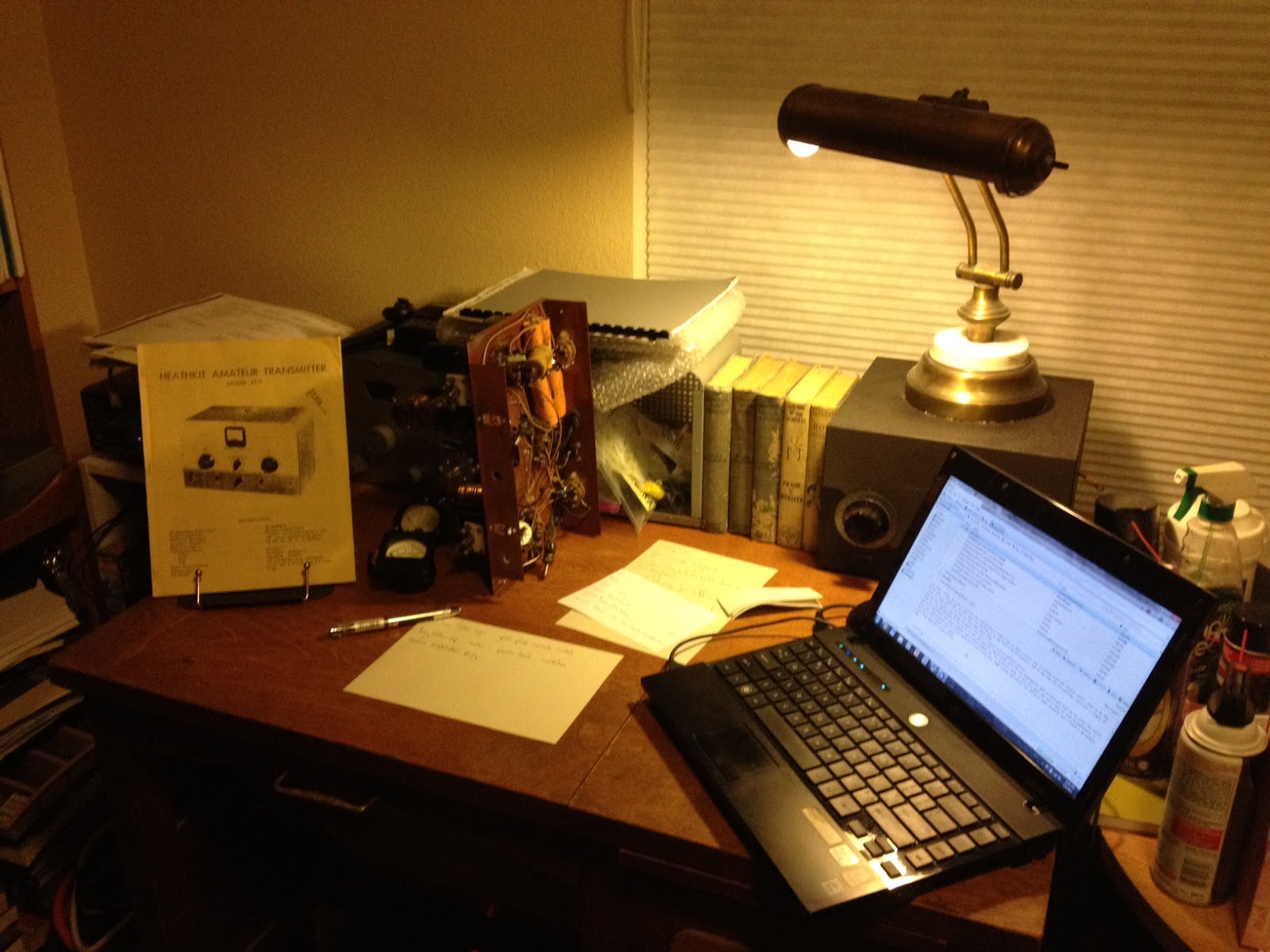 |
| The Heathkit AT-1 chassis with case and VFO-1 behind. |
There doesn’t seem to be any show stoppers although the wafer of the meter switch has broken in two and will need to be repaired. If I’m not able to repair it then thankfully it is fairly simple and replacement rotary switch can be substituted.
This isn’t going to be a museum quality restoration but the changes that were made to this transmitter in the past were sensible and if left in place are representative of period modifications. The original meter for example was not the highest quality and a Western or Simpson replacement would be an improvement. The original slide switches have been replaced with period snap-toggle switches which are also an improvement over the original.
The Heathkit VFO-1 however has been modified for grid-block keying which is a significant departure from the original and I plan to revert it back to cathode keying. Although a technical improvement it is not in keeping with the original design and needs to be undone. Everyone will have their own opinion but I think if I wanted modern circuits I’d get a more modern rig, so the VFO-1 will be returned to stock.
Hopefully I can carve out a bit of time here and there to work on this and slowly return it to working condition.
Owen Morgan, KF5CZO, is a regular contributor to AmateurRadio.com and writes from Texas, USA. Contact him at [email protected].
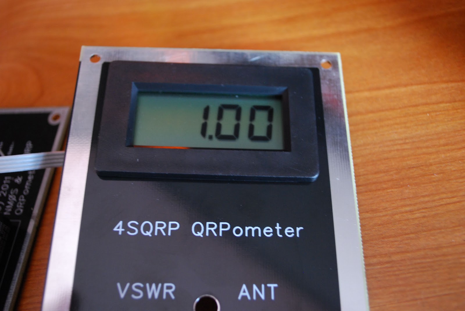
QRPometer ready for action
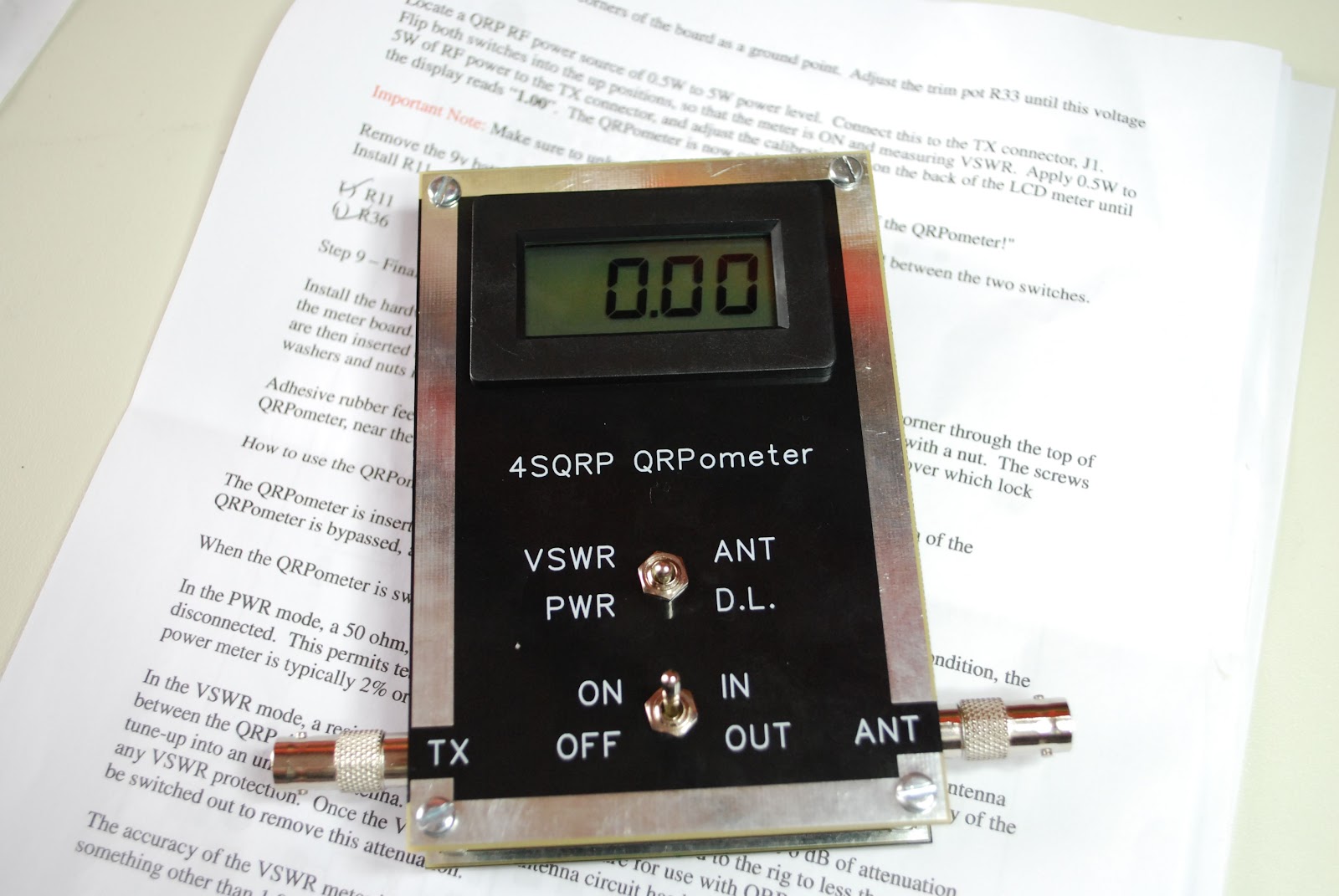 |
| QRPometer complete |
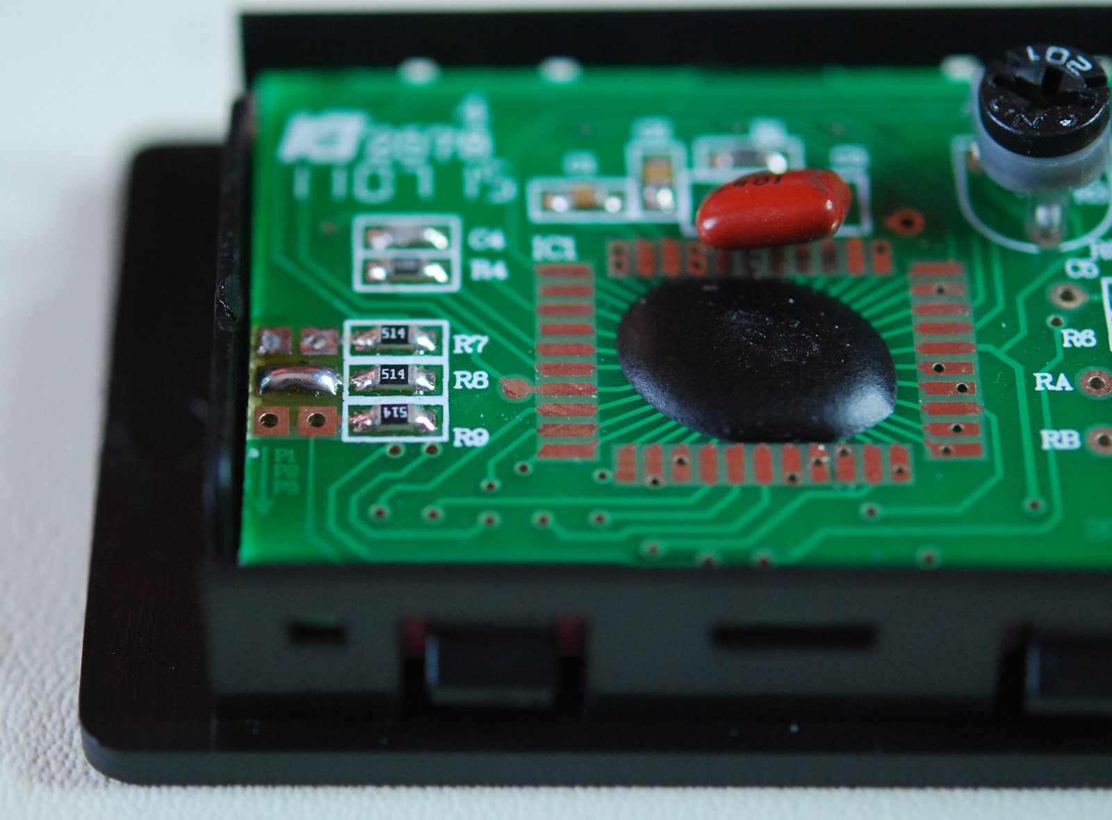 |
| Solder blob mod done |
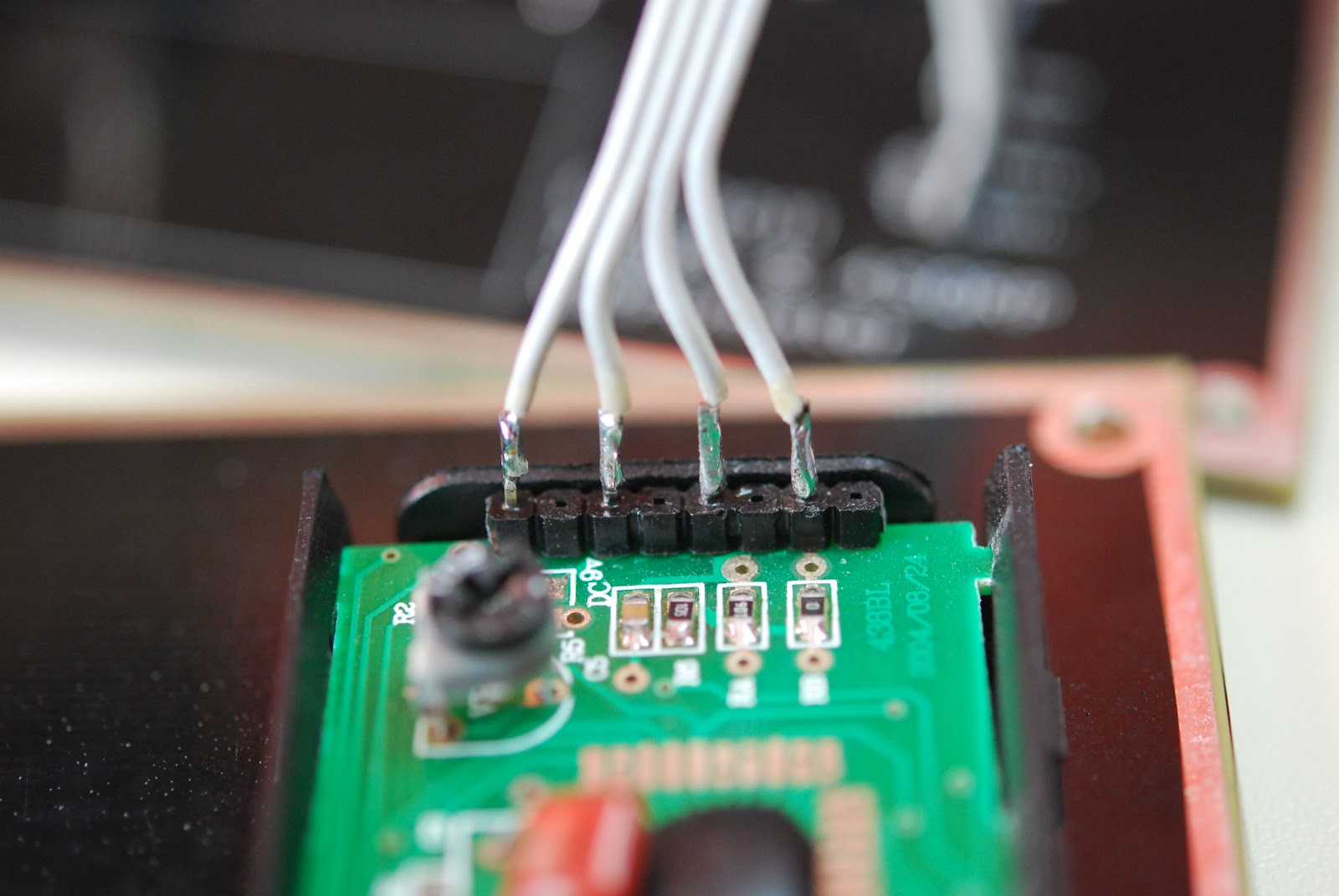 |
| Ribbon cable soldered to LCD |
The kit pro's
1. Very easy to build and calibrate
2. No toroid or SMD for those kit builders who shy away from them.
3. Instructions are well written and very easy to understand.
4. Meter has a built in dummy load when measuring power.
5. When meter is turned off it can still be left in series with antenna and transmitter the meter is in bypass.
6. Professional silk screen front panel.
7. Parts layout on the the circuit board are...may I say "Elecraft quality"!
Con's
 |
| Calibration complete |
2. There is no cover for the back of the circuit board.
So lets put 2 and 2 together.......7 pro's to 2 con's = home run!!
Mike Weir, VE9KK, is a regular contributor to AmateurRadio.com and writes from New Brunswick, Canada. Contact him at [email protected].
WØ/FR-194 (Genesee Mountain) 2520m / 8268ft
As mentioned in the activation alert from last week, I attended a local amateur radio club meeting on Saturday morning and presented Summits On The Air (SOTA) to the club membership. My presentation covers all aspects of both chasing as well as activating and I had available all my normal activation gear on hand. There were approx. 25 members on-hand for the presentation and I would estimate by the amount of questions, that at least half (perhaps more) will become active chasers.
After the meeting and a brief lunch, six of the members accompanied me on the activation of Genesee Mountain. Genesee Mountain is part of the Denver Parks and Recreational System. It is a well maintained area with a paved road providing an easy walk about 90% of the way.
The six other amateurs accompanying me wanted a nice leisurely first SOTA experience and that is exactly what I wanted to provide them. The original plan was to drive all the way to the top, park and then hike down 100 vertical feet, then back up. However, Genesee Mountain park road wasn’t open all the way the highest parking area. The main parking area is less than 1 mile (0.8 to be exact) from the summit with an elevation gain of about 200 feet. Everyone in the group felt comfortable with this hike and we took a nice easy stroll to the top. I handled packing the communications equipment needed for the activation.
We reached the summit just before 2100 UTC (3 PM local) and quickly began setting up the Buddipole Versatee Vertical for 20m. I briefly explained the setup and began calling CQ at 2115 UTC. Within just a few minutes I had the first QSO in the log and we took turns working each station until everyone had their four (or more) QSO’s in the book.
I (we) worked a total of 10 stations including N1EU, K7ASQ, K7ATN (S2S), WA2USA, ND9Q, KK1W, AD5A, WB9WHQ, K6ILM and W5DLD.

In the above photo, KDØBIK (red shirt) helping NØHIO work his first SOTA activation. I would like to thank NØHIO for providing the photo and video of the activation.
I’m fairly certain those who participated in the activation will all perform their own activations in the near future. I’m also hoping to get another SOTA activation planned in the next couple of weeks. The KX3 should arrive (hopefully) in the next 2-3 weeks and of course I will need to test it out and the best way I know of doing that is Summits On The Air.
Until next time…
73 de KD0BIK
Jerry Taylor, KD0BIK, is a regular contributor to AmateurRadio.com and writes from Colorado, USA. He is the host of the Practical Amateur Radio Podcast. Contact him at [email protected].
A Wasted Trip Thoroughly Unwasted
Last Saturday I picked up Andrew (KCØYFY) and his wife Joleen (KDØDOT) at 8:00 A.M. and headed for the monthly meeting of the West Central Minnesota Amateur Radio Club. It’s a 45 minute drive from Granite Falls, so we had plenty of time to talk. But once we got to the location of the meeting, our conversation took an abrupt turn. We were the only ones there!
Andrew asked, “You don’t think the meeting got canceled because of Easter weekend?”
I groaned. No way! “Here,” I said, grabbing my cellphone, “let me give Dean a call.” Dean (NYØI), the fellow who first invited me to join the club, is the Energizer bunny rabbit of ham radio — especially when it comes to building and maintaining the VHF/UHF repeaters out our way. But we quickly discovered that none of us had his phone number.
“Wait a minute!” I said. “We’re HAMS! Let’s call somebody on the radio!” What a novel idea. To think of using a radio instead of a cell phone to call another ham! I put down my cellphone and grabbed my HT. “NØIP monitoring,” I called on the local repeater.
“NYØI,” came back Dean! “The meeting has been rescheduled to next Saturday,” he explained when I inquired. “We published it on our Facebook page and announced it on the net. Sorry!” Again, I groaned. Down in Granite Falls I can’t hear the repeater they use for their net, and I long ago suspended my infernal Facebook account. “But how about I meet you for breakfast?” Dean asked.
I looked at Andrew and Joleen, who nodded. “Sure!” I replied. “Where do you want to meet?”
After getting directions to a small-town diner just up the street, we headed there and found a table. Within minutes, Dean arrived. When the waitress came by, he asked, “What’s your birthday special?”
“It’s your birthday?!” I asked. Sure enough, it was his birthday, and he had dropped everything to meet us at a moment’s notice. What a guy!
After a great conversation that ranged from ham radio to church life, Dean invited us up to the repeater site on the edge of town. We piled into our cars and headed over to the tower of the local FM broadcast station, where Dean pointed out three verticals mounted partway up. These were the antennas for the two repeaters he had there, he explained. Two huts crouched at the foot of the tower; one was the FM broadcast station’s, and the other the local sheriff’s (for their own repeater which used an antenna at the very top of the tower). Dean took us into this second hut, which also contained his two repeaters — one on 2 meters, and the other on 75 cm.
I had never seen a repeater in my life. Dean explained how they worked, and he told us about past equipment and current plans to improve what they had. Having been an HF CW guy all my life, I felt like a tourist in a foreign country — and I enjoyed every minute of it! After thanking Dean, the three of us headed back to Granite Falls.
On the long drive home, we continued the conversation we’d begun on the way there. The local ARES® Emergency Coordinator position is open, and Andrew is wondering if I might consider taking it. I promised him I’d contact the DEC and learn more about what is involved. Lots to think about!
As far as attending the club meeting that never happened, I suppose it was a wasted trip. But thanks to Andrew, Joleen, and Dean it most definitely was not wasted! After all these years as a ham, I’m finally meeting fellow hams in person. I wish I’d done it sooner.


![]()
Todd Mitchell, NØIP, is a regular contributor to AmateurRadio.com and writes from Minnesota, USA. He can be contacted at [email protected].
Lido Key 2012 Wrap-up, Part 3
You might want to read Part 1 and Part 2 of this series if you haven’t already done so.
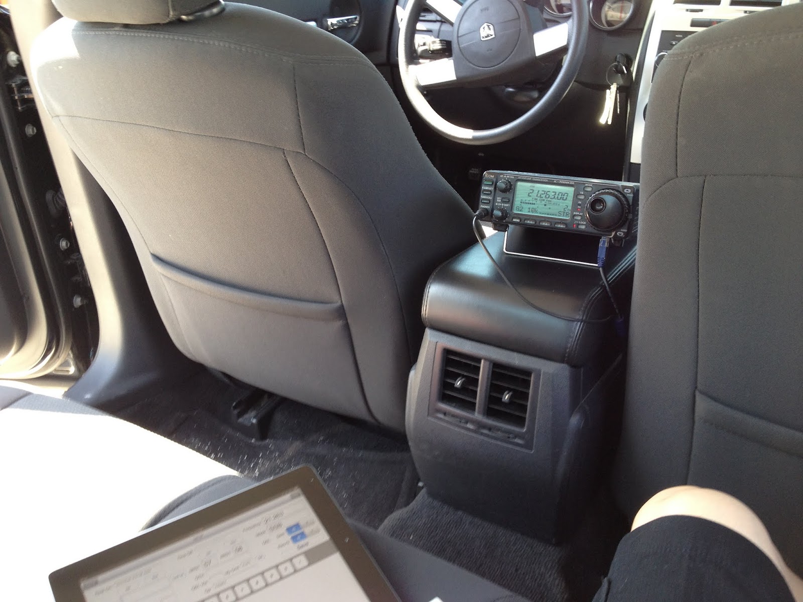 Originally, my wife Sharon and I were going to spend the full day “playing tourist” together on our last day of the trip, and I hadn’t planned on doing any additional radio operations. However, things changed and since Sharon had plans with her Mom, I decided to head back to South Lido Beach for one more day of operating. I got a much earlier start than the previous days, and set up in the same place that I did before, operating from inside the car. I was on the air at just around noon local time, but I got off to a very slow start, with only three contacts in that first half-hour. However, thanks to the magic of the packet cluster network, once I got spotted (initially by N8ZI, thanks!) things got a lot busier, and with more spots there were a lot more stations calling, who in turn spotted me again which brought another wave of stations calling. For that afternoon, ignoring the initial “slow start”, I wound working a station about every 2 minutes over the next 2 1/2 hours. Considering that in a few cases (one of which I’ll mention specifically) I stopped and chatted for several minutes, I was extremely pleased with that rate.
Unlike the previous days, the final day of operation went very smoothly, with no hitches at all. I operated entirely on 15m, and aside from some fairly deep QSB (fading) that was problematic from time to time, propagation seemed to be very good into central Europe as well as both the northeast and western United States.
One of the more memorable contacts I made was with Budd, W3FF. Budd is the “Budd” in Buddipole, and while we’ve emailed back and forth on several occasions, this was the first time we’d ever had a contact on the radio. When he first called me I had some trouble hearing him due to the previously mentioned QSB. He’d tried to work me on the previous day while “pedestrian portable” (that’s walking around with an HF radio and antenna), but I wasn’t able to hear him. For this contact, he was working from his home station, and he had to turn on his amplifier so that I could hear him more clearly. It was fun getting to speak to Budd, and after a while we finished and I went on to work more stations.
After returning home, a little quick analysis of my log showed the I made 119 contacts with 116 different stations (I worked 3 stations twice each) located in 24 different countries. As of the time that I’m writing this, I had 33 of those contacts confirmed via Logbook of The World and another dozen who send me QSL cards directly through the mail, including 3 DX stations. (I won’t see any bureau cards for at least another 6 to 12 months). With the help of my son Brett who did the design work, I was able to print out the cards needed to confirm those contacts, making sure to include both the IOTA number and island name as part of the card. (This is a requirement of the IOTA programme and and I wanted to ensure that the folks who got a card for me were able to use it for confirmation of their contact with NA-034.)
All in all, I had a great time operating, and I look forward to doing it again.
Here’s the list of countries that I contacted:
| Prefix | Country name |
| CT | Portugal |
| DL | Federal Republic of Germany |
| EA | Spain |
| EA6 | Balearic Islands |
| EA8 | Canary Islands |
| ER | Moldova |
| F | France |
| FG | Guadeloupe |
| G | England |
| HA | Hungary |
| HB | Switzerland |
| HC | Ecuador |
| HI | Dominican Republic |
| HR | Honduras |
| I | Italy |
| K | United States of America |
| KP4 | Puerto Rico |
| OE | Austria |
| OK | Czech Republic |
| SM | Sweden |
| SV | Greece |
| UA | European Russia |
| VE | Canada |
| YU | Serbia (ex-Yugoslavia) |
 Ham Radio Deluxe |
 W5SWL Electronics |
 Ham Radio Prep |
 KB3IFH QSL Cards  Hip Ham Shirts  HamRadioAuctions HamRadioAuctions Reliance Antennas Reliance Antennas Enigma Shop Enigma Shop |  morseDX  Ni4L Antennas  R&L Electronics R&L Electronics antennas.us antennas.us QRV QRV |
- Matt W1MST, Managing Editor
