 |
 Georgia QSO Party this weekend
Got this nice e-mail from John K4BAI, QRPer and contester, exemplar :
Hi Larry:
Hope you will be able to participate in our annual Georgia QSO Party on Apri1 14 and 15. All information can be found on the GQP Home Page at http://georgiaqsoparty.org. It runs 10 hours on Sat (1800Z to 0359Z Sunday) and 10 hours on Sunday (14Z to 2359Z) on 160 to 6 meters CW/Digital and SSB. Georgia with 159 counties has more counties than any other US state other than TX and the small size of most of them means that the mobiles and rovers are frequently changing counties.
Suggested frequencies are 1815 and 45 kHz up on CW and on 1865, 3810, 7190, 14250, 21300, and 28450 SSB. Also 50095 and 50135 on 6M. Digital would be near traditional digital calling frequencies. Multipliers for Mixed Mode stations are counted per mode (not per band).
Band conditions have been pretty good recently, including 20M often being open at night and 15 and 10 providing a lot of QSOs during the daylight hours.
Rapidly moving mobiles have been a hallmark of the GQP, particularly on CW.
Please join in the fun for as much time and you can and send in your log.
Awards are available for high power, low power, and QRP entries from the various states, provinces, countries and GA counties.
Thanks for your support and for passing this information on to others who might be interested.
I should be QRV from many GA counties as W4AN/M.
73, John, K4BAI.
So folks, if you have some time this weekend, let’s support our fellow Hams from the great state of Georgia. There should be lots of activity – build up your logs and perhaps even be the QRP winner from your state!
72 de Larry W2LJ
QRP – When you care to send the very least!
Larry Makoski, W2LJ, is a regular contributor to AmateurRadio.com and writes from New Jersey, USA. Contact him at [email protected].
Handiham World for 11 April 2012


- The cable is good and ready for use.
- The cable is open through the outer shield.
- The cable is open through the center conductor.
- The center conductor is shorted to the shield.
- An intermittent condition exists that causes a short or open when the cable is flexed.
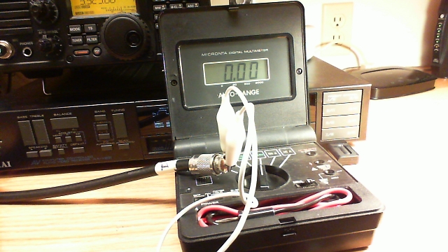
Photo: Simple test gear for a continuity check includes a clip lead and a multimeter with a continuity buzzer.
- Take one end of the disconnected coax. Remember, we are NOT able to test continuity with the coax connected to any equipment or antennas. Touch one multimeter lead to the center pin of the PL-259 plug and the other to the outer metal part of the plug. You should hear nothing, indicating that the cable is not shorted. This is always the first test, because we must eliminate the possibility of shorts before we can make any assumptions about the center conductors or the shield.
- Next, take the clip lead and use it to short the coax at one end by connecting the center pin of one of the PL-259 connectors (it doesn’t matter which one) to the shield side of that same connector. Take the free end of the coax and touch one multimeter probe to the center pin and the other to the metal shield of that PL-259. You should now hear the buzzer that indicates continuity.
- You have now completed the basic tests, because you have determined that the cable is not shorted and by passing a current through the entire length of the center conductor and back through the shield, you have determined that both the center conductor and shield are intact. The final test is to flex the cable and wiggle the connectors while performing both of these tests again. If it helps, you can add two additional clip leads to connect the multimeter probes so that you don’t have to try to hold them in contact with the PL connectors. This will help determine if the cable is intermittent.
- If the cable fails any of the tests, feel free to test the shield to shield and center pin to center pin connections separately. Never use a cable that is suspect, because it could cause damage to your equipment.
- Last but not to be missed is a final check along the length of the cable for any obvious bad spots, such as a break in the outer jacket or any suspicious bends or bumps in the cable.
Patrick Tice
Handiham Manager
Pat Tice, WA0TDA, is the manager of HANDI-HAM and a regular contributor to AmateurRadio.com. Contact him at [email protected].
Speaker failure

Yesterday the Medion computer speakers that I used with my Elecraft K3, failed. I was WSPRing on 10m and had the speakers switched off at the time but I saw some unusual interference on the waterfall and switched them on to listen. Nothing happened. No audio, nor did the blue power LED light up.
I checked the obvious things such as the cables and that the power supply was delivering 14V DC. It was. I took the speaker containing the audio amp over to the workbench and tried it on the bench power supply. Although the speaker was behaving as if no power was being applied, 20mA was being consumed when the switch was on. I have no idea where it was going.
Without a schematic there isn’t much I can do but I doubt that the speakers are repairable anyway. There are no active components on the circuit board apart from one integrated module attached to a small aluminium heatsink. This has presumably let its smoke out. There are a number of capacitors on the board and the cable connections are extremely well filtered against RFI. I have never seen such attention paid to preventing RFI. I guess that this is because Medion is a German company and Germany seems to be the only country that takes compliance with EMC standards seriously. The speakers were almost completely immune even when I ran 100W. Having a tone control they produced very rich-sounding audio from the K3, unlike its internal speaker which is shrill to listen to and has very little bass response.
I’ve now replaced the Medions with a pair of passive speakers that I originally got for this task but with those the audio sounds boxy no matter how I fiddle with the K3’s RX EQ settings. The only benefit of them is that I’m using one less wall wart!
These Genius speakers look like they might be a good replacement but ordering a pair would be a lottery as I have no way of knowing if they are RF-proof enough. One pair of Logitech speakers I bought were a dead loss. They were handed to the local Oxfam shop within an hour of the postman delivering them as they were so sensitive to RF they were beyond hope.
Julian Moss, G4ILO, is a regular contributor to AmateurRadio.com and writes from Cumbria, England. Contact him at [email protected].
Update to the FM VHF Operating Guide
I did a little updating on my FM VHF Operating Guide. Take a look.
Your feedback is appreciated.
73, Bob K0NR
Bob Witte, KØNR, is a regular contributor to AmateurRadio.com and writes from Colorado, USA. Contact him at [email protected].
The Menta

MakerShed announced a new product that will probably appeal to radio artisans who like to build little rigs. It’s the Menta, a smaller version of the Arduino which fits nicely in the venerable Altoids tin.
Get a few 2N2222s, some toroids, resistors, and a crystal soldered on the prototyping area, then burn some CW keyer software on the Arduino and voila, you got a nice little QRP rig.


The further adventures of the Heathkit AT-1
Work has been conspiring to eliminate my spare time but I was able to spend a few hours over the Easter holiday to clean up the shack and make space to put the Heathkit AT-1 on the desk again. I have been able to spend a little time going over parts that need to be replaced and making a list.
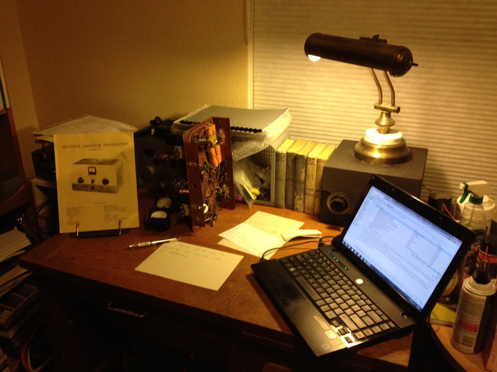 |
| The Heathkit AT-1 chassis with case and VFO-1 behind. |
There doesn’t seem to be any show stoppers although the wafer of the meter switch has broken in two and will need to be repaired. If I’m not able to repair it then thankfully it is fairly simple and replacement rotary switch can be substituted.
This isn’t going to be a museum quality restoration but the changes that were made to this transmitter in the past were sensible and if left in place are representative of period modifications. The original meter for example was not the highest quality and a Western or Simpson replacement would be an improvement. The original slide switches have been replaced with period snap-toggle switches which are also an improvement over the original.
The Heathkit VFO-1 however has been modified for grid-block keying which is a significant departure from the original and I plan to revert it back to cathode keying. Although a technical improvement it is not in keeping with the original design and needs to be undone. Everyone will have their own opinion but I think if I wanted modern circuits I’d get a more modern rig, so the VFO-1 will be returned to stock.
Hopefully I can carve out a bit of time here and there to work on this and slowly return it to working condition.
Owen Morgan, KF5CZO, is a regular contributor to AmateurRadio.com and writes from Texas, USA. Contact him at [email protected].
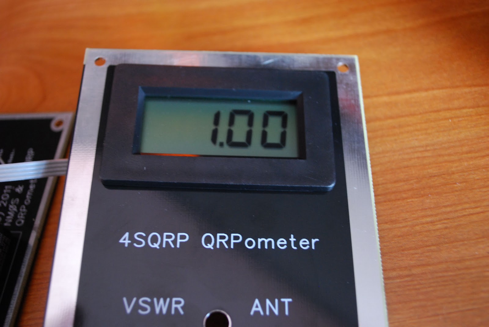
QRPometer ready for action
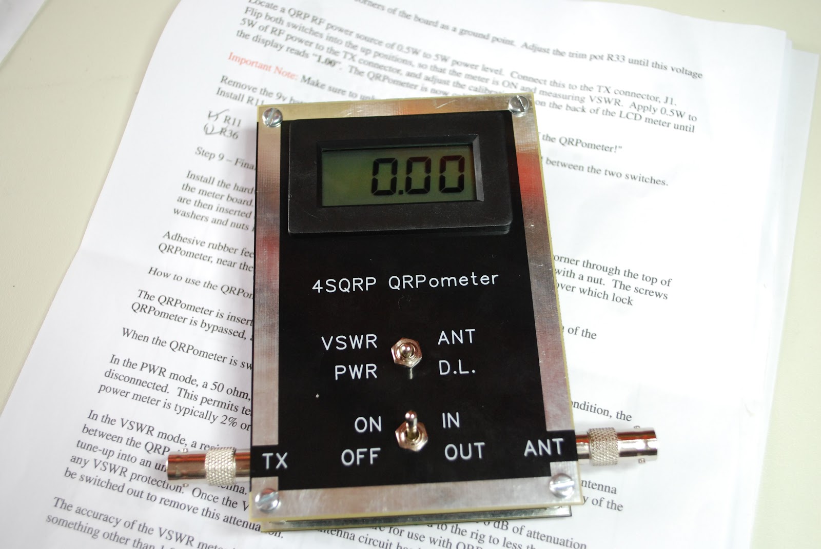 |
| QRPometer complete |
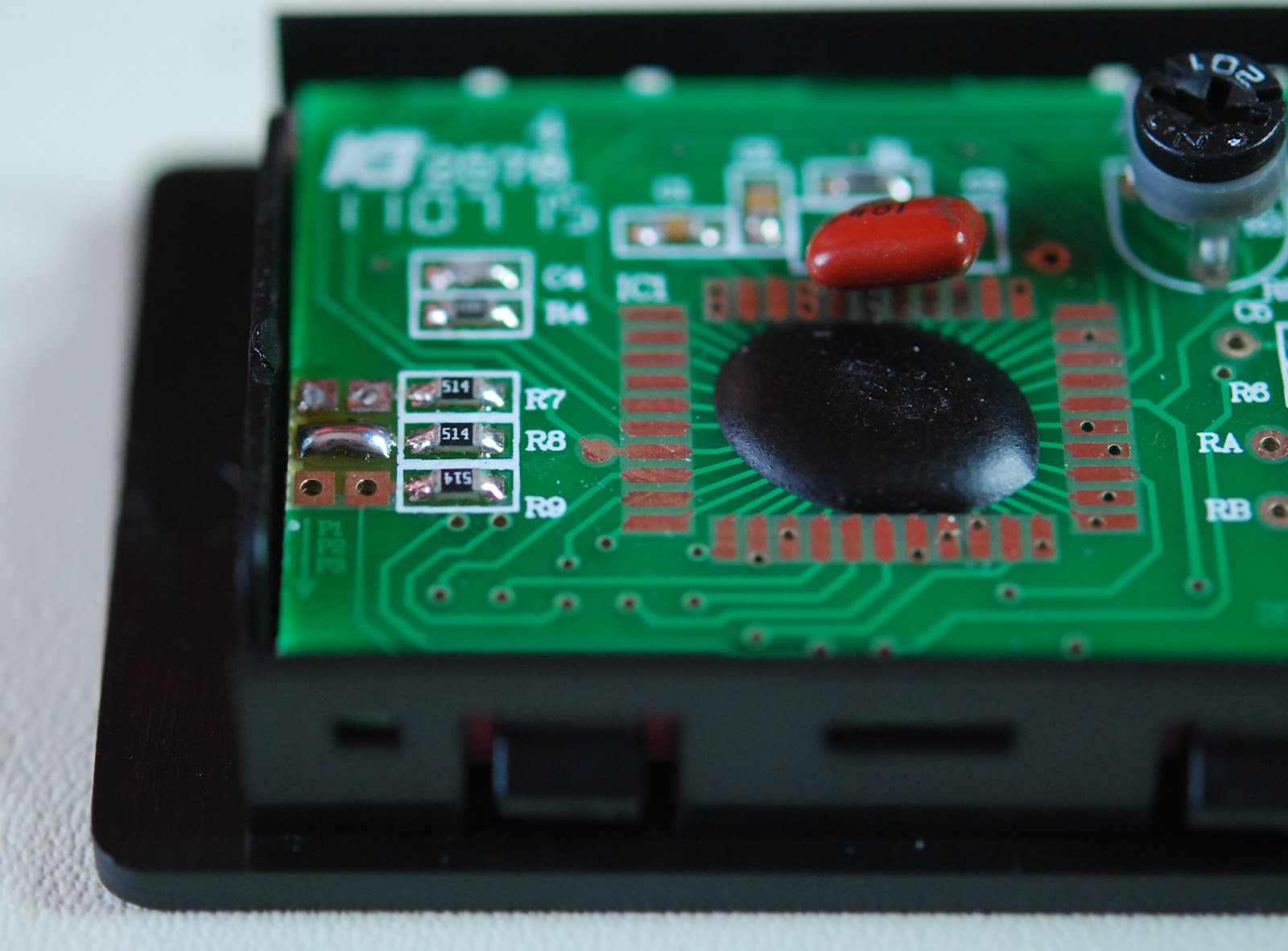 |
| Solder blob mod done |
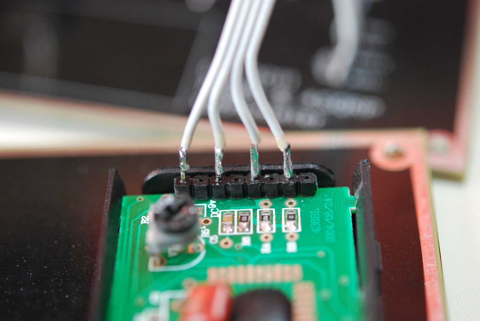 |
| Ribbon cable soldered to LCD |
The kit pro's
1. Very easy to build and calibrate
2. No toroid or SMD for those kit builders who shy away from them.
3. Instructions are well written and very easy to understand.
4. Meter has a built in dummy load when measuring power.
5. When meter is turned off it can still be left in series with antenna and transmitter the meter is in bypass.
6. Professional silk screen front panel.
7. Parts layout on the the circuit board are...may I say "Elecraft quality"!
Con's
 |
| Calibration complete |
2. There is no cover for the back of the circuit board.
So lets put 2 and 2 together.......7 pro's to 2 con's = home run!!
Mike Weir, VE9KK, is a regular contributor to AmateurRadio.com and writes from New Brunswick, Canada. Contact him at [email protected].
 Ham Radio Deluxe |
 W5SWL Electronics |
 Ham Radio Prep |
 KB3IFH QSL Cards  Hip Ham Shirts  HamRadioAuctions HamRadioAuctions Reliance Antennas Reliance Antennas Enigma Shop Enigma Shop |  morseDX  Ni4L Antennas  R&L Electronics R&L Electronics antennas.us antennas.us QRV QRV |
- Matt W1MST, Managing Editor
