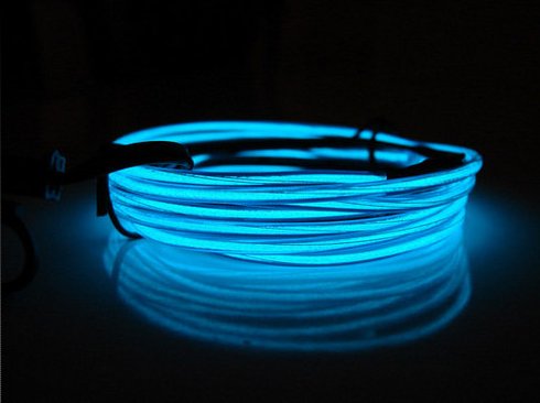
 Inverted High Frequency Loss with LMR-450G
By John ‘Miklor’ K3NXU
PERFORMANCE TESTS – LMR-450G
The recently announced LMR-450G cable has aroused much curiosity since its characteristics have not been collectively available by any one source. By multiple inquiries to several manufactures (only three at this time) and numerous lab tests, we hope to put many of the existing questions to rest.
DESCRIPTION
The physical make up of this cable varies slightly from most conventional RF cables. The center conductor is a semi-stranded copper alloy surrounded by Telfon, which will absorb and distribute cable ‘hot spots’ caused by excessive standing wave. The double silver braid and foil outer coating which provides a 98.6% shield is what the inverted high frequency loss characteristics are attributed. The loss is substantially less as the frequency increases, making this cable especially attractive for UHF, cellular, PCS and microwave applications.
LOSS PER 100′
30 MHz 2.4 db
50 MHz 2.1 db
150 MHz 1.6 db
450 MHz 1.1 db
800 MHz .51 db
1200 MHz .37 db
1950 MHz .31 db
The cable’s most unique property is attributed to the outer jacket material Neo-glow, an RF sensitive composite plastic which will visibly indicate RF ‘hot spots’ in the cable. Adjusting the cable length to the antenna system for the ‘perfect’ impedance match is crucial at high frequency, thus the importance of a low SWR for peak performance.
PROPER INSTALLATION
The low level emission of light from LMR-450G cable can be enhanced by wearing lightly tinted sunglasses with UV protection, which enhances the light radiation from the cable. Select an approximate length of cable needed for the installation which must be multiples of a 1/4 wavelength for the desired frequency. The exact length can be determined by using the formula 467 / Freq (MHz) plus approximately 18 inches.
The initial tests should be run with a 50 ohm dummy load at one end of the cable. With a minimum of 7 watts from the transmitter, you will see a faint glow from the cable indicating the ‘hot spots’ to be eliminated. These are the points along the cable where the RF is at its maximum. It is at these points where the RF connectors should be mounted. Trimming the excess cable may be required at both ends of the cable to produce the most effective match. Use caution not to trim too much cable as the loss characteristics improve with longer cable lengths.
SUMMARY
This could be the beginning of the long awaited high frequency “SUPER” cables. Only available in limited quantities at this time; contact your local cable supplier for more details.


Good one! It brought a smile to my face!
what’s the date today ? i think it’s april 1st, good one! 73 88
sorry forgot callsign de g4wqz ttfn