Archive for the ‘radio’ Category
 One-step dipole pruning
 January 2nd, 2011 |
  Author:
 Dad and I built a 10-meter rotable dipole some 12-13 years ago using pieces of a large Wilson tribander that I had begged off of a local ham. It was an interesting mechanical design, using a 3/4-inch CPVC tee fitting as the center insulator and mounting bracket. The third leg of the tee slipped over a piece of EMT conduit that we had crimped. The EMT, in turn telescoped into a RadioShack-type TV mast, which was bracketed to our deck. It was a fun antenna back when 10 meters was fun.
That CPVC tee lasted a good deal longer in the UV and wind than we ever imagined. Granted, the antenna was stored in my folks’ garage for 7-8 years while I was in college and graduate school. But, I reinstalled it when we moved to Maryland. Last week brought high winds to the Mid-Atlantic region and the fitting gave up the ghost:
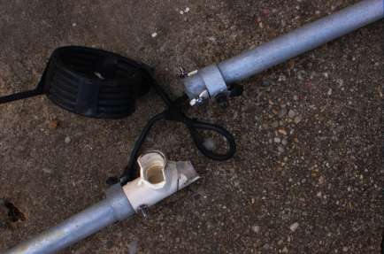
Fortunately, it takes all of a half-hour and another 33-cent fitting to replace it. I did think of running a piece of pipe, dowel, or fiberglass across the element for extra strength. But, I’ll do that if it fails again soon. The process of repairing the antenna reminded me of the technique we used to tune it, which we thought was very clever at the time.
We used the “magic” 468 to set the initial length of the antenna optimized for 28.400 MHz, which was totally wrong since 468 is intended for bare wire, not tapered aluminum. Then, we installed it and measured the VSWR across the band (in the shack). Next, we took the frequency of the minimum VSWR and divided that by the design frequency. Then, took the antenna down and scaled the length of the antenna by the quotient from the previous step. Finally, we reinstalled the antenna and measured the VSWR across the band. It hit dead-on. Dad was impressed that my first two QSOs were KL7 and ZS! It was, of course, ten meters when ten meters was good.
This may be old-hat to a lot of folks, but we thought we were geniuses at the time, although it was purely an act of shade-tree engineering! For those who don’t mind watching sausage made, I will now muse on the validity of the technique.
Suppose you have a “magic factor,” M (=468 or whatever), that defines the frequency of minimum VSWR for an antenna of length l:
 Rearranging that will be useful later:

If we take the partial derivative of each side in the first equation, and substitute M from the second equation we get the following relationship:

Cross-multiplying/-dividing and abusing the partial derivative notation to be a small perturbation yields:
 This is subtly different from the original technique, which can be derived from this using some small-number approximations. But, the point is that there exists a simple technique to prune a dipole to resonance. delta-f is the offset between the design and actual VSWR minimum frequencies, f is the design VSWR minimum, l is the design length, delta-l is the amount that needs to be added (pruned).
LoTW tools
I have assembled some of my tools for massaging logs for upload to the ARRL’s Logbook of the World (LoTW). They’re written in perl and should run with just about any modern perl distribution, including that found on Macs and GNU/Linux distributions.
The principal features are: conversion from TRLog log.dat and mangled Cabrillo files to ADIF and fixing hour offsets.
Ruling the Air
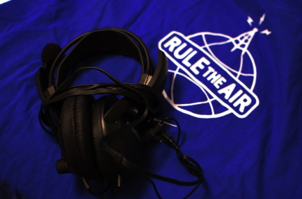
I rolled over another year on the odometer of life last week and as is the custom around here, I received some gifts, several of which were radio-related. The shirt is from my wife. The Yamaha CM500 headset is from my parents.
Both of these came in good time since my “CW is the Real Thing” shirt is getting threadbare and my ProSet developed a bad spot in the cable in the past week. I got to try them both out for a brief period at the W8AV multi-two operation in the CQ WW contest over the weekend.
The CM500 (the manufacturer page for these is gone, but you can get them from the usual places) came as highly recommended by the denizens of the Elecraft reflector via the PVRC reflector. They’re pretty good headphones. The sound is good and they have plenty of volume when driven by a TS-930. The ear pads are a little thicker than those on the ProSet, which is good because after a few hours, my ears feel pinched by it. The big downfall of the CM500 is that it feels a little bit like my head is in a vise when I wear them. There may be an adjustment for that.
I was originally thinking that I should send the ProSet back to Heil to be refurbished. But, the price is much higher than I remembered. Fortunately, they stock parts for the old models. So, I will be doing the refurbishing myself.
In WW news, I only operated for about two hours on Sunday afternoon at W8AV. Goose replaced his big tower with a new one and the lower 40-meter antenna was not back up yet. But, with a single 2-element Yagi at 140ish-feet and 1.5 kW from a homebrew 8877, I easily carved out a spot around 7064 kHz at 2000 UT and ran off a nice string of Europeans just as the band was opening.
W1GHZ 1296 MHz RX working!
I spent about two hours last night assembling the W1GHZ 1296RSU and 1152LO boards from his paper “Multiband Microwave Transverters for the Rover—Simple and Cheap.” Once again, I trekked over to W3APL beacon site at lunch and put the pair through their paces on RX with the IC-290H as the IF radio. It worked! Here’s a clip:
One of the interesting things about the 1296-MHz beacon is that it’s FSK, not CW. You’ll notice this after about 15 seconds when it starts sending its callsign. The higher pitch tone is “keyed” and the lower is “unkeyed.” Brian, ND3F, was at the beacon site with us last week to check out a problem (turned out to be a dead power supply fan). He told us that it’s common for microwave beacons to operate in FSK mode so you always have a carrier to tune across (and swing your antenna across). Who knew?!
Anyhow, it’s time to start building the other trappings, including enclosures, sequencers, filters, PAs, and T/R switches! Apart from the PA parts and some connectors, the other components are on-hand and ready.
Raytracing
Today we have a little bit of fun ham-related tinkering from work. This is two different frequencies transmitted from the same site.
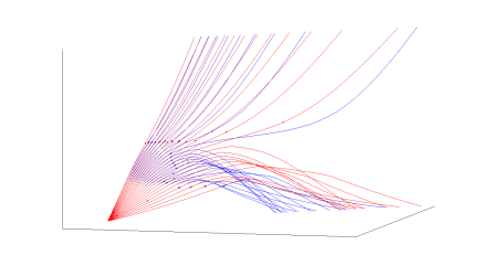
There are lots of neat details in a ray-trace: skip focusing, Pedersen rays, mode-splitting, … One thing that’s fun about writing your own models is that you can modify (intentionally or not) the model physics to do unphysical things…
The second run shows X and O modes for a single frequency and a failed attempt at modeling an MF signal into an E-F region duct. (The ducting, by the way, has nothing to do with my actual work. I was simulating it for ham purposes, although it helped me uncover a problem.) The signals do get to the duct, but they bend the wrong way. This has been fixed in the code, but it serves to remind that modelers have complete control. The background ionosphere is relatively unphysical in this one as well…
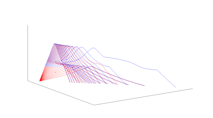
The raytrace code used above is small, simple, and written in MATLAB. I doubt that it will ever be released publicly, but if so I will note it here on the blog.
A Follow-up to “New QSL card”
This is a follow-up to a post from Sunday.
On Wednesday night, Sarah handed me an envelope from the day’s mail that had the appearance of a QSL card. I took out my knife and opened it. It had a some sample QSL cards, along with a brochure inside. I scratched my head for a moment and concluded that I had just received my first QSL card for a blog post.
This curious turn of events brings me around to a couple of points. For those of you who don’t know, this blog is aggregated by AmateurRadio.com (and it is syndicated on my Facebook profile). My agreement with the owner of AmateurRadio.com is that he provides me with visibility in return for select content from my blog. The QSL printer who sent me the samples is one of his advertisers. Thanks, by the way! The cards were very beautiful and of high quality and I will consider him to print photo cards for my next DX operation. In full-disclosure, I received nothing from the printer who printed my cards in return for mentioning them. But, I should clarify that the blog is something I do for fun and I’m not really in the business of product endorsements.
A final point of clarification is that my beef with the available QSL cards was not so much the quality available, but amount of semi-relevant stuff hams try to cram onto the card. I guess if 10 meters ever opened up again regularly, we might start getting asked for our “Ten-Ten” numbers again. After listening to the V31BB clip about the secret decoder ring, I’m sort of ashamed to admit that I have one. Strike that from the card! The long and the short of the original post was that I wanted an uncluttered, distinctive card. And, I think I found it.
W1GHZ 903 MHz RX working!
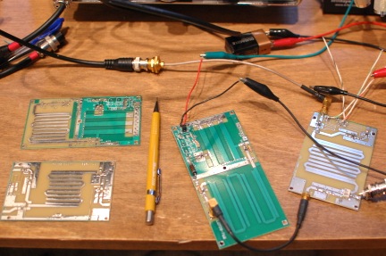
Although I built the W1GHZ 903-MHz transverter and 756-MHz LO boards last winter, I didn’t have time or inclination to test them until this week. These were purchased as a part of the first (October 2009) group buy orchestrated by W8ISS. Instead of the INA-10386 MMIC recommended by W1GHZ, the W8ISS kits featured a Sirenza SGA-3586Z MMIC as the LNA, as suggested by the 4s_microwave group. A better part (with NF < 2 dB), recommended to me by W9SZ, is the the SGA-4586Z, which I used on my 903 board and will use on my 1296 board. This requires the bias resistor (R3, 51 ohms, on the 1296 board) to be changed to 100 ohms.
Since there is a lot of foliage between me and the W3APL beacon, I took the liberty of carting the transverter and IF rig to the beacon site (sorry no photos) on my lunch break yesterday. Sure enough, it worked like a charm with the beacon pounding in on 147.0615 MHz. The nominal beacon frequency is 903.055 MHz, so I don’t know if the difference is in my LO or the not-GPS-locked beacon drifting around. At any rate, I’m pleased enough to continue the project…
The 1296RSU transverter and 1152-MHz LO boards are on the left in the photo above. They have not yet been populated, but that’s an evening’s work.