Archive for the ‘radio’ Category
 6m season
Guess what? Its sunny and there’s Es to be had about. After several months of not really touching the radio at home because of the various commitments I made to a certain cycle sportive I took a week off work and decided to catch up on the family and my hobby. After a nice long weekend away with the kids in Centre Parcs (If you don’t have kids then it’ll be hell on earth, otherwise I can recommend it, especially the security at Sherwood after our friends bike was pinched. The Muppet got nicked at the gate and is now at her majesty’s pleasure)

Back to radio though…A few quick fire contacts on 6m soon had me back in the swing although an attempt at FSK was a step too far today. Still nice to work a few stations and to see the sun out. The Powabeam is doing the business on a Moonraker mast. Not an ideal set up but useful.
Dayton 2013 Recap
Some good planning on Sarah’s part yielded a bridal shower for her sister scheduled on the same weekend as the Hamvention. Huge win.
- Speaking of huge wins, there was no sewer back up this year.
- Like the last time I attended in 2011, I’m pleased to see more younger (than me) hams in attendance. A high-ranking ARRL official noted to me the “energy and enthusiasm” present in this generation of young hams that was not present 15 years ago (this year marks my 20th year as a ham, but I didn’t mention that). Attendance was still thin compared to my first visit in the mid 1990s.
- Deals. I stimulated the economy by purchasing a small CDE rotor for my VHF activities, an HP server power supply for a future solid state amplifier project (>55 amps at 50 volts), a couple of 900-MHz antennas, and some miscellaneous small parts. I sold some junk to partially cover that expense.
- People. Ran into a lot of old friends and made some new ones. This is really why I go to Dayton, well, that and the junk. K8MFO tells me there are Bureau cards coming. W8AV has 930s for me to work on. W2NAF had people for me to meet. AD8P was able to win himself a pizza from an unnamed W5 in the “SB-200 challenge” of correctly differentiating an SB-200 from an SB-220 at a distance of 20 feet—a tribute to the W5′s failure to distinguish the two until after the sale last year.
- W2NAF has written an article about our trip to Adak (NA-039) that was published in the June 2013 issue of CQ. It has a lot more background detail than what I wrote on the blog. Check it out. I picked up a copy of that and the May 2013 issue which has the 2012 CQ WW CW results in it.
- Products. I just don’t care that much about new products. The Ten-Tec Rebel that several people have already discussed is a cool idea. I know that Ten-Tec took some flak for not opening up the Orion SDR core when they produced it. But, let’s be realistic, people. Hams would have bricked those suckers in a heartbeat. A sandbox “open source” radio is a step in the right direction, but I question what a ham can really customize that matters without screwing it up. Maybe I’m just not visionary enough. Almost 10 years ago now, I interned in the R&D lab at a large consumer appliance manufacturer as an undergraduate my supervisor was always saying, “How can we make this attractive to the [hardware] hackers?”
- Guns. The Hamvention web site was very specific that the Trotwood Police Department would be actively enforcing Hara Arena as a non-gun zone. Seriously? It’s a ham radio convention. Bill Goodman is there at least once a month the rest of the year. Do hams bring their go-kits to gun shows? They must. Inquiring minds want to know…
- Suites. I did not do the contester suite thing. Was thinking of going on Friday night but fell asleep in my in-laws’ living room. This is a recurring problem when I visit so no one bothered to awaken me.
Was the trip worthwhile? I think so.
A man walks into a bar…
A ham with a parrot on his shoulder walk into a bar.
Barkeeper asks “where did you get that?”
“Dayton” says the parrot.
David Cripe’s NM0S Cyclone 40 Meter Transceiver kit
Readers, check out the Cyclone 40 in this release:
A new kit from the Four State QRP Group and David Cripe (NM0S)

NM0S’s Cylcone 40M QRP transceiver. Look for it at Four Days in May!
Arising from Dave’s entry in QRP ARCI’s 72 Part Challenge Design Contest in 2010, the Cyclone 40 is an enhanced version of the original design. The transceiver designed for the design contest had 72 total parts, performed well, and won honorable mention. This improved version has less than 100 components and even better performance! The kit features all through hole parts and easy assembly. The receiver is a superhet design with very good sensitivity and selectivity, and tunes the entire 125 kHZ CW segment of the 40M Band – and does so at a comfortable tuning rate. A frequency readout is included so you know where you are at all times.
This is a complete kit, including the enclosure. A high quality board package includes the pc board, front and back panels, the sides, and top and bottom all of which make up the enclosure. The control and jack labels are silk screened in white letters and vividly contrast with the black solder mask, and the holes for the connectors and controls are pre-drilled. The ends are “dovetailed” together making a very rugged, easy to build, and attractive enclosure.
Features and Specifications
General
- Enclosure: A very nice predrilled and silkscreened enclosure is included. It’s easy to assemble and looks great.
- Ergonomics: Smooth solid tuning, a quiet receiver with QSK and well behaved AGC. Nicely laid out front and rear panels.
- VFO: The VFO is a simple PTO design, is very stable, and also quite easy to build
- Sidetone: Included!
- AGC: Audio derived, fast and smooth.
- Frequency Range: 7.000 – 7.125 typical.
- Tuning Speed: 10kHz/knob turn typical.
- Stability: 300 HZ the first 5 min after power up, less than 10 HZ/hour after that.
- QSK: Fantastic QSK! Full Break in, excellent muting, really fast!
- All Through Hole Parts There are NO SMT parts in this kit, and only three easy to wind toroids.
- Dimensions: 4.4 x 3.6 x 1.9″
- Power Connector: 2.5×5.5mm coaxial, center positive. Should be fused at 1A, fast blow at PS
- Antenna connector: BNC
Receiver
- Configuration: Superheterodyne, 11 MHZ IF, 4 Crystal IF Filter.
- Sensitivity: MDS (Minimum Discernable Signal) -125, Typical, below the normal 40M band noise level.
- Selectivity: Four crystal, 500 HZ IF filter
- IMD3: 90 dB typical, better than most commercial gear!
- IP3: +10 dBm typical – another very good number
- Frequency Readout: 3 or 4 digit CW, 1 kHz or 100 Hz resolution (user selectable), developed by Adrian Hill, KCØYOI.
- Band Edge Marker: A band edge marker is heard at 7.001 MHZ
- Headphone Jack: 1/8″ stereo, standard earbud/Walkman® headphone compatible
- DC Current consumption: 30 ma typical at 13.6 VDC.
Transmitter
- Configuration: Stable, Wide Range VFO (PTO design), Efficient Class E Final.
- Spectral Purity: All harmonics and spurs less than 50dB below the carrier.
- Output Power: approximately 4W into 50 ohms
- DC Current consumption: 500ma typical at 13.6 VDC Will operate down to 9v DC.
- Key Jack: 1/8″ stereo, grounded shell, switching the tip keys TX. Contacts accessible for an internal add-on keyer
Kits should be available at QRP ARCI’s Four Days in May conference at Dayton, and will be for sale on the Four State QRP Group’s web site approximately May 20th. The final price hasn’t been determined yet but should be less than $100 plus shipping.
W3APL/B 903-MHz beacon
Late last Summer, it came to my attention that the 903-MHz W3APL beacon had gone off-line. The failure was intermittent and seemed to resolve itself after power was reset. Several efforts to troubleshoot it were undertaken by myself and others, including running it at high duty into a dummy load over a period of days. I was unable to get the problem to manifest itself on my bench.
A synthesized source (Analog Devices demo board) was offered by a friend of the Club, however it did not produce the desired output (or any output at all). It’s not clear whether this was the fault of the synthesizer or the user (me). The notional plan was to replace the beacon, which consists of a 75-MHz crystal oscillator followed by 12x of multiplication and a small RF power module, with the synthesizer and a new RF power module. The project languished, as they often do in my hands. But, two weeks ago I picked up the task again and made some real headway.
Really, the failure had to be one of a couple of things: 1. Intermittent connection exacerbated by thermal cycling. 2. Oscillator “unlock” due to component aging and thermal cycling. I reasoned that as long as we could eliminate #1, the multiplier chain and amplifier should be fine. The behavior seemed to point toward #2 or perhaps a combination of #1 and #2. I came across a forlorn Programmed Test Sources PTS-040 that I had rescued from another group’s surplus heap to put in my lab. I hadn’t used it in the two years that it was in my possession, so it seemed logical to provide it to the Club on a long-term loan. The problem was that it didn’t go up to 75-MHz. So, I cooked up a little multiplier chain. My “good” HP spectrum analyzer is on-loan to a paying program so I had to make do with the FFT function on the fastest Tektronix portable scope I had in the lab.
My initial effort at the multiplier chain was to build a 2N3904 amplifier that swung way into saturation producing a signal rich in harmonics. I went straight away for the 903-MHz signal but I couldn’t get a good enough lumped-element filter to eliminate the adjacent harmonics. So, I tried for the 75-MHz injection. This demanded a buffer amplifier so I lazily reached for the MMIC drawer in and retrieved one of the plentiful MAR-8s. Plenty of gain…and, as I would find out in a moment…conditionally stable! To exercise the eloquent euphemism of Ben, N3UM, the MMIC “burst into song” at about 63 MHz.
Back to the drawing board. I knew that I had something that would work, so I redesigned the deadbug layout on an SMD protoboard (the kind with all the pads in a grid). I replaced the discrete 2N3904 and MAR-8 MMIC amps with SGA-4586Z MMICs (which are a little too nice for this service, but I have a ton of them). Viola!
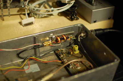
It’s the little board on the far wall of the diecast box with the SMA connector on the left and two toroids. 37-MHz RF comes in from the PTS-040 through the BNC jack in the wall. It’s multiplied up to 75 MHz on the new board and piped down to the remaining 12x multiplication and amplification stages before going to the little brick PA in the lower left (not visible).
So far, it sounds good. I was able to monitor it with my W1GHZ transverter strapped to the IC-290A in my car and using a WA5VJB cheap Yagi tossed in the back seat. I lost the signal about 5 miles away with that setup, which is really pretty decent all things considered at that frequency, etc, etc. Nominally, the frequency should be 903.054 MHz. I found it at about 903.048 MHz on the lash-up. Brian, ND3F (aka N3IQ/R) reported that he found it at 903.046 MHz with KA3EJJ’s setup. If you’re in the vicinity of FM19ne and are setup on 902/903, we’d appreciate a report. The big thing is the long-term stability. So, we’ll continue to monitor it.
Now…to get back to that 930 on my bench…
Multi-Band 4 Foot Magnetic Loop with Gamma Match

4 Foot Diameter Magnetic Loop In Operation
As my mag loop projects progress, I’m learning a lot about building them and using them. This antenna works on 17, 20, and 30 meters, with the best bandwidth on 20 meters. The bandwidth on 17 and 30 is quite small but usable. There is a 20 KHz bandwidth on 20 meters. I used a vacuum capacitor to build this particular loop for 100 watt operation. The air capacitors are good for QRP but will arc over using much power over QRP levels.

4 Foot Magnetic Loop Antenna with Gamma Match
This photo was taken before I trimmed the Gamma Match.
I didn’t know how long the Gamma Match should be, so I made it long enough to allow for trimming after the match to 50 Ohms was made.
This is the first mag loop that I made with a Gamma match. I like this match better than the usual Faraday feed loop that is featured in my previous mag loop antennas. Matching is easy and building the Gamma match is not difficult. I’m planning to build other smaller loops that will also feature the Gamma match. The smaller loops will target 10, 12, and 15 meters. Loop size determines which band its best suited too. Although it is possible to get more bands on one loop, the bandwidth is small and the tuning ‘dip’ is very sharp. I found it better to limit the number of bands in favor of wider bandwidth and antenna efficiency.
Please look up my previous posts for more details on parts and plans.

Here is a good close up of the clamp.
(Before Trimming)
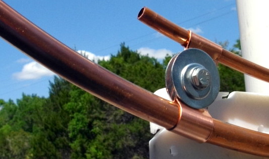
Gamma Match After Trimming. This enables a 50 Ohm Match for all three bands.

Gamma Match on the left, PL 259 in the center and, Tuning Aid Stick (PVC) pipe , on the right.
The vacuum capacitor is ‘tuned’ by twisting the PVC pipe that is attacked to it with a cotter pin.
Tuning the cap to the ‘loudest noise’ on the air will put you in the ball park for operating.
You can also use an antenna analyzer if you want to know the exact SWR, and RR of the antenna.
Tuning with a radio attached is fast and easy.

Making the clamp for the Gamma Match

Soldering The Back Plate and PL 259

Removing The Oxidation Before Soldering
The main loop is 5/8 inch, soft copper tubing.

Close Up of PL 259 to Gamma Match Joint
The center of the PL 259 had a #10 solid copper wire inserted and soldered in place.
The Gamma match is 3/8 inch soft copper tubing.
This part of the job was done with a soldering iron, the rest was done with a plumbers torch.

Handy ‘third hand’. A clamp to hold the Gamma match in place while I soldered it.
My town was going to hire a ‘Mad Scientist’ but it couldn’t afford one, so they settled for a ham radio operator instead. Me!
73 de AA1IK
Ernest Gregoire
March 2013 6 and 10
It seems that whilst 6m is still a bit low on the G7KSE listening list (Nothing to do with it still being freezing cold here and me thinking its still winter) but others have had a bit more success. The latest 6 and 1o report has been uploaded here and is available.


