Archive for the ‘radio’ Category
 W3APL/B 903-MHz beacon
 May 7th, 2013 |
  Author:
 Late last Summer, it came to my attention that the 903-MHz W3APL beacon had gone off-line. The failure was intermittent and seemed to resolve itself after power was reset. Several efforts to troubleshoot it were undertaken by myself and others, including running it at high duty into a dummy load over a period of days. I was unable to get the problem to manifest itself on my bench.
A synthesized source (Analog Devices demo board) was offered by a friend of the Club, however it did not produce the desired output (or any output at all). It’s not clear whether this was the fault of the synthesizer or the user (me). The notional plan was to replace the beacon, which consists of a 75-MHz crystal oscillator followed by 12x of multiplication and a small RF power module, with the synthesizer and a new RF power module. The project languished, as they often do in my hands. But, two weeks ago I picked up the task again and made some real headway.
Really, the failure had to be one of a couple of things: 1. Intermittent connection exacerbated by thermal cycling. 2. Oscillator “unlock” due to component aging and thermal cycling. I reasoned that as long as we could eliminate #1, the multiplier chain and amplifier should be fine. The behavior seemed to point toward #2 or perhaps a combination of #1 and #2. I came across a forlorn Programmed Test Sources PTS-040 that I had rescued from another group’s surplus heap to put in my lab. I hadn’t used it in the two years that it was in my possession, so it seemed logical to provide it to the Club on a long-term loan. The problem was that it didn’t go up to 75-MHz. So, I cooked up a little multiplier chain. My “good” HP spectrum analyzer is on-loan to a paying program so I had to make do with the FFT function on the fastest Tektronix portable scope I had in the lab.
My initial effort at the multiplier chain was to build a 2N3904 amplifier that swung way into saturation producing a signal rich in harmonics. I went straight away for the 903-MHz signal but I couldn’t get a good enough lumped-element filter to eliminate the adjacent harmonics. So, I tried for the 75-MHz injection. This demanded a buffer amplifier so I lazily reached for the MMIC drawer in and retrieved one of the plentiful MAR-8s. Plenty of gain…and, as I would find out in a moment…conditionally stable! To exercise the eloquent euphemism of Ben, N3UM, the MMIC “burst into song” at about 63 MHz.
Back to the drawing board. I knew that I had something that would work, so I redesigned the deadbug layout on an SMD protoboard (the kind with all the pads in a grid). I replaced the discrete 2N3904 and MAR-8 MMIC amps with SGA-4586Z MMICs (which are a little too nice for this service, but I have a ton of them). Viola!
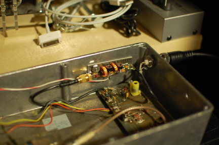
It’s the little board on the far wall of the diecast box with the SMA connector on the left and two toroids. 37-MHz RF comes in from the PTS-040 through the BNC jack in the wall. It’s multiplied up to 75 MHz on the new board and piped down to the remaining 12x multiplication and amplification stages before going to the little brick PA in the lower left (not visible).
So far, it sounds good. I was able to monitor it with my W1GHZ transverter strapped to the IC-290A in my car and using a WA5VJB cheap Yagi tossed in the back seat. I lost the signal about 5 miles away with that setup, which is really pretty decent all things considered at that frequency, etc, etc. Nominally, the frequency should be 903.054 MHz. I found it at about 903.048 MHz on the lash-up. Brian, ND3F (aka N3IQ/R) reported that he found it at 903.046 MHz with KA3EJJ’s setup. If you’re in the vicinity of FM19ne and are setup on 902/903, we’d appreciate a report. The big thing is the long-term stability. So, we’ll continue to monitor it.
Now…to get back to that 930 on my bench…
Multi-Band 4 Foot Magnetic Loop with Gamma Match

4 Foot Diameter Magnetic Loop In Operation
As my mag loop projects progress, I’m learning a lot about building them and using them. This antenna works on 17, 20, and 30 meters, with the best bandwidth on 20 meters. The bandwidth on 17 and 30 is quite small but usable. There is a 20 KHz bandwidth on 20 meters. I used a vacuum capacitor to build this particular loop for 100 watt operation. The air capacitors are good for QRP but will arc over using much power over QRP levels.

4 Foot Magnetic Loop Antenna with Gamma Match
This photo was taken before I trimmed the Gamma Match.
I didn’t know how long the Gamma Match should be, so I made it long enough to allow for trimming after the match to 50 Ohms was made.
This is the first mag loop that I made with a Gamma match. I like this match better than the usual Faraday feed loop that is featured in my previous mag loop antennas. Matching is easy and building the Gamma match is not difficult. I’m planning to build other smaller loops that will also feature the Gamma match. The smaller loops will target 10, 12, and 15 meters. Loop size determines which band its best suited too. Although it is possible to get more bands on one loop, the bandwidth is small and the tuning ‘dip’ is very sharp. I found it better to limit the number of bands in favor of wider bandwidth and antenna efficiency.
Please look up my previous posts for more details on parts and plans.

Here is a good close up of the clamp.
(Before Trimming)
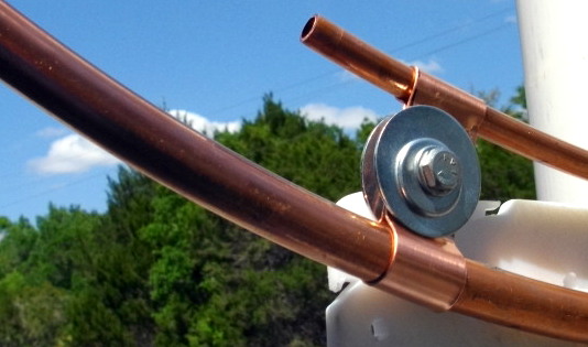
Gamma Match After Trimming. This enables a 50 Ohm Match for all three bands.

Gamma Match on the left, PL 259 in the center and, Tuning Aid Stick (PVC) pipe , on the right.
The vacuum capacitor is ‘tuned’ by twisting the PVC pipe that is attacked to it with a cotter pin.
Tuning the cap to the ‘loudest noise’ on the air will put you in the ball park for operating.
You can also use an antenna analyzer if you want to know the exact SWR, and RR of the antenna.
Tuning with a radio attached is fast and easy.

Making the clamp for the Gamma Match

Soldering The Back Plate and PL 259

Removing The Oxidation Before Soldering
The main loop is 5/8 inch, soft copper tubing.

Close Up of PL 259 to Gamma Match Joint
The center of the PL 259 had a #10 solid copper wire inserted and soldered in place.
The Gamma match is 3/8 inch soft copper tubing.
This part of the job was done with a soldering iron, the rest was done with a plumbers torch.

Handy ‘third hand’. A clamp to hold the Gamma match in place while I soldered it.
My town was going to hire a ‘Mad Scientist’ but it couldn’t afford one, so they settled for a ham radio operator instead. Me!
73 de AA1IK
Ernest Gregoire
March 2013 6 and 10
It seems that whilst 6m is still a bit low on the G7KSE listening list (Nothing to do with it still being freezing cold here and me thinking its still winter) but others have had a bit more success. The latest 6 and 1o report has been uploaded here and is available.
Ham radio for Arduino & Picaxe
The Arduino platform has struck a bit of a chord with me. It is very well supported with both hardware and software, which makes it ideal for people like me who don’t have the background or skills to get a project off the ground. There are plenty of resources around the internet that off either ready made projects (just add hardware) or Books that explain the concepts and procedures in detail. Even the books tend to be supported by websites that have the code available for download if you wish.I came across a new(?) book by Leigh Klotz Jr, WA5ZNU titled ‘Ham radio for Arduino & Picaxe’ seems to be available through the ARRL but not the RSGB at the moment.
The book is supported by a website which has forums, code and links to the various projects that are presented. The links include the almost ubiquitous Sparkfun website, which has been supplying bits and bobs to US based hobbyist’s as well as those internationally for some time. The Sparkfun site is also a good place for technical data and resources such as libraries for Eagle.
Anyway, as usual I digress. The book is currently available through the ARRL and possibly in the future through the RSGB. The contents page looks like it has a whole heap of projects that will keep us busy for a long time. If its your cup of tea then I hope you can get a copy and enjoy the projects.

New 6 and 10 reports
Martin Harrison, G3USF has provided another 6 and 10 report. Its a bit shorter than usual but we’re all blaming the conditions. It can be downloaded here
News from the shack
The end of this month see’s the end of work based madness so I’m getting a few bits and bobs sorted out.
With the demise of the trusty (read rusty…or at least corroded in the special way that aluminium does) vertical I have order a hardware kit for a Cobwebb to go outside. it may get here by the weekend. I’ve been given a rather sorry looking mast that will polish up into a rather staely looking mast once I’ve spent some time on it and a few plastic bits and pieces from Seeedstudio for some of my bits and bobs that need tidying up.
Hopefully this Saturday it won’t be freezing cold or raining, although I’m told the time I’ll be running my part of our Red Nose Day 24 hour relay it will be chucking it down, so I can assess what needs to be done to get myself back on the air on HF and get my 50Mhz yagi up and ready for the season. Looking forward to some time on the rig Excellent!
More Hexbeam
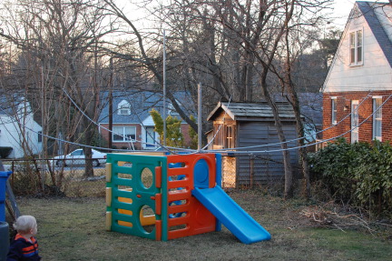
“What have you done to my play set?” This gym made a convenient place to string wires, etc. Two poles in the photo form part of the EWE RX antenna here at K8GU that was hastily erected before the NA Sprint CW. One of the poles is ty-wrapped to the play set. Doing my best to keep it klassy and impress the neighbors.
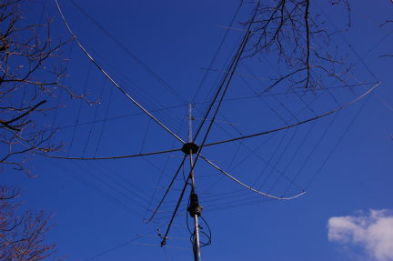
And, we’re up in the air! The M2 9M2SSB is a little bit out of alignment due to the hex getting tangled in one of the antennas that it was due to replace. I have already realigned that. So far, the antenna seems to have useful front-to-back. Gain is hard to tell since I took down all of the antennas it was to replace. But, it does seem to work. I’m suffering from high SWR (above 3) on both 21 and 50 MHz. G3TXQ warns of interaction between 18 MHz and 50 MHz. Do not yet know the cause, but I’m looking into it.
Although the antenna is relatively easy to handle, I don’t plan to make a habit of taking it down for work. Speaking of taking down, the 40m dipole whose center insulator is just visible behind the reflector of the 2-meter beam will be replaced by an as-of-yet-secret antenna.